4 Commissioning
4.1 Power supply
c
onnection
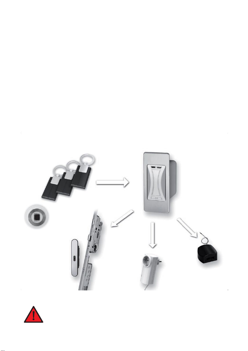
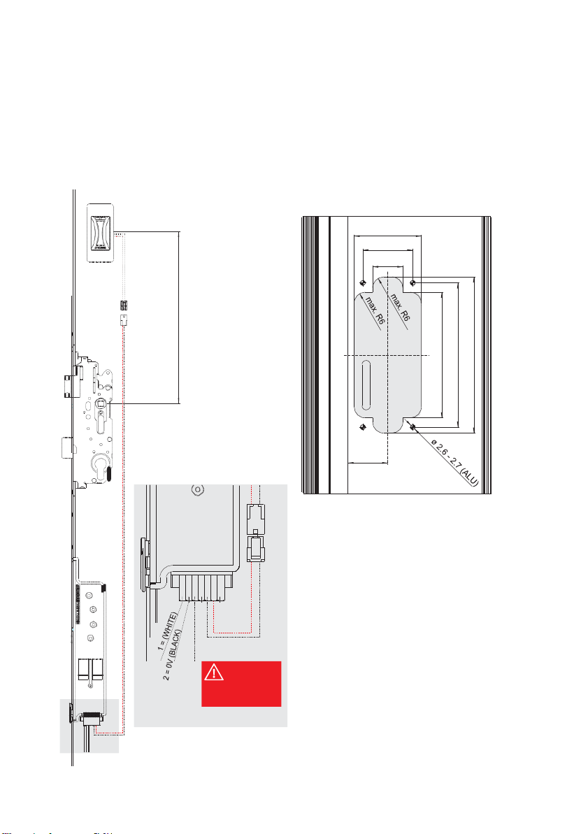
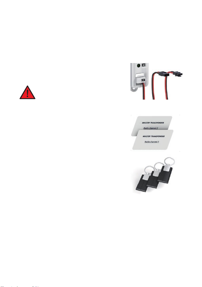
The
radio transponder reader
requires
12 V
DC
(direct current)
oper
a
ting
voltage, collected directly from the motor lock’s drive unit.
For
more on
this, refer
also
to chapter3.1, page
5.
Terminal
5
=
–pole, terminal 6
= +
pole.
Please
no
t
e!
Pleaseobserve the correct
polarity
(+/-)
to the
power
sour
ce!
4.2 Delivery
s
t
a
tus
Both
the
master transponders and
the
user transponders enclosed
in the set
have already been
tuned in to the radio transponder
reader
in the
f
act
or
y
.
In addition, the
master transponders have been labelled
with “radio chan-
nel 1” and “radio
channel
2” at the factory.
The master cards are
only used
for tuning in and deleting
user transponders.
These
cannot
be used
to open
motor locks.
All three user
transponders
have been tuned in to “radio channel 1”
a
t
the factory.
These
user
transponders
can as a result only be used to open
motor-lock doors.
Upon connecting up the 12 V DC operating voltage, these user
tr
ans-
ponders
that have already been tuned in, can be used immediately
t
o
create
a radiotelegram.
In order to open the motor-lock door with the radio transponder reader,
it
is
imperative
to note chapter5.2, page
9.
4.3 Two
transmitting
channels for
different
device
s/door
s
The
radio
transponder reader iscapable
of transmitting opening
impulses
ontwo different
channels. This results
in
the
advantage
of being
able
to control two different
devices
with one radio transponder reader.
Channel 1
For
the
multitronic/autotronic
main door
Channel 2
For
another
multitronic/autotronic
door or, in conjunction with the FUHR radio receiver
NZ80023/NZ80088,
for amotorised
garage
door drive unit or an
electrical
yardgate.
A
user
transponder canalways only be
tuned into
one
of the two
channels;
never
for both
channels
simultaneously. If
you would like to control two different
doors
with one transponder reader, you must use two different user
transponders.