FujiClean CE6KG User manual

Contractor Installation Manual
Commercial Systems
Including
H-20 Installation
CE and CEN Models
(except Model CE6KG)
Rev. 11-2 -20
Fuji Clean USA ● 41-2 Greenwoo Roa ● Brunswick Maine 04011 ● Tel: 207-406-2927 ● Fax: 888-789-1977 ● www.fujicleanusa.com
Warranty Activation. To activate system warranty, Fuji Clean USA must receive Warranty Activation Card!

Equipment Supplied to Contractor
Signalmaster Float
Switch
(Affix to pumpback line in center
chamber with 3-1/2” tether)
FujiMAC UL Approved
Air Blower(s) (Blower size and
quantity according to model. Blower
barb hole for smaller models
Alarm / Control Panel
(NEMA X Rated)
Thank you for choosing to install a Fuji Clean treatment system. We care that the system is
installed properly and thoughtfully. Fuji Clean USA or your qualified distributor will train and
certify you for proper installation. Please be aware that not every item below comes with every
model. Component needs vary according to model. Please call Fuji Clean USA with questions.
NSF Dataplates (2)
(Smaller models only)
Installation Manual, User’s Manual, Warranty Card
Fuji Clean Processor Tank
Air Vent Hole and Plug
(Tighten clockwise. Plugs the vent hole if
venting through building. Note: some
models have two vent holes.)
Risers & Covers (height may
vary – check with local distributor)
Blower adaptor Fitting
with Barb (For larger models.
Not provided/necessary with “M”
Alarm Panel)
1/8” (ID) Vinyl Micro-Tubing for Air
Pressure Sensing Alarm. (Not provided/necessary
with “M” Alarm Panel)
Eccentric Inlet/Outlet 5x Bushing (2) (Larger models
only)
2
Airline to Tank Adapter
(For CE1 and CEN10.
Unglued. Glue during installation.)

Equipment Supplied by Contractor
Risers an Access covers per Site & Regulatory Requirements
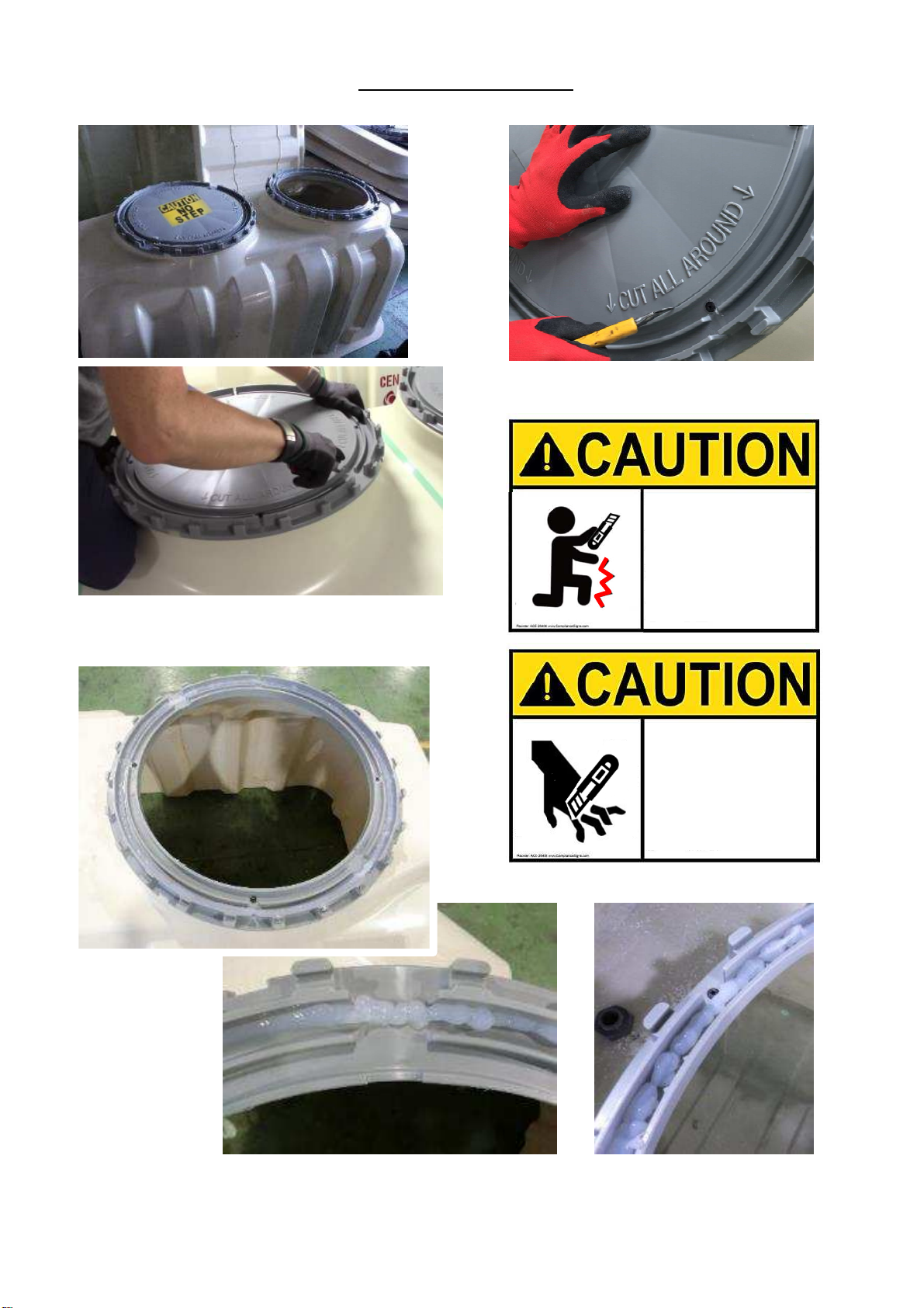
Risers in 6” or 12” height increments and access covers are available from your distributor. If not already installed,
please refer to installation instructions in this Manual. Maximum riser height is 2 inches for No traffic load and H-
20, HS-20 with Support Columns. For H-20, HS-20 with No Support Columns, acceptable riser height is 12 inches to
set the depth 2 inches between ground level and adapter ring.
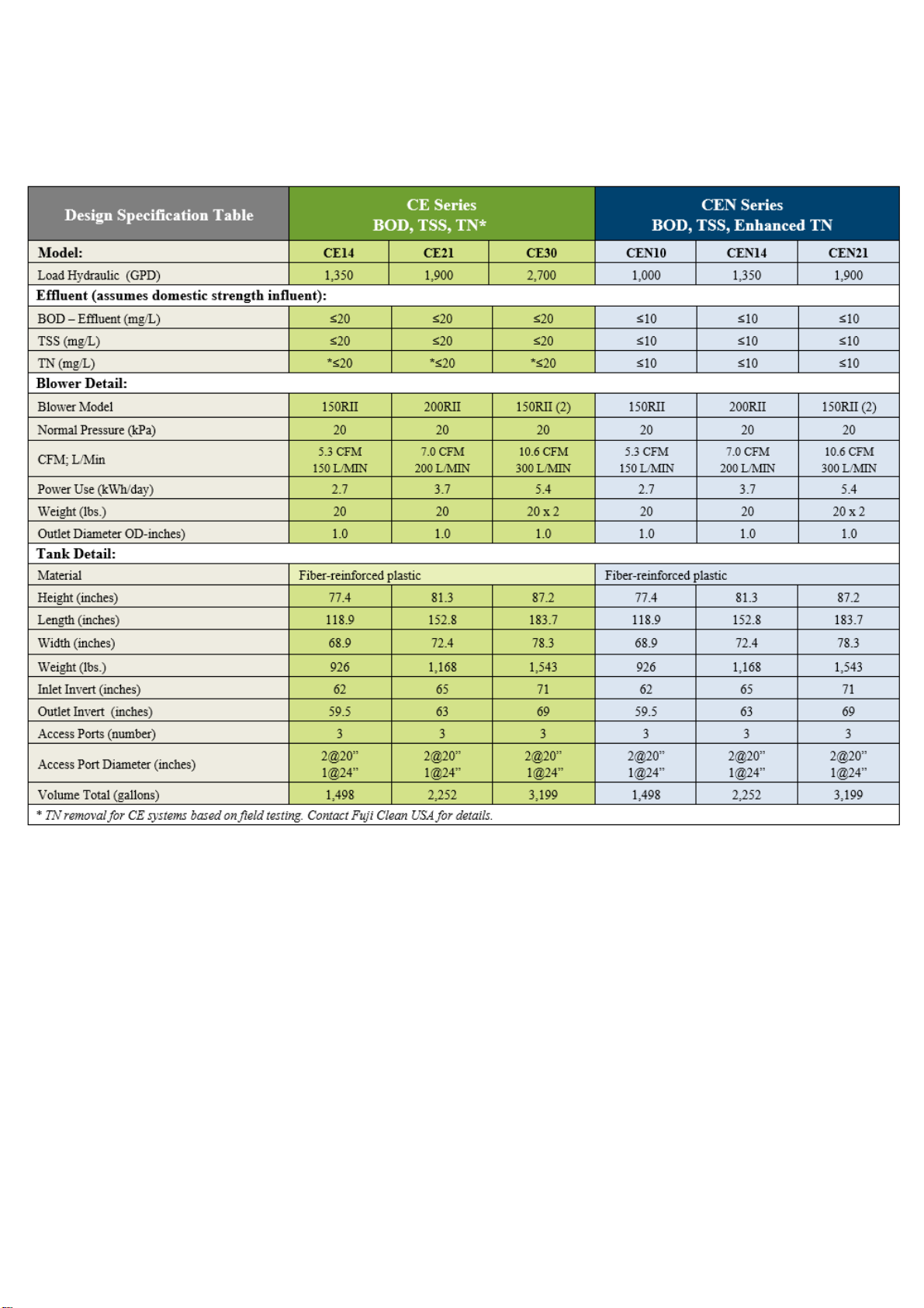
All Commercial Mo els: Two (2) 20-inch dia. Risers plus One (1) 2 -inch dia. Riser.
Insulation for Col Climate Installations
To maintain optimal treatment conditions, Fuji Clean recommends insulated risers and access covers as well as
foam board or insulating material (min. R-Value 8) over the upper half of the treatment tank. In H-20, HS-20 with
No Support Columns installation, insulate at depth of 2 inches between ground level and adapter ring.
Septic Tank an /or Pump Station.
For commercial system, structure use with high influent load cases, install a septic tank if necessary. Fuji Clean
systems are designed to accept straight wastewater. However, some treatment train designs call for pretreatment,
settling and/or trash tanks.
Fresh Water
Systems must be filled with fresh water to Low Water Level before backfill. Please refer to Approx. gallons required
per model is “Volume Total” on page 7.
Piping / Con uit
•Smaller models have inlet/outlet adapters for sched. 0 ” pipe. Models CE1 , CE21, CE30, CEN1 , CEN21
fittings are for 5” sched. 0 pipe and come with a 5”: ” eccentric adaptors, to accommodate sched. 0 ” pipe.
•¾” or 1” PVC conduit for air line. Flexible irrigation line, 100 PSI Max, (or equivalent) is also acceptable.
•Electrical conduit for float switch line (direct burial line is also acceptable if allowed by code).
Electrical
•Please use licensed electrician and adhere to applicable national/local electrical code(s).
•Two (2) standard 115V, 15A circuits for control/alarm panel connection.
•Float Switch Wire: #18 AWG, comes with standard 30’ length. (Longer lengths are available on request).
•Float Switch: May come pre-installed in treatment system. For electrical hookup, please refer to SJE Rhombus
installation instructions.
•Miscellaneous fittings and connectors to assure watertight connections.
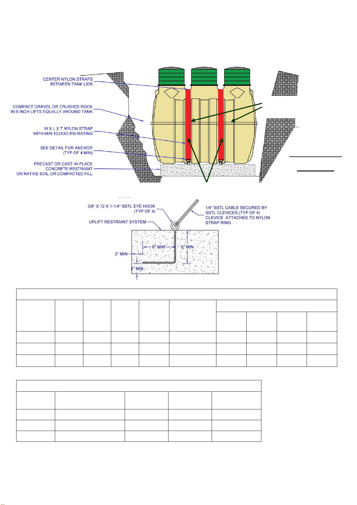
Anti-Float Devices, if necessary
•Please refer to high water, uplift restraint recommendations in this Manual.
Materials for Air Blower / Controller Installation
•Concrete base (or equivalent) on which to set air blower.
•Protective cover for air blower (recommended) vented and able to achieve free air flow in all conditions.
•Materials or location on which to mount control panel and protect from elements.
Crushe Stone, Fill, Loam etc.
•H-20 and HS-20 load needs concrete base.
•Fuji Clean USA is not responsible for design, installation or materials associated with leach field or treated
wastewater disposal area.
Please note: Proper installation permitting is the responsibility of the installing contractor.
Contractor Installation Manual – Commercial Systems
3

Installation Overview
Fuji Clean USA
Treatment System
Please Note: Fuji Clean systems are designed to accept straight
wastewater. However, some treatment train designs call for
pretreatment, settling and/or trash tanks.
Sched. 0 PVC inlet and outlet pipe
Air line to Treatment System
Pump Station
(if site conditions
dictate)
Septic Tank
(Optional)
MAC “R” Air
Blower
Adaptor and fittings (supplied by Fuji Clean
USA) for connection between treatment
system and FujiMAC Series “RII” Air blower.
System Controller/Alarm
including options for
telecommunication, simplex
and duplex pump control,
flow monitoring and data
logging.
FujiMAC “RII”
Commercial Series
linear diaphragm air
blower, typically 150-
300 liters/min for
commercial
applications.
Systems may be clustered
in parallel configuration for
treatment of larger flows.
Fuji Clean commercial
treatment systems are
delivered plug & play ready
with no onsite assembly
required.
Multiple system configurations may be
controlled independently (shown) or by
one customized controller.
Air pressure line is not supplied
with systems that use an “M”
panel as current sensors are
used instead.

Treatment Process Overview
Fuji Clean’s “contact filtration” treatment is a simple, well engineered process that consists of a controlled, circuitous
flow train through anaerobic and aerobic chambers and in direct contact with assorted proprietary fixed film medias
on which biological digestion of organic matter occurs. Media is also designed and positioned to provide mechanical
filtration of process wastewater.
The system includes two air lift pumps (see diagram below). The Recirculating Airlift Pump returns process water and
sludge from the aerobic zone to the sedimentation chamber, recirculating 2- times inflow per day for CE models and
-6 times inflow for CEN (enhanced denitrification) models. The Effluent Airlift Pump is designed to help equalize flow
and discharge treated effluent.
5
Outlet
Air
Slu ge Transfer
(Recirculating air lift pumpback)
Chamber 3B. Disinfection Chamber
(final zone before discharge – option for chlorination tablet disinfection)
Chamber 1.
Se imentation Chamber
(separates solids and greases)
Chamber 3. Aerobic Contact
Filtration Chamber
(both board and cylindrical hollow
mesh media) oxygen rich zone for
aerobic microbe digestion activity,
solids filtration and nitrification of
ammoniac nitrogens to nitrates
Powere by the FujiMAC “Rll” Series
Blowers State-of-the-art linear
diaphragm air blowers manufactured
by Fuji Clean Co sized to provide
about 2.8 cubic feet per minute to
most Commercial systems.
Chamber 2.
Anaerobic Filtration Chamber
(spherical-skeleton filter media)
organic matter decomposition by
micro-organisms, suspended
solids are captured and nitrates
are denitrified
Chamber 3A. Clarification Chamber (settling zone)
Two Air Lift Pumps. One Recirculating Air
Lift pump sending process water and solids
back to Chamber 1, and one Effluent Air Lift
Pump for measured discharge of treated
effluent. (See airlift pump info below).
Airlift Pumps. This generic illustration
shows the mechanics of the “airlift
pumps” used in this system, which are
simple pipe conduits through which
pressurized air (from blower) is
introduced at the bottom and by fluid
pressure, water is carried up the pipe
by ascending bubbles.
Flow Equalization
When water level
exceeds LWL, treated
water is discharged
through Chamber 3B
via the Effluent Air Lift
pump. If water level
exceeds HWL, then
treated water is also
discharged through an
overflow effluent weir.
Overflow Effluent Weir
During treatment,
water level fluctuates
between high and
low water levels
Inlet

6
System Components an Specifications - Summary
* TN data was obtained during CE testing, but not to NSF2 5 testing protocol. CEN testing was to NSF2 5 protocol.
** Please consult with distributor or Fuji Clean USA for commercial models designed to treat hydraulic flows above
those listed in this table.
*** Please consult with distributor or Fuji Clean USA for system specification and sizing in cases where influent
biologic strength is greater than domestic strength.
Structural drawings of all Commercial models are available in both .dwg and pdf formats online
at www.fujicleanusa.com

7
Use sharp bla e to remove inner plastic ring.
*Safety consi erations!
Squeeze silicone
or approve
waterproof
sealant into base
frame groove.
20-inch ia.
(1st an 2n Openings)
24-inch ia.
(3r Opening)
Riser Installation-1
INJURE YOUR
LEGS WHEN
YOUR HAND
SLIPPED
CUT YOUR
FINGERS WHEN
YOUR HAND
SLIPPED WITHOUT
GLOVES
Sli e several times on the cutting groove
is easier.

8
Polylok Risers. Align mol e “frame block” with riser screw hole. Insert screw an screw tight.
Recommen e screw length: 1 ½” (If it's too long, it won't fit in "frame block“.)
Riser Installation-2
Tuf-Tite Risers. Align riser screw holes with mol e “frame block”
an screw tight.
Recommen e screw length: 1 ½”
(If it's too long, it won't fit in "frame block“.)
frame
block
Apply silicone to
the screw hea
to prevent water
penetration.
MAKE SURE TO INSTALL RISER ON PP-ADAPTER RING.

No-traffic Area Installation Procedure
Step 1: Prepare excavation to be at least 1 to 2 feet
larger than Fuji Clean system imensions as liste in the
Design Specification Table on page 7 of this Manual.
Important Note: Total height from tank top to gra e
shoul not excee 24”.
Step 2. Prepare 4”- 6” be of stone (1/8”), compact
san , poure or precast concrete level to within 1/8”
per 2 feet. (10mm per 2 meter or 1/200).
Unloa ing Instructions:
Upon delivery, inspect Fuji clean tank, both outside and inside for possible damage incurred
during transport. If you find damage, or have a question, please contact your distributor
immediately.
9
Compact stone or san
Use ALL 4-point lifting lugs
Step 3: Carefully lower an set tank.
Level to within 1/8” per 2 feet.
(10mm per 2 meter or 1/200).

10
Step 4: If any part of the tank is below the estimate seasonal high water table, then engineer shall
provi e buoyancy calculations to assure a equate tank uplift restraint.
CONCRETE UPLIFT RESTRAINT REQ’D FOR FUJI CLEAM CE,CEN SERIES MODELS BASED ON GROSS TANK DIMENSIONS
MODEL HEIGHT
(FT)
WIDTH
(FT)
LENGTH
(FT)
VOLUME
(FT3)
DISOLACEMENT
(LBS)
CONCRETE VOLUME (CY)
@3050
LB/CY
WITH
10% FS
WITH
25% FS
WITH
50% FS
CE1 /CEN10 6. 167 5.750 9.9167 366 22,839 7. 9 8.2 9.36 11.23
CE21/CEN1 6.8750 6.000 12.7292 526 32,823 10.76 11.8 13. 5 16.1
CE30/CEN21 7.3333 6. 792 16.250 773 8,236 15.82 17. 0 19.77 23.72
SLAB DIMENSIONS FOR 50% FACTOR OF SAFETY
MODEL CONCRETE VOLUME (CY)
WITH 50% FS
SLAB WIDTH
(FT)
SLAB LENGTH
(FT)
SLAB THICKNESS
(FT)
CE1 /CEN10 11.23 6.00 10.00 5.055
CE21/CEN1 16.1 6.00 13.00 5.588
CE30/CEN21 23.72 7.00 17.00 5.382
Tie own straps
Do NOT use Lifting Lugs
for uplift restraint.
TIE-DOWN
STRAPS

11
Step 6 continue .: Install inlet an outlet pipes using primer an cement. For larger systems with 5”
inlet an outlets, you may use 5”: 4” eccentric re ucer a apters inclu e with system. Install with
thin e ge own. Apply primer an cement to 4” PVC pipe sections to inlet an outlet.
Step 6: Backfill about 3/4 way up tank in layere , compacte 6” lifts using san , stone ust,
peastone or equivalent material that form-fits into tank corrugations. Keep backfill material
amp to assure compact backfill an re uce settling risk.
Please note: To assure tank water tightness, check in 24 hours to be sure that the water level
has not roppe . Contact your istributor or Fuji Clean USA if water level has roppe .
Step 5: After rechecking that tank is level to 1/8” per 2 feet (10mm
per 2 meter or 1/200), (fore an aft as well as si e to si e), fill tank
with fresh water to the low water line in ALL 3 chambers.
Note: Start with center chamber an alternate chambers while filling
for evenly balance fill.

Step 7: Using supplie a aptors an fittings, attach air pipe fitting to tank an connect to ¾” or 1”
con uit in prepare trench (min. 6” eep) to location of air blower. Please note: ¾” or 1” flexible
irrigation line, 100 PSI Max, (or equivalent) may also be use for the air line.
12
3/ ” PVC air line can insert directly
into commercial tank models, CE21
and larger and CEN1 and larger.
Step 7 continue : Set riser on the tank.
Maximum riser height is 24-inches.
CE14/CEN10
FujiMAC 150RII
CE21/CEN14
FujiMAC 200RII
CE30/CEN21
FujiMAC 150RII (2)
Blower Outlet Pipe 3/ ”
Air Intake at Tank φ13 ※φ20 ※φ20 ※
Blower to Tank Distance /
Airline Conduit Dia.
<33 Feet /
3/ ”
<100 Feet/
1”
< 33 Feet
3/ ”
<100 Feet
1”
<33 Feet
1”
<100 Feet
1”
For connection air line to tank, use sealant
meeting ASTM C990-96 standard to prevent
septic gas transmission into control panel.
(Note: A aptors to tank are not necessary for air line to tank connection for Fuji Clean mo els, CE21 an
larger an CEN14 an larger. Use 3/4” con uit). A aptors to tank are necessary for air line to tank
connection for CE14 an CEN10.
LOCATE BLOWER WITHIN 33-FT OR 100-FT OF TREATMENT TANK (FOLLOW CONDUIT ON TABLE BELOW)
AND WITH NO MORE THAN FIVE (5) ELBOWS (FOLLOW BLOWER FOUNDATION DRAWING BELOW). If site
con itions prevent this, please contact your istributor or Fuji Clean USA for technical assistance.
※Japanese pipe dia.
Excluding
in “5 Elbows”

13
Step 8: Locating an Installing Blower/Control Panel.
Air Blower shall be:
in as close proximity to control panel as possible
on a soli (e.g. concrete) pa to minimize vibrations
in a location above water level
away from grease exhaust fans
away from be room win ows an other locations
where operational soun s (although minimal) may be
a nuisance
in a location that allows unencumbere access for
inspection an maintenance activity
with proper electrical groun ing
with wiring an electrical connections ma e by a
license electrician
with no objects on top of electrical cor
in a well-ventilate space out of irect sunlight an
protecte from elements
Alarm Panel shall be:
in a well ventilate area as ry an protecte from
elements as much as possible
in as close of proximity to FujiMAC air blower as
possible
wire by qualifie electrician
in a location that allows unencumbere access for
inspection an maintenance activity
Be sure to vent blower protection cover to
allow free air raw even in eep snow pack.
Note: For Fuji Clean mo els CE30 an CEN21 (which both
require two blowers), the 1/8” (ID) Vinyl Micro-Tubing for
Air Pressure Sensing Alarm is replace with current sensing
switches, supplie with the “M” panel.
Please provi e
service contact
information on
the control panel.
¾”
¾”
1”

1
Step 9: For col climate installations, please install insulate risers an access covers an cover
upper half of treatment unit with min. R-8 value insulating material (i.e. foam boar ).
Step 10: Float switch electrical cor connect through a male a aptor (caulke watertight
to prevent septic gas leakage) or watertight fitting. An interior connection to irect burial
cable is also an acceptable option.
For connection of float switch cord to alarm panel, drill
hole in riser and use male fitting and electrical conduit.
Plug fitting with sealant standard that meets ASTM C990-
96 to assure water-tight seal and to prevent septic gas
transmission into control panel.
Caulked around cable
in the pipe

15
Step 11: In most cases, the Fuji Clean treatment system will vent through the buil ing’s septic influent
line an buil ing plumbing. In cases where there is an influent pump, or in severe own raft
locations, a separate vent shoul be consi ere . If you o choose to install a vent, be sure that the
vent slopes towar the tank so that any moisture accumulation rips back own towar the tank.
Step 12: During final lan scaping, see ing
etc., be sure to pitch final gra e away from
covers to sweep surface water away from
treatment tank.
Step 13: Fill out Warranty Activation Car (receive with this Installation Manual) an return to
Fuji Clean USA to activate system Warranty. If this car cannot be foun , please contact Fuji
Clean USA for voice or online Warranty activation. 207-406-2927.
3” port for optional air vent line. If not use ,
install plug in port by turning clockwise to tighten.
(Note: 2 ports in CE21, 30, CEN14 an 21).
If optional air vent line is installe ,
slope con uit towar tank to
prevent moisture accumulation
ONE unit <16 feet >16 feet
Commercial 3” (φ75) ” (φ100)
Local regulations may specify require vent pipe
iameter
Keep horizontal vent pipe as short as possible.
Vertical pipe length shoul be 2 times longer than
horizontal
Installation of a positive flow ventilation fan
facilitates better ventilation
Greater temperature ifferential between tank an
outsi e air facilitates more effective ventilation
One vent line is able to connect system clusters of
2 to 4 units with 4" iameter pipe.
Joining point of tank an vent line within 16feet.
In case of over 5 units, use two (2) vent lines.
Vent pipe iameter

16
Step 1: Excavation
Prepare excavation to be Fuji Clean
treatment system imensions as
liste on page 7 an concrete slab
imensions on page 22.
1
2
Step 2: Compact stone base
Installation Procedure for H-20, HS-20
Unloa ing Instructions:
Upon delivery, inspect Fuji Clean tank, both outside and inside for possible damage incurred during
transport. If you find damage, or have a question, please contact your distributor immediately.
Require Precon itions for this Installation Technique
Seasonal high groundwater depth must be less than 3’3” (1000mm).
Total height from ground level to adapter ring should be 2 inches.
Bearing power of soil must be 8.7 PSI or greater.
Important Note: Total height from groun level to a apter ring shoul be 24 inches.
Make sure excavation of slope shoul be 2:1 as a zone of influence. If slope will be gentle ue
to weak foun ation, install lan sli e protection wall.

17
Step 4: Set tank
Step 5: Fill tank with fresh water to
Low water level mark in all 3
chambers.
Note: Start with center chamber an
alternate chambers while filling for
evenly balance fill.
Water
To assure tank water tightness, check in 24 hours to be sure that the water level has not roppe .
Contact your istributor or Fuji Clean USA if water level has roppe .
Use 4-point lifting lugs. Carefully
lower an set tank.
Check that tank is level to 1/8” per 2
feet, (10mm per 2 meter or 1/200),
fore an aft as well as si e to si e.
Step 3: Set pre-cast concrete or
pour concrete base.
H-20 an HS-20 loa nee s
concrete base.
Bearing power of soil shoul be
8.7PSI or more.
Pre-cast concrete base
Check the concrete is level to 1/8” per 2 feet
(10mm per 2 meter or 1/200),
(fore an aft as well as si e to si e).

18
Step 6 continue : Install inlet an outlet pipes using primer an cement. For larger systems with 5”
inlet an outlets, you may use 5”: 4” eccentric re ucer a apters inclu e with system. Install with
thin e ge own. Apply primer an cement to 4” PVC pipe sections to inlet an outlet.
Step 6: Backfill about 3/4 way up tank in layere , compacte 6” lifts using san , stone ust, pea stone
or equivalent material that form-fits into tank corrugations. Keep backfill material amp to assure
compact backfill.
Water

19
Step 7: Using supplie a aptors
an fittings, attach air pipe fitting
to tank an connect to ¾” or 1”
con uit in prepare trench (min. 6”
eep) to location of air blower.
Please note: ¾” or 1” flexible
irrigation line, 100 PSI Max, (or
equivalent) may also be use for
the air line.
For connection air line to tank, use
sealant meeting ASTM C990-96
standard to prevent septic gas
transmission into control panel.
(Note: A aptors to tank are not necessary for air line to tank
connection for Fuji Clean mo els, CE21 an larger an CEN14
an larger. Use 3/4” con uit). A aptors to tank are necessary
for air line to tank connection for CE14 an CEN10.
LOCATE BLOWER WITHIN 33-FT OR 100-FT OF TREATMENT
TANK (FOLLOW CONDUIT ON TABLE BELOW) AND WITH NO
MORE THAN FIVE (5) ELBOWS. Refer to elbow counting page 13.
If site con itions prevent this, please contact your istributor
or Fuji Clean USA for technical assistance.
3/ ” PVC air line can insert directly
into commercial tank models, CE21
and larger and CEN1 and larger.
CE14/CEN10
FujiMAC 150RII
CE21/CEN14
FujiMAC 200RII
CE30/CEN21
FujiMAC 150RII (2)
Blower Outlet Pipe 3/ ”
Air Intake at Tank φ13 ※φ20 ※φ20 ※
Blower to Tank Distance /
Airline Conduit Dia.
<33 Feet /
3/ ”
<100 Feet/
1”
< 33 Feet
3/ ”
<100 Feet
1”
<33 Feet
1”
<100 Feet
1”
Step 7 continue : Set riser on the tank.
Step 8: Locating an Installing Blower/Control Panel. Please refer the etails page 14.
Step 9: Float switch electrical cor connect through a male a aptor (caulke watertight to
prevent septic gas leakage) or watertight fitting. An interior connection to irect burial cable is
also an acceptable option.
※Japanese pipe dia.

20
Step 10: In nearly all cases, the Fuji Clean treatment system will vent properly through the buil ing’s
septic influent line. In cases where there is an influent pump, or in severe own raft locations, a
separate vent shoul be consi ere . If you o choose to install a vent, be sure that the vent slopes
towar the tank so that any moisture accumulation rips back own towar the tank.
3” port for optional air vent line. If not use ,
install plug in port by turning clockwise to tighten.
(Note: 2 ports in CE21, 30, CEN14 an 21).
If optional air vent line is installe ,
slope con uit towar tank to
prevent moisture accumulation
Local regulations may specify require vent pipe
iameter.
Keep horizontal vent pipe as short as possible.
Vertical pipe length shoul be 2 times longer than
horizontal.
Installation of a positive flow ventilation fan
facilitates better ventilation.
Greater temperature ifferential between tank an
outsi e air facilitates more effective ventilation.
Step 11: Backfill up to slab
base. Compact tightly. Keep
backfill material amp to
assure compact backfill an
re uce settling risk.
Note: Bearing power of soil
un er slab shoul be 4.4PSI
or more.
Water
ONE unit <16 feet >16 feet
Commercial 3” (φ75) ” (φ100)
Vent pipe iameter
One vent line is able to connect system clusters of
2 to 4 units with 4" iameter pipe.
Joining point of tank an vent line within 16feet.
In case of over 5 units, use two (2) vent lines.
Table of contents
Other FujiClean Water System manuals
Popular Water System manuals by other brands

Armstrong
Armstrong AGE4 Installation and operating instructions

Vortex
Vortex Setur-M user manual

Rinnai
Rinnai REU-VR3237WG Service manual

Everpure
Everpure Coldrink 1-MC2 System EC210 Specification sheet

ModvlvS
ModvlvS Kascata manual

CRANE PUMPS & SYSTEMS
CRANE PUMPS & SYSTEMS Barnes PGPT Series user guide

GEP
GEP Breaky 1 installation manual

CitrinSolar
CitrinSolar CS-ZV Manual for the specialised craftsman

Ecosoft
Ecosoft MO 5-36 Installation and operation manual

Atlas Filtri
Atlas Filtri DOSAPLUS 2 quick start guide

Technische Alternative
Technische Alternative FRISTAR3 operating manual

Halsey Taylor
Halsey Taylor HTVZDBL*1C series owner's manual