14
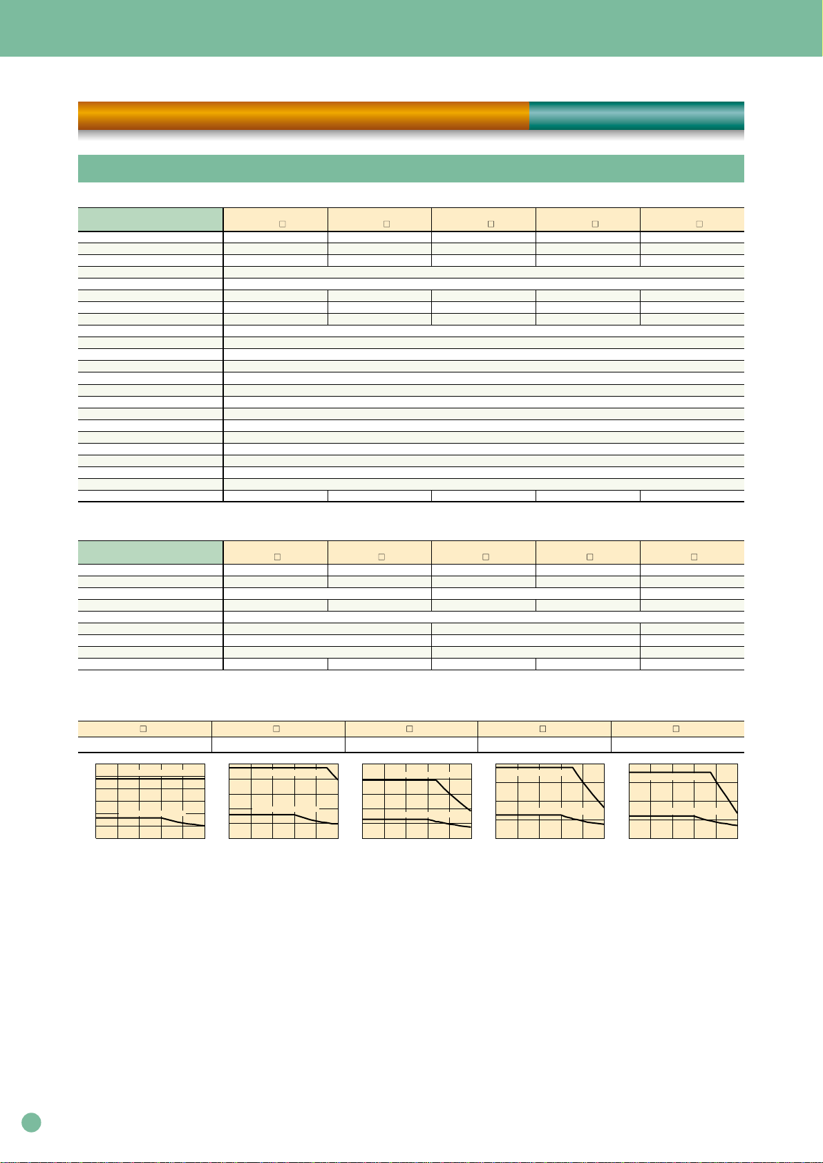
Basic specifications
Outer frame number
MassMain power
supply
Control power
supply
Control system
Feedback
Sequence input
(CONT1 to 5)
Sequence output
(OUT1 to 4)
Encoder signal
dividing output
Monitor output
Max. command pulse frequency
Input pulse signal form
Input pulse type
Command pulse
correction
Position control input
Speed control range
Acceleration/deceleration time setting
External speed command input
Internal speed setting
Speed control input
External torque command input
Torque control input
Regenerative braking
Additional functions
Protection
Installation place
Temperature/humidity
Vibration/shock resistance
Standards
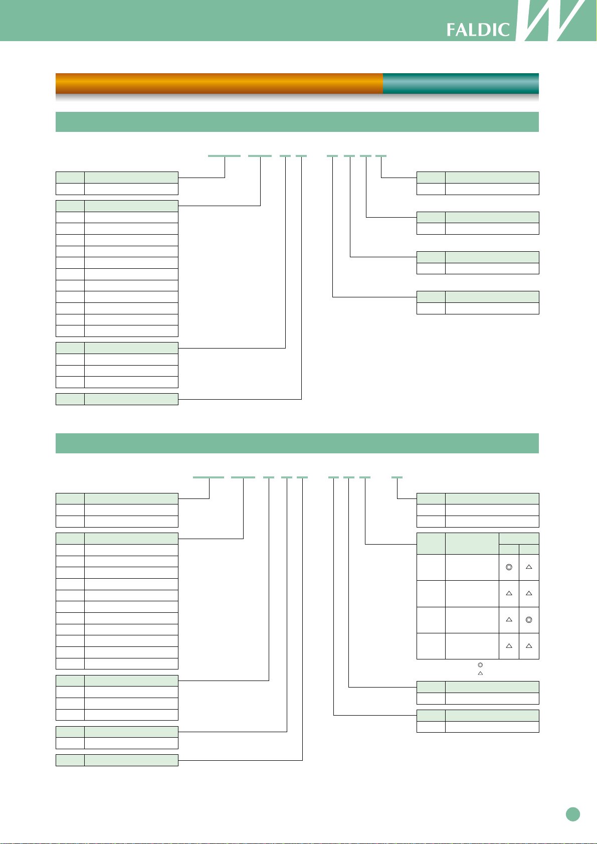
Type
RYC
Power supply
Functions, input/output signals
Position control
Working
conditions
3000 [r/min]
0.05 kW
500
Frame 1
1.0 [kg]
Single-phase
AC200 to 230 [V] -15 [%] to +10 [%] (-10 [%] to +10 [%] at Single-phase)
50/60 [Hz]
Single-phase
AC200 to 230 [V] -15 [%] to +10 [%]
50/60 [Hz]
IGBT PWM sinusoidal PWM drive
17-bit incremental encoder
(1) Servo ON, (2) +over-travel, (3) -over-travel, (4) emergency stop, (5) P-action, (6) free run command, (7) anti-resonant frequency selection 1,
(8) anti-resonant frequency selection 2, (9) control mode switching, (10) external regenerative resistor overheat, (11) alarm reset
These functions can be assigned to sequence inputs CONT1 to CONT5 and used. (*1)
(1) Servo ready, (2) positioning complete, (3) servo alarm detection a-contact, (4) servo alarm detection b-contact, (5) dynamic braking control,
(6) over-travel detection, (7) emergency stop detection, (8) deviation zero, (9) speed zero, (10) current limit detection, (11) brake timing
These functions can be assigned to sequence outputs OUT1 to OUT4 and used.
Pulse output setting 16 to 32768 (pulses/rev)
(1) Line driver output A-phase, B-phase, and Z-phase, (2) open collector output Z-phase
Analog voltage output for signal measurement (alternating, pulsating) ×2
(1) Speed command, (2) speed return, (3) torque command, (4) positional deviation, (5) positional deviation expansion, (6) pulse command frequency
These functions can be assigned to monitor outputs MON1 and MON2 and used, and the output voltage scale and offset can be set by setting parameters.
Pulse frequency (max.) command input 1 [MHz] (differential), 200 [kHz] (open collector), dividing output 500 [kHz] (differential)
Compatible with two systems: (1) RS-422 line driver signals and (2) open collector signals
Selectable from (1) command pulse/command sign, (2) forward operation/reverse operation pulse, and (3) two 90°phase-different signals
(1) Command pulse correction αselection 1, (2) command pulse correction αselection 2, (3) deviation clear, (4) command pulse disabled
These functions can be assigned to sequence inputs CONT1 to CONT5 and used. (*1)
1:5000
0 to 10 [s]/2000 [r/min], acceleration and deceleration times can be set separately, two acceleration times and deceleration times can be set, S-curve acceleration/deceleration is possible.
Speed control by analog voltage commands, ±10 V input, the voltage-speed scale and offset can be set by setting parameters.
Three speeds can be set by setting internal parameters.
(1) Multi-speed selection 1, (2) multi-speed selection 2, (3) forward operation, (4) reverse operation, (5) acceleration/deceleration time selection
These functions can be assigned to sequence inputs CONT1 to CONT5 and used. (*1)
Speed control by analog voltage commands, ±10 V input, the voltage-torque scale and offset can be set by setting parameters.
(1) Forward operation and (2) reverse operation can be assigned to sequence inputs CONT1 to CONT5 and used. (*1)
Regenerative braking to DC intermediate circuit, the regenerative resistor can be externally installed.
Zero clamp function, vibration suppressing control, notch filter, easy tuning, brake timing output, etc.
Overcurrent (OC1, OC2), overspeed (OS), overvoltage (Hv), encoder error (Et), control power error (Ct), memory error (dE), regenerative transistor overheat (rH2),
encoder communication error (EC), CONT duplication (Cnt), overload (OL), insufficient voltage (LV), regenerative resistor overheat (rH1), excessive deviation (OF), amplifier overheat (AH)
For indoor use at max. altitude of 1,000 m or below. The installation place shall be free from dust, corrosive gas, or direct sunlight. To meet European standards: Pollution degree = 2, overvoltage category =
-10 [°C] to 55 [°C]/10 to 90 [%RH] (without condensation)
4.9 [m/s2]/19.6 [m/s2]
Conforming to UL/cUL (UL508c) and CE Mark (low voltage directive EN50178)
Applicable motor rated speed
Applicable motor output
D3-VVT2
C3-VVT2
B3-VVT2
0.1 kW
101 0.2 kW
201 0.4 kW
401 0.75 kW
751
Frame 2
1.5 [kg]
Single-phase, 3-phase
Frame 2 Frame 2
1.5 [kg]
Single-phase,
3-phase 3-phase
Frame 3
2.5 [kg]
3-phase
Frame 3
2.5 [kg]
2000 [r/min]
0.5 kW
501
0.75 kW
751
1 kW
102
1.5 kW
152
2 kW
202
1500 [r/min]
0.5 kW
501
0.85 kW
851
1.3 kW
132
Interface specifications
Terminal name Code Specification
Pulse train input
Frequency dividing output
Analog input
Power input for sequence signals
Sequence input signal
Sequence output signal
Monitor output 1, monitor output 2
CA, *CA
CB, *CB
PPI
FFA, *FFA
FFB, *FFB
FFZ, *FFZ
FZ, M5
Vref
P24
M24
CONT1 to CONT5
OUT1 to OUT4
MON1, MON2
Pulse train form Selectable from (1) command pulse/command code, (2) forward operation pulse/reverse operation pulse,
and (3) two 90°phase-different signals.
Drive power supply input during open collector input (+24 V DC)
Differential output, two 90°phase-different signal output
Set output pulses: 16 to 32768 [pulse/rev]
Differential output 1 [pulse/rev]
Open collector output 1 [pulse/rev]
Speed control and torque control analog command input ±10 V (input impedance: 20 kΩ)
+24 V DC for sequence signals is input from outside.
300 mA power is required as an external power supply.
Each terminal is ON when connected to M24, and OFF when disconnected. +24 V DC/10 mA (per point).
The terminals can be assigned to each function by setting parameters.
ON while connected to the M24 terminal. 30 V DC/50 mA (max.). The terminals can be assigned to each function by setting parameters.
Analog voltage output for signal measurement (alternating, pulsating)
Selectable from (1) speed command, (2) speed return, (3) torque command, (4) positional deviation,
(5) positional deviation expansion, and (6) pulse command frequency.
I/O signal specifications
Item Specification
Interface
Synchronization system
Transmission system
Baud rate
Max. number of axes
Two RS-485 ports
Start-stop synchronization
Four-wire type duplex
9600, 19200, 38400 [bps]
31 axes
Communication specifications
Phase
Voltage
frequency
Phase
Voltage
frequency
Dividing setting
Signal form
Speed control
Torque
control
*1: Functions you want to keep ON at all times can be used without wiring (up to four functions can be set by setting parameters as normally ON signals).
Specifications [ Servo Amplifier ]
Position pulse = command pulse ×command pulse correction α(1 to 32767)
command pulse correction β(1 to 32767) Four types of command pulse correction αcan be set,
and constant switching operation is available.