FujiFilm Fujicascope M2 User manual

‘Aw
KR
‘J
__~_
_
H
~_
___
m
X
I/_
/’
y
~
J
(/’
MAw”
’_H"""u‘5v
M
Iux”u"hg"h“H__H_h__HH“
J‘?
_v___;_/fl_
M
MM
M_
*0;
Q’
_>_H_H_H4_J
___
xx,(____))1
;s§'}I-


The Precision Features of the FUJICA Single-8
The more you know about your projector
.. .the more professional is your show.
19, Rapid Rewind
Film Guide
13_ Single-Frame
Projection Knob \\
1]_ Take-Up Spindle 1"
I5, Pushbutton
Control Panel
(from front to back)
El Lamp E] Forward \
IStop Reverse
(and rewindl
15_ Speed Control '
14_ Film Channel Cover
Studs (3) /
13_ Film Channel Cover
4
Feed Spindle
2_ Feed Arm
3. Self-Threading Loop
Former
4_ Film-Start Gate
5Film-End Trimmer
5Manual Advance Knob
Fujinon f/1.4 25 mm
if ff 7' Projection Lens
B. Focusing Knob
9Lamp Housing Cover
I'Stud
-7' ][]_ Lamp Housing
Fll. Framing Knob
Cg_|2_ Elevation Knob

Movie Projector Fuiicascope M2
ugQ-
-n-1—
Rear Cover Release Stud
AV Voltage Selector Window
(Selector is inside the cover)
Room Light Socket
Sound Synch. Socket
AC Power Socket

Preparing for your show...
‘I
l. (‘hon>wz1,~=oli(l, wohhl<_*- 2. (‘hock fur cnrrvr-1 3. l’lu_4’ in the .\(' l)n\\’('r 4. Turn the pr‘H,jv<‘lnr' rm
free surfmw Hwllzilgv r-nrrl
Place the projector with the The voltage for which the One end goes into the AC Press the “Forward” Button
lens facing toward the projector is set shows in the Power Cord Socket (No. 24) on the Control Panel (No.
SC1‘€€n. Swing the F6611 Voltage Selector Window and the other into awall 16). The projector will begin
Arm (No. 2) fully up. (No, 21), If your local v01t- receptacle. Be sure the cord to operate. Push the Lamp
age supply is other than that is plugged in rmly at both ON Button @and the lamp
shown, loosen the Rear Cover 6I1dS- Will light-
Stud (No. 20) and turn the
Voltage Selector Knob until
the correct voltage is upper-
most. Replace the cover
and tighten the stud.
6

...setting up the projector
»;:->-.' W-
van»
5. Center the light beam 5. Turn the projector oil‘ 7. Place the take-nip reel 8. Room light
on its spindle
Center the beam horizontal- Press the Stop Button Ion The Take-Up Spindle (No. If you wish, you can plug a
ly on your screen by moving the Control Panel. The pro- 17) accepts the reel only in lamp into the projector’s
the projector from side to jector will stop operating; the correct position, With Room Light Socket (No. 22).
side. Center the beam verti- the lamp Will go out and all the slits in the hub of the
cally by turning the Eleva- controls will return to neu- reel facing in, toward the
tion Knob (No. 12). Make tral. projector. Be sure the key
the image larger by moving on the spindle engages one
the projector back smaller of the slits. Then, ip the
by moving the projector for- lock-lever on the spindle.
ward. The light beam
should just ll the screen,
evenly centered.

Preparing for your show...
9. Un*win(l about .13 'lf]. Place the loaded reel ll. Trim the end of the l2. Press the loop former
inches of film leader of film on the feed leader down
This will be used to thread ~“l>iI‘d1@ The end of the leader should The self-threading Loop
the lm through the projec- The perforations on the lm be square, with no torn Former (No. 3) bears the
tor before the actual show should be on the outside, sprocket holes. It should legend “Press to Thread”.
reaches the projection lens. away from the projector, not be bent or twisted. If Press the Loop Former down
and the lm should feed the end of the leader does until it clicks and remains
from the front of the reel. not meet these conditions, down.
Be sure the key on the Feed clip it off. Engage alm
Spindle (No. 1) engages aleader perforation in the pin
slit in the hub of the reel. in the Film End Trimmer
Flip the lock-lever on the (No. 5‘). Lay the leader at
spindle to lock reel in posi- in the channel and press
tion. down on the spring blade.

...threading the projector
I3. Turn the projector on I4. Feed in the film end 15. Threadingi is comple- I5. The projector now
tely auto;mat.ic threaded.
Press the Forward Button Feed the end of the leader In amoment, the lm will Now, press the Lamp ON
onthe control panel. The into the Film Start Gate (No. emerge at the end of the Button Eto light the pro-
projector will begin to oper- 4) until the perforations channel, under the take-up jection lamp, if you Wish to
ate. D0n’t press Lamp ON catch on the sprocket wheel reel. Atooth on the hub of project your lm immediate-
Button Eyet, or the Loop and the lm begins to feed the take-up reel will engage ly. If you Wish to delay
Former Will pop up to the itself into the projector. asprocket hole in the lm actual projection, press the
original position, causing Release the lm. leader, and the lm Will Stop Button I. This will
faulty threading. begin to wind up onto the stop the projector and return
take-up reel. all controls to neutral.
NOTE: If lm does not thread
correctly, as described, see
OPERATING CHECKLIST on
Pages 16 and 17 in this manual.

Projectin your show
ms: 'I- ~~ »~
5
l
l
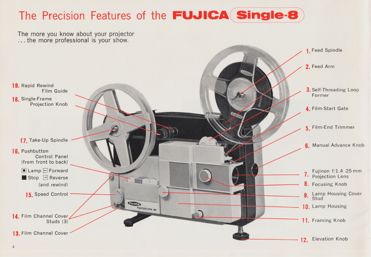
Start the Prjlecller l8. .\‘et (lt‘.\‘lI'L’(l projection l9. Frziniiligg the picture S'NGLE'FRAME PROJECHON
Press the Forward Button ,.m.uj
El and the Lamp 0N Button Speed up the projector by If part of the frame line or 20' fl UT the Mug“ tram?
El (The Lamp ON Butte“ turning the Speed Control the top or bottom of another jjno) up
eannet be depreeeed unless Knob (No. 15) toward “F” frame shows on the screen, ghe Sinhgjtellirame KnOb(;NO' 18)
the Ferward er Reverse (fast). Slow the projection adjust by turning the Fram- .35 aW1€meen ewe .on On.e
Butmn has reviousl been ..side. For normal projection, this
P Y speed by turning the Speed mg Knob (No. ll).
pressed. Th1s1s to prevent Control Knob toward “S” line should be straight back, hori-
accidental Overheating of (Slow) In its midposition’ zontal‘with the baseof theprojec-
tor ’lo stop the projector for
ywr lm'> the knob Sets the projector viewing asingle frame turn the
l7. l~‘o<-us the lens to run at approximately 18 kb.1 ~h h. ’1. .
Tum the F0CL15ing Klwb frames-per-second, which is
<N0- 8) until the $ha1'D@5t the normal speed of your
image is projected on the Qan'1efa_
SCI‘€€I1.
no unt1 te w1te 1ne 1s
straight UP, vertical with the
base of the projector.

A4
‘!\Ta
$.03
lI
Zl. RHMQ-Bi Sllitlil IJY‘<>i@(‘liS 22. Select any imlivitlual A”. To run the lrn llillii R£3"~Y}l!1(ll]1g lm
your film frame wards After the lm has been fully
When you stop the projector If the projector stops slightly Press the Stop Button Ito wound on the take-up reel, press
for viewing asingle frame, abefore or after the exact frame halt the projector. Then, press the stop button on the control
heat shield descends automati- you want to view, move the the Reverse Button and the panel. Pass the end of the lm
cally in front of the lamp. lm forwards or backwards,a Lamp ON Button E. The OVER the Rewind Film Guide
Thisprotects your lm against frame at atime, by turning lm will start to run back- (No. 19) and slip the end onto the
overheating. The shield moves the Manual Advance Knob wards. It may be necessary hub of the empty feed reel. Turn
out of the way when the knob (No. 6). to reframe the picture. To the feed reel manually afew times
is returned to position for resume normal projection, to secure the lm end. Turn the
normal projection. press the stop button, and then speed control fully to “F” and
the forward button. press the Reverse Button E] on
the control panel. After the lm
has been fully rewound on the
feed reel, press the stop button to
halt the projector.

Hints for abetter show
ARRANGE EVERYTHIY\'jG BEF()REH.~\I\’D
Your audience will enjoy your home movie shows much more if
you arrange everything before they arrive. Have the projector set
up, with the light beam properly centered on the screen. Have the
lms you are going to show stacked in proper order, conveniently
at hand. Arrange chairs comfortably, being sure that no one’s head
will interrupt the projection beam. Check to be sure everything is
all right... then, on with the show!
SPLICE AS .\I.*\.\§Y l"Ijl;f\I{%‘ POSSIBIJQ ().\?T() ONAFZ RFIEL
Aminimum number of interruptions makes for amore professional
show. If the subject of your movie is acontinuous one on more
than one lm, splice them together. If there are different subjects,
splice atitle or afoot or more of blank leader between the lms.
If you wish, you can then stop the projector between lms to an-
nounce what’s coming up next. By splicing beforehand you save
time in rewinding and keep your audience’s interest at apeak.
RE\VINl) l"ll..\l AFT ER TH E.§.~l%l()j\j\'i
After you have nished your rst reel, simply transfer the now
empty feed reel to the take-up spindle and place your 2nd loaded
reel on to the feed spindle. .. thread the projector and continue with
the show. Later, after your audience has left, you can rewind the
entire show at your leisure.
KFFP asr-uu Inw ow 11 wt)
Like all electric lamps, the projection lamp will burn out in time.
And, sometimes it may happen just when you want to use your
projector, probably at night, when areplacement will be difcult to
secure. The remedy is simple: keep aspare lamp on hand at all
times. See page 13 “How to replace aburnt out lamp”.

How to replace aburnt out projection lamp
2
\
1
l
I,
pV7 s*~' ——— ——
Open the lamphouse Remove the burned out Replace with afresh lamp Replace the lamphoiise cover
First, disconnect the I"°5°¢ti"" ‘amp Your Fujicascope M2 Projector is equipped Place the lamphouse cover
AC Power Cord. Then The lamp 15 held in 1308i‘ with 8v 50w lamp with built-in reection carefully back in position
loosen the Lamphouse tieh hY three keye that mirror that gives correct illumination and tighten the stud.
Cover Stud (No. 9) fully, engage three S10tS in the quality and effective brightness for color -;‘,u;,r;cat;,m
and liftthe Lamphouse heee Of the lamll Turn lm p1‘O]€C'£1OH. When the lamp needs re- The main gears in your p1_O_
Cover (No. 10,» away. the lamp e0t1hte1“e10e1<" placement, you are recommended to pur- -ector are Ofn 1nand eI,
wise until it comes loose. chase afresh FUJICA SINGLE-8 av sow JY°nVt’
LAMP from the nearest Fujica camera
shop. Place the lamp base on the three
keys, with the clear glass opening point-
ing inwards, toward the front inside corner
of the lamphouse. Press down slightly and
rotate the lamp clockwise until it clicks
into position, with the clear glass opening
pointing straight forward. Jiggle the lamp
to be sure it is secure.
require lubrication.

>-"T,x_‘>¥:_‘W >,_>hA
4%
FU~§%C§8CO¥*£ K
.:=a§=z
s
'§
<
\\
Aperture Plate
Pressure Plate
Sprocket Wheel Cover
Lens Housing
.._----—~ Lens Hood
Focusing Knob
Sprocket Wheel Cover
Film Channel Cover
_,_A ,,A_,~ _“_g_. §;===. _v _______ ..,______ _.-. __.___,-______,_/,,,_._ -~"—1***" ,_ z_ '
A/, -r"“" "“" L3mPH0U5|n8C0V9F
1-1' -‘E=.'3E5;?‘E§55‘5E?'5*'.‘§l-$1‘ ".£=§=-2'_.2;;-:=>§==r"zi‘.I=-% 1§E'§iE§::1:=’-"E1:-:=:= /=: /<
-==;:-==2>e>‘$;z-’;=’a~-éésé ==(‘2§»‘*=z1.=i:/72;»?%?¢=-=-'¢::=@z=¢.#=2:=z:z2 ’~V V
..,/
’~-=5‘--'E=‘===::=: "'1 ».~"E=é?’Y .‘» =' i'§°=;/_-_.4?"-373%?4"'I*==2=1;5E5.§;+2;-’;:5s-5;;.;;:;;;:=;-5::;";g;' -":4"-‘* :5:-;',<;;;~~;.;1_.;_ :5;-~f. .j_ _;_':;3;;;z-5;_,;;; :5-
”‘
<Q°l“*PQ"°°°§?\
1__._.,/ .
-J/:i::.<’;;.=,;;; ‘=2 -"-
1’->,<;;.;».1;g;¢g;=g;":1 I
.7 .>0
... l. -5.;;.,.§.,¢.,,@-,,-4 .v.,-,:,,;._. ~--;;;__=; ;.;-;. .;_. .-’
'
40;15%;:1=:;1;=1;I;;;'=¢:=s<;-4,:-¢3€-F‘-I-?€=;=§=;.-- -- -V ;= ‘-11- .l:;---.-*---<----/ -;-1-12$;-;l ,--=~;<l;.:-;- -1- ;'$<w>b6~5‘x11"54<»'</»§€’¢‘/J '
/4,9’ §Z4~,3<' /<

How to care for your projector
the (“leaning the film channel.
Remove the lamp housing cover as explained on page 13. Remove Push the sprocket wheel covers away from the sprocket wheels.
the lens hood by turning it counter-clockwise until it comes free. Clean in and around the sprocket wheels with the rm brush.
Pull out the focusing knob as far as it will go (an internal spring The lm channel cover comes away from the projector by loosen-
keeps it attached to the lens housing), and slide the lens barrel out ing the three studs (one in front, under the lamphouse cover and
of the lens housing. Use the soft brush to remove dust and alens two in the rear, under the take-up spindle. Clean the channel in
tissue moistened with lens cleaning uid to clean ngerprints and the channel cover by passing the rm brush through it several times.
dirt (never afacial tissue or handkerchief). (‘leanin;:;c the aperture plate and pre.<.~"ure plate
Replacing the lens liacrrel Open the pressure plate by pushing it forward. Insert the rm
With the lens itself facing towards the rear of the projector and the brush from the top, between the pressure plate and the aperture
straight groove at the top, slip the lens barrel into the lens housing. plate. Twist it several times in both directions to remove any dirt
Pull out the focusing knob and push the lens barrel towards the accumulated in the aperture corners. Be careful not to scratch the
back, rotating it slightly until it engages the alignment pin at the nely polished metal surfaces. Close the pressure plate by pushing
top of the inside of the housing. Push it in until the front of the it towards the back.
lens barrel is even with the front of the lens housing. Release the Replace the lm channel cover and the lamphouse cover, replacing
focusing knob and continue pushing the lens barrel until you hear and tightening all studs.
aclick. The lens barrel should now be locked into position with
the feetleihg knell Retete the feetleihg kheb te See it the lehe other? ’IIl.£t.l.l1_l(.‘Tl1fli .?:'.rl§_<3ilf.'(l. iettietrqiteél
barrel mrlves back and rOrrh- Any attempt to adjust, service or repair the projector beyond the
routine maintenance described above may void your guarantee. If
malfunction occurs, or further service is needed, return the projec-
tor to your dealer, or to your nearest Fujica Service Center.
l5

Operating Checklist
i*|<oJi~.:("i‘oi: l4‘.»\ll.I~l '|‘() ()l’El{-\'l‘E; i.,\ j\1f’ i*.\il..s '|‘() i.1<;ii'1‘ i'iioii~:i"|"oi: oi~i~:i:_\'ri~:.<, HIT 1..\ NH’ l)()l~l.\‘ .\()'l‘ l.l(;HT PrO.i@C-
Check AC power cord. Be sure it is rmly plugged into the pro- tion lamp is burnt Out‘ Replace‘ (See page 13>
jector and into the Wan I-eceptaclg Replace 1amp_ ..l’l(‘;l‘l'l{l'I l.\' l§l.l'l{l{l'Il) .e\l\|) i\\'ll.l. .\(“)'l‘ l*()(‘li'.\' .\ll.\l{l’l.Y L€HS
is dirty. (See page 15)
“"l‘l‘{..l?I.l:I>§" ..~\\,lf> l,)lf.\"*.lS B|,..(S)B.\ .l.,\ 'l'.l"l.li1I r.~\\-ll
/\t__1
U)~..,.r
(Dr-‘ Q
%' .inu-
..€1}..._. I
I-'-,-'1iAI._-4
ta-r
%"
'4! .-t /1
Hiii ii‘ uis TU 'l'llli{l;1.\l]) i¥*i~:r;ii*Ji~;im- Clean the apettate plate and eteieeate plate epage 15>
1. Be sure Loop Former is pressed down.
2. Check lm end for square cut and be sure there are no torn
sprocket holes.
3. Be sure you have pressed Forward NOT Reverse button on
control panel.
4. Be sure Single Frame Projection Knob is in correct position,
white line pointing straight backwards.
Sprockets
l~ll.\I J.»\.\l.\' l\ mi. itl().\l.\'ll( '1 iiicmiiixr; ('H-\\.\l".l. --~~e~~ Sprocket Cover
This can be caused by warped or twisted lm, by abroken lm
splice, or by failure to press the loop former before feeding the lm
into the channel. Press the Reverse button to clear the lm out of
the channel. If the lm will not clear, remove the Lamphouse
Cover by loosening the Stud (No. 9) and the Film Channel Cover
by loosening the three Studs (No. 14). This exposes the entire lm
channel. Film may be removed from the sprocket channels and
the lm gate by pushing the sprocket wheel covers away from the 3PF0¢ke’E Cover
sprockets; the pressure plate may be snapped forward, toward the
lens, by pushing its handle, to clear lm out of the gate.
After clearing lm, snap the pi"essm'e plate back to its position.
Pressure Plate Handle
l’l{(_)Jl~l_("l'()li oi_>i:i:,\'i‘_i;.s. m"i' i>ii_"i_‘ii<i:_ l.\' |>i_\i _5in81@f1”am<‘>
p1‘O]€Ct1On knob is not in correct position with white line fully back.
''- 'i"'1 ''''/ 7'1 /Mmt *~~w'a "~ 'I—~—
i'i<o.|i;<"i1iii<. i>oi+..s' _\()_I <_,>ie*.i¢:r<.xi ii. ._\ xi» |'l("'I‘l'l{_l~.L_ 'l.\' l_,.)l_\-1
Replace single frame projection knob to its correct position, white
line straight back.
lo


ACCESSORIES for your projector
%’¥°?‘??<‘*§N
.
];*i[jJ1(:?,»\ SIX(‘l§(),X l"lf.ll(Y\ S1.-\;(;!:[£‘;\ ;\‘l’l.l(‘l-Eli
Plugs inte the Seund Syneh Seeket (Ne 23) en the Tear et the Dre" Since the base material for Single-8 lm is polyester, it is recom
]eet01‘- Keeps the Ftllieaeeepe M2 Pfeleetel‘ in Pefteet eynehrenile‘ mended to use Fujica Single-8 Splicer and Splicing Tape. The con
tien With 3tape Yeeefdel’ tel” Teeefding and Playing beek eynehed ventional liquid cement does not Work for splicing Single-8 lm.
music, commentary, sound effects with your lm.
l8

'\
.1 1'*:'-r-.;-:-.-.-=j ‘1'.{"-.
,
---
iv:
’\
.».' >-.-. _1=;-.--. -
‘<1; »’»-
§
Y
-» ""~"=-*:.=». '~;'~'-_->.=\..-.=-.===.=_-»-_=~... 1.?"
’f=====;.a=.2v==am.-=-..»...
-~-.-.;.~.-_.._».;».-;.:i.1.;».-.;.;~.¢._.;_;.;\§¢>5§1;;;.;5;.;.;;.;.-.;:.--p_.;.;;.;.;..-
1:»:-.;. "_'.-.-.-:1-;»:_--141.;-1-.‘.:»:;.>>.;.:~;.;-:i .->
r>sz-ni.J|x(>.\* zoom PS-F[_'.]IN()_\‘=' man
<f<>.\w'r~:u'n:u 1.1~:.\:s RES()L.LITION LENSES ElTRiREEI»§
Enjoy “Zoom” effect on the High Resolution F/1.4 20 mm Standard 7” reel accepts 600 feet of Fujichrome Single-8 polyester
screen. and 25 mm lenses designed for base lm. Up to 400 feet of other lm bases. Standard 5” reel
The F/1.4 19-32 mm. Zoom big screen projection promise accepts 300 feet of Fujichrome Single-8 polyester base lm. Up to
Converter Lens assures you you abrighter, more beatifully 200 feet of other lm bases. Very useful When used to hold sever-
the brightest and sharpest detailed and larger picture than al different short lms spliced together to make one longer, unin-
zooming image you have ever ever before. terrupted show.
seen.
19

~.
Table of contents
Other FujiFilm Projector manuals