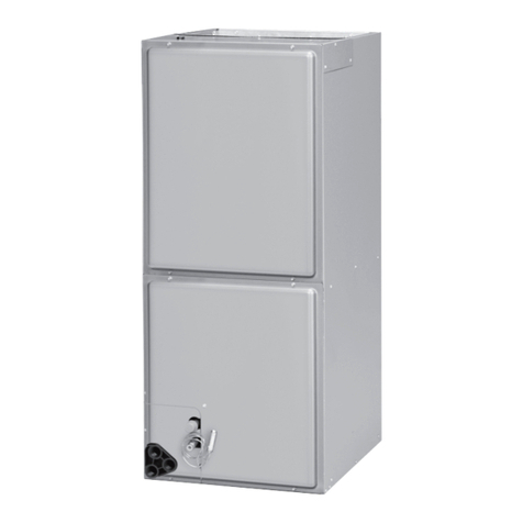
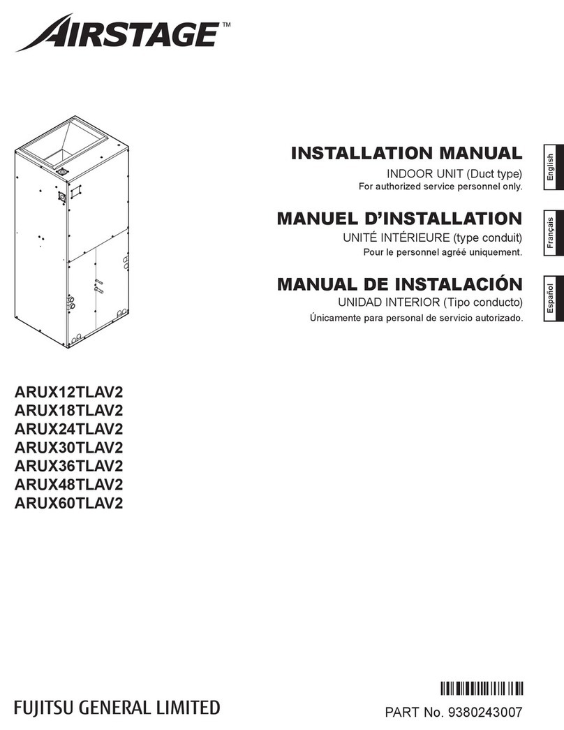
Fujitsu F1T Series User manual

FRONT RETURN AIR HANDLERS
EARTH-FRIENDLY R-410A REFRIGERANT:
(-)F1T High Efficiency w/Aluminum Coil
(-)F1P Standard Efficiency w/Aluminum Coil
INSTALLATION INSTRUCTIONS
92-20521-99-06
SUPERSEDES 92-20521-99-05
sWARNING
!
These instructions are intended as an aid to qualified licensed
service personnel for proper installation, adjustment and
operation of this unit. Read these instructions thoroughly before
attempting installation or operation. Failure to follow these
instructions may result in improper installation, adjustment,
service or maintenance possibly resulting in fire, electrical
shock, property damage, personal injury or death.
ISO 9001:2008
WARNING
These instructions are intended as an aid to qualified licensed
service personnel for proper installation, adjustment and
operation of this unit. Read these instructions thoroughly before
attempting installation or operation. Failure to follow these
instructions may result in improper installation, adjustment,
service or maintenance possibly resulting in fire, electrical
shock, property damage, personal injury or death.
ACCREDITED
,62
!

TABLE OF CONTENTS
2
1.0 SAFETYINFORMATION..............................................................................3
2.0 GENERALINFORMATION...........................................................................5
2.1 ImportantInformationAboutEfficiency&IndoorAir-Quality...............5
2.2 CheckingProductReceived....................................................................5
2.3 ModelNumberNomenclature...............................................................6
2.4 AvailableModels....................................................................................6
2.5 Dimensions&Weights...........................................................................7
2.6 ImportanceofProperIndoor/OutdoorMatch-Ups................................8
2.7 ImportanceofaQualityInstallation.......................................................8
3.0 INSTALLATION..........................................................................................8
3.1 Tools&Refrigerant.................................................................................8
3.1.1 ToolsRequiredforInstalling&ServicingR-410AModels...........8
3.1.2 SpecificationsofR-410A..............................................................8
3.1.3 QuickReferenceGuideforR-410A..............................................9
3.2 Applications............................................................................................9
3.2.1 MountingOptions.......................................................................9
3.2.1.1 WallMount.....................................................................9
3.2.1.2 FrameMount..................................................................9
3.2.1.3 FrontReturnAir............................................................10
3.2.1.4 BottomReturnAir........................................................10
3.2.2 R-22Air-HandlerReplacements................................................10
3.2.3 InstallationinanUnconditionedSpace.....................................10
3.2.4 InstallationinCorrosiveEnvironments.....................................11
3.3 AuxiliaryOverflowPan.........................................................................12
3.4 DrainPanOverflowSwitch...................................................................12
3.5 Clearances............................................................................................12
3.6 Ductwork..............................................................................................13
3.7 ReturnAirFilter....................................................................................13
3.8 OrificeSize:(-)F1P*****PModels........................................................14
3.9 RefrigerantLineConnections&Charging.............................................14
3.9.1 Preparation................................................................................14
3.9.2 LiquidLineFilterDrier...............................................................14
3.9.3 Brazing.......................................................................................14
3.9.4 LeakTesting...............................................................................15
3.9.5 Evacuation.................................................................................15
3.9.6 RefrigerantCharging.................................................................15
3.10 CondensateDrain.................................................................................15
3.11 Thermostat...........................................................................................16
3.12 ElectricalWiring....................................................................................16
3.12.1 ConfiguringUnitfor208VoltPower.........................................16
3.12.2 Grounding..................................................................................17
3.12.3 PowerWiring.............................................................................17
3.12.4 CopperWireSize.......................................................................17
3.12.5 ElectricalData–BlowerMotorOnly–WithoutElectricHeat...18
3.12.6 ElectricalData–WithElectricHeat...........................................18
3.12.7 ElectricHeaterKitSupplementalInformation..........................19
3.12.8 ControlWiring...........................................................................20
3.12.9 Thermostat&ControlWiringConnections...............................20
3.13 Air-Flow................................................................................................20
3.13.1 GeneralAir-FlowOperatingLimits............................................20
3.13.2 SelectingIndoorBlowerMotorSpeed......................................21
3.13.2.1 (-)F1P(PSCMotor)......................................................21
3.13.2.2 (-)F1T(ConstantTorqueECMMotor).........................21
3.13.3 Air-FlowPerformanceData.......................................................22
3.13.3.1 (-)F1P(PSCMotor)......................................................22
3.13.3.2 (-)F1T(ConstantTorqueECMMotor).........................23
4.0 START-UP................................................................................................24
4.1 Pre-StartChecklist................................................................................24
4.2 SystemStart-Up&OperationalCheck-Out..........................................24
4.3 SequenceofOperation.........................................................................24
4.3.1 CoolingHeatMode....................................................................24
4.3.2 ElectricHeatMode....................................................................24
4.3.3 HeatPumpHeatingMode.........................................................25
4.3.4 SupplementalHeatingDuringDefrost......................................25
4.3.5 EmergencyHeat(HeatPump)...................................................25
4.3.6 ThermostatFanSetting.............................................................25
4.4 CorrectingElectricHeatkWforVoltage...............................................25
4.5 CalculatingElectricHeatCapacityinBTUH...........................................25
4.6 CheckingIndoorAir-Flow.....................................................................26
4.6.1 EstimatingCFMUsingExternalStaticPressure.........................26
4.6.2 EstimatingCFMUsingElectricHeatTemperatureRise.............26
4.7 CheckingRefrigerantCharge/ChargingCharts.....................................26

WARNING
If removal of the blower assembly
is required, all disconnect switches
supplying power to the equipment
must be de-energized and locked
(if not in sight of unit) so the field
power wires can be safely removed
from the blower assembly. Failure
to do so can cause electrical shock
resulting in personal injury or death.
(SEE SECTION 7.5.5: BLOWER
WHEEL REPLACEMENT)
1.0 SAFETY INFORMATION
WARNING
Because of possible damage
to equipment or personal injury,
installation, service, and mainte-
nance should be performed by a
trained, qualified service personnel.
Consumer service is recommend-
ed only for filter cleaning/replace-
ment. Never operate the unit with
the access panels removed.
!WARNING (SEE WARNINGS IN REGARD TO DUCTWORK)
Do not install this unit in manufactured (mobile) homes. Improper installation is
more likely in manufactured housing due to ductwork material, size, location,
and arrangement. Installations in manufactured housing can cause a fire result-
ing in property damage, personal injury or death.
EXCEPTION:Manufactured housing installations are approved only with documen-
tation by a recognized inspection authority that the installation has been made in
compliance with the instructions and all warnings have been observed.
!
WARNING
These instructions are intended as an aid to qualified, licensed service per-
sonnel for proper installation, adjustment and operation of this unit. Read
these instructions thoroughly before attempting installation or operation.
Failure to follow these instructions may result in improper installation, adjust-
ment, service or maintenance possibly resulting in fire, electrical shock, prop-
erty damage, personal injury or death.
!
!
WARNING
Disconnect all power to unit before
installing or servicing. More than
one disconnect switch may be
required to de-energize the equip-
ment. Hazardous voltage can cause
severe personal injury or death.
(SEE SECTION 3.12:
ELECTRICAL WIRING)
!WARNING
Duct leaks can create an unbalanced system and draw pollutants such as
dirt, dust, fumes and odors into the home causing property damage. Fumes
and odors from toxic, volatile or flammable chemicals, as well as automo-
bile exhaust and carbon monoxide (CO), can be drawn into the living space
through leaking ducts and unbalanced duct systems causing personal injury
or death (see Figure 1).
• If air-moving equipment or ductwork is located in garages or off-garage stor-
age areas - all joints, seams, and openings in the equipment and duct must
be sealed to limit the migration of toxic fumes and odors including carbon
monoxide from migrating into the living space.
• If air-moving equipment or ductwork is located in spaces containing fuel
burning appliances such as water heaters or boilers - all joints, seams, and
openings in the equipment and duct must also be sealed to prevent depres-
surization of the space and possible migration of combustion byproducts
including carbon monoxide into the living space.
!
3
5.0 COMPONENTS&CONTROLS...................................................................27
5.1 BlowerMotor.......................................................................................27
5.2 MotorRunCapacitor............................................................................27
5.3 BlowerControl......................................................................................27
5.4 Blower...................................................................................................28
5.5 Transformer..........................................................................................28
5.6 IndoorCoil............................................................................................28
6.0 ACCESSORIES&KITS...............................................................................29
6.1 ElectricResistanceHeaterKits..............................................................29
6.2 DrainPanOverflowSwitchKit..............................................................29
6.3 BottomReturnConversionKit..............................................................30
6.4 LouveredCabinetGrille........................................................................30
6.5 DecorativeWallGrille...........................................................................31
7.0 MAINTENANCE.......................................................................................32
7.1 Air-Filter................................................................................................32
7.2 IndoorCoil,DrainPan,DrainLine.........................................................32
7.3 BlowerMotor&Wheel........................................................................32
7.4 MotorLubrication.................................................................................32
7.5 BlowerAssembly,Motor,&BlowerWheelRemoval&Replacement.32
7.5.1 SmallCabinetBlowerAssemblyRemovalProcedure................33
7.5.2 LargeCabinetBlowerAssemblyRemovalProcedure................34
7.5.3 LargeCabinetBlowerMotorOnlyRemovalProcedure............37
7.5.4 MotorReplacement..................................................................39
7.5.5 BlowerWheelReplacement......................................................39
7.6 ReplacementParts................................................................................39
8.0 DIAGNOSTICS..........................................................................................40
9.0 WIRINGDIAGRAMS.................................................................................41
9.1 (-)F1P(3-5kWElectricHeat).................................................................41
9.2 (-)F1P(8-10kWElectricHeat)...............................................................42
9.3 (-)F1T(3-5kWElectricHeat).................................................................43
9.4 (-)F1T(8-10kWElectricHeat)...............................................................44

WARNING
PROPOSITION 65: This appliance
contains fiberglass insulation.
Respirable particles of fiberglass
are known to the State of California
to cause cancer.
All manufacturer products meet
current Federal OSHA Guidelines for
safety. California Proposition 65
warnings are required for certain
products, which are not covered by
the OSHA standards.
California’s Proposition 65 requires
warnings for products sold in
California that contain or produce
any of over 600 listed chemicals
known to the State of California to
cause cancer or birth defects such
as fiberglass insulation, lead in
brass, and combustion products
from natural gas.
All “new equipment” shipped for
sale in California will have labels
stating that the product contains
and/or produces Proposition 65
chemicals. Although we have not
changed our processes, having the
same label on all our products facil-
itates manufacturing and shipping.
We cannot always know “when,
or if” products will be sold in the
California market.
You may receive inquiries from cus-
tomers about chemicals found in, or
produced by, some of our heating
and air-conditioning equipment, or
found in natural gas used with some
of our products. Listed below are
those chemicals and substances
commonly associated with similar
equipment in our industry and other
manufacturers.
• Glass Wool (Fiberglass) Insulation
• Carbon Monoxide (CO).
• Formaldehyde
• Benzene
More details are available at the
websites for OSHA (Occupational
Safety and Health Administration),
at www.osha.gov and the State of
California’s OEHHA (Office of
Environmental Health Hazard
Assessment), at www.oehha.org.
Consumer education is important
since the chemicals and substanc-
es on the list are found in our daily
lives. Most consumers are aware
that products present safety and
health risks, when improperly used,
handled and maintained.
!
CAUTION (SEE SECTION 3.3: AUXILIARY OVERFLOW PAN)
In compliance with recognized codes, it is recommended that an auxiliary
drain pan be installed under all evaporator coils or units containing evaporator
coils that are located in any area of a structure where damage to the building
or building contents may occur as a result of an overflow of the coil drain pan
or a stoppage in the primary condensate drain piping.
!
CAUTION (SEE SECTION 3.2.3: INSTALLATION IN AN UNCONDITIONED SPACE)
When used in cooling applications, excessive sweating may occur when unit
is installed in an unconditioned space. This can result in property damage.
!
WARNING (SEE SECTION 3.7: AIR FILTER)
Do not operate the system without filters. A portion of the dust entrained in
the air may temporarily lodge in the duct runs and at the supply registers. Any
circulated dust particles could be heated and charred by contact with the air
handler elements. This residue could soil ceilings, walls, drapes, carpets and
other articles in the house.
Soot damage may occur with filters in place, when certain types of candles, oil
lamps or standing pilots are burned.
!
NOTICE
Improper installation, or installation not made in accordance with the Underwriters
Laboratory (UL) certification or these instructions, can result in unsatisfactory
operation and/or dangerous conditions and are not covered by the unit warranty.
!
NOTICE
Use of this air-handler during construction is not recommended. If operation
during construction is absolutely required, the following temporary installation
requirements must be followed:
Installation must comply with all Installation Instructions in this manual includ-
ing the following items:
• Properly sized power supply and circuit breaker/fuse
• Air-handler operating under thermostatic control;
• Return air duct sealed to the air-handler;
• Air filters must be in place;
• Correct air-flow setting for application
• Removing the coil and storing it in a clean safe place is highly recommended
until construction is completed and the outdoor unit is installed.
• Clean air-handler, duct work, and components including coil upon completion
of the construction process and verify proper air-handler operating condi-
tions according as stated in this instruction manual.
• NOTE: Electric strip heater elements tend to emit a burning odor for a few
days if dust has accumulated during construction. Heater elements are easily
damaged. Take great care when cleaning them. Low pressure compressed air
is recommended for cleaning elements.
!
4
WARNING (SEE SECTION 3.6: DUCTWORK)
Do not, under any circumstances, connect return ductwork to any other heat
producing device such as fireplace insert, stove, etc. Unauthorized use of such
devices may result in fire, carbon monoxide poisoning, explosion, personal injury
or property damage.
!
WARNING (SEE SECTION 7.0: MAINTENANCE)
Units with circuit breaker(s) meet requirements as a service disconnect
switch, however, if access is required to the line side (covered) of the circuit
breaker, this side of the breaker(s) will be energized with the breaker(s) de-en-
ergized. Contact with the line side can cause electrical shock resulting in per-
sonal injury or death.
!
WARNING (SEE SECTION 3.12.2: GROUNDING)
The unit must be permanently grounded. Failure to do so can result in electri-
cal shock causing personal injury or death.
!

2.0 GENERAL INFORMATION
2.1 IMPORTANT INFORMATION ABOUT EFFICIENCY AND INDOOR
2.1 AIR QUALITY
Central cooling and heating equipment is only as efficient as the duct system that carries
the cooled or heated air. To maintain efficiency, comfort and good indoor air quality, it is
important to have the proper balance between the air being supplied to each room and
the air returning to the cooling and heating equipment.
Proper balance and sealing of the duct system improves the efficiency of the heating
and air conditioning system and improves the indoor air quality of the home by reducing
the amount of airborne pollutants that enter homes from spaces where the ductwork
and/or equipment is located. The manufacturer and the U.S. Environmental Protection
Agency’s Energy Star Program recommend that central duct systems be checked by a
qualified contractor for proper balance and sealing.
2.2 CHECKING PRODUCT RECEIVED
Immediately upon receipt, all cartons and contents should be inspected for transit dam-
age. Units with damaged cartons should be opened immediately. If damage is found, it
should be noted on the delivery documents and a damage claim filed with the delivering
carrier.
After unit has been delivered to the job site, remove the unit from the carton taking care
not to damage the unit. Check the unit rating plate for unit model number, unit size, coil
model, voltage, phase, etc. to assure the unit matches the job specifications.
WARNING
Duct leaks can create an unbalanced system and draw pollutants such as dirt,
dust, fumes and odors into the home causing property damage. Fumes and odors
from toxic, volatile or flammable chemicals, as well as automobile exhaust and
carbon monoxide (CO), can be drawn into the living space through leaking ducts
and unbalanced duct systems causing personal injury or death (see Figure 1).
• If air-moving equipment or ductwork is located in garages or off-garage stor-
age areas - all joints, seams, and openings in the equipment and duct must
be sealed to limit the migration of toxic fumes and odors including carbon
monoxide from migrating into the living space.
• If air-moving equipment or ductwork is located in spaces containing fuel
burning appliances such as water heaters or boilers - all joints, seams, and
openings in the equipment and duct must also be sealed to prevent depres-
surization of the space and possible migration of combustion byproducts
including carbon monoxide into the living space.
!
NOTICE
Improper installation, or installation not made in accordance with the Underwriters
Laboratory (UL) certification or these instructions, can result in unsatisfactory
operation and/or dangerous conditions and are not covered by the unit warranty.
!
5
NOTICE
In compliance with recognized codes, it is recommended that an auxiliary
drain pan be installed under all evaporator coils or units containing evaporator
coils that are located in any area of a structure where damage to the building
or building contents may occur as a result of an overflow of the coil drain pan
or a stoppage in the primary condensate drain piping.
!
FIGURE 1
MIGRATION OF DANGEROUS SUBSTANCES, FUMES, AND ODORS INTO LIVING SPACES

2.3 MODEL NUMBER EXPLANATION
(-) F 1 P 24 21 S P A N J A N 00 ***
MINOR SERIES
A = FIRST
VOLTAGE
J = 208/240/1/60
EFFICIENCY
S = STANDARD
M = MEDIUM
STAGE OF AIR FLOW
1 = SINGLE
PRODUCT CATEGORY
F = FRONT RETURN AIR HANDLER
MOTOR TYPE
P = PSC T= CONSTANT TORQUE
CONTROLS
N = NON-COMMUNICATING
MAJOR SERIES
A = FIRST
NOMINAL CAPACITY
18 = 18,000 BTU/H 30 = 30,000 BTU/H
24 = 24,000 BTU/H* 36 = 36,000 BTU/H*
BRAND
METERING DEVICE
T = TXV P = PISTON
WIDTH
21 = 21.5” 24 = 24”
OPTION CODE
BLANK = NONE
FACTORY HEAT
00 = NO HEAT 08 = 8 kW
03 = 3kW 10 = 10 kW
05 = 5 kW
DISCONNECT
B = BREAKER N = NONE
FIGURE 2
MODEL NUMBER EXPLANATION
6
2.4 AVAILABLE MODELS: J VOLTAGE
(-)F1P1821SPAN
(-)F1P2421SPAN
(-)F1P3024SPAN
(-)F1P3624SPAN
(-)F1P1821STAN
(-)F1P2421STAN
(-)F1P3024STAN
(-)F1P3624STAN
(-)F1T3624MTAN
(-)F1T2421MTAN
* FOR (-)F1T
24 = 18,000 / 24,000 BTU/H
36 = 30,000 / 36,000 BTU/H

7
2.5 DIMENSIONS & WEIGHTS
DIMENSIONAL DATA
MODEL
(B)
UNIT
HEIGHT
IN. [mm]
(C)
UNIT
DEPTH
IN. [mm]
(D) RETURN
AIR OPENING
WIDTH IN.
[mm]
(E) RETURN
AIR OPENING
HEIGHT IN.
[mm]
AIRFLOW
COIL / [L/s]
UNIT WEIGHT /
SHIPPING WEIGHT
LBS. / [kg]
(-)F1P24 36
[914.4]
17
[431.8]
17-7/16
[442.9]
800
[378]
36
[914.4]
21
[533.4]
21-3/8
[542.9]
1200
[566]
600/800
[283/378]
17
[431.8]
17-7/16
[442.9]
36
[914.4]
(-)F1P36
(-)F1T24
1000/1200
[472/566]
21
[533.4]
21-3/8
[542.9]
36
[914.4]
(A)
UNIT
WIDTH
IN. [mm]
21-1/2
[546.1]
24
[609.6]
21-1/2
[546.1]
24
[609.6]
(-)F1T36
(-)F1P30 36
[914.4]
21
[533.4]
21-3/8
[542.9]
1000
[472]
24
[609.6]
(-)F1P18 36
[914.4]
17
[431.8]
20
[508]
23
[584.2]
20
[508]
23
[584.2]
23
[584.2]
20
[508]
17-7/16
[442.9]
600
[283]
80/90
[36]/[41]
80/90
[36]/[41]
95/105
[43]/[48]
95/105
[43]/[48]
80/90
[36]/[41]
95/105
[43]/[48]
21-1/2
[546.1]
FIGURE 3
DIMENSIONS AND WEIGHTS
NOTE: 24” CLEARANCE REQUIRED
IN FRONT OF UNIT FOR FILTER
AND COIL MAINTENANCE.
HIGH VOLTAGE CONNECTION,
1-3/8” AND 7/8” KNOCKOUTS
VAPOR LINE CONNECTION
COPPER (SWEAT)
FRONT RETURN SHOWN.
UNITS MAY ALSO BE INSTALLED
AS BOTTOM RETURN.
SEE THE APPLICATIONS SECTION
FOR MORE DETAIL.
ALL UNITS ARE CONFIGURED FOR
VERTICAL UPFLOW. UNITS CANNOT
BE INSTALLED IN ANY OTHER
CONFIGURATION.
SUPPLY AIR
E
C
RETURN AIR
OPENING
D
LIQUID LINE CONNECTION
COPPER (SWEAT)
FLANGES FOR FIELD
INSTALLED DUCTWORK
B
A

8
2.6 IMPORTANCE OF PROPER INDOOR/OUTDOOR MATCH-UPS
To assure many years of reliable operation and optimum customer comfort and to assure
the outdoor unit warranty remains valid, an air-handler model should be selected that is
properly matched to the outdoor unit. This is especially critical for heat pump systems to
assure proper refrigerant charge balance between the cooling and heating modes. The
recommended approach is to select an air-handler model that has an AHRI match with
the outdoor unit. Refer to the AHRI directory at www.ahridirectory.org to confirm the
air-handler and outdoor unit are a certified combination in the AHRI Directory.
2.7 IMPORTANCE OF QUALITY INSTALLATION
A quality installation is critical to assure safety, reliability, comfort, and customer satis-
faction. Strict adherence to applicable codes, the information in this installation manual,
the outdoor unit installation manual, and the thermostat installation manual are key to a
quality installation. Read the entire instruction manuals before starting the installation.
IMPORTANT: This product has been designed and manufactured to meet certified
AHRI capacity and efficiency ratings with the appropriate outdoor units. However, prop-
er refrigerant charge, proper airflow, and refrigerant line sizing are critical to achieve
optimum capacity and efficiency and to assure reliable operation. Installation of this
product should follow the manufacturer’s refrigerant charging and airflow instructions
located in the outdoor unit installation instructions and the charging chart label affixed to
the outdoor unit. Failure to confirm proper charge and airflow may reduce energy effi-
ciency and shorten equipment life.
The equipment has been evaluated in accordance with the Code of Federal
Regulations, Chapter XX, Part 3280.
Install the unit in accordance with applicable national, state, and local codes. Latest edi-
tions are available from: “National Fire Protection Association, Inc., Batterymarch Park,
Quincy, MA 02269.” These publications are:
• ANSI/NFPA No. 70-(Latest Edition) National Electrical Code.
• NFPA90A Installation of Air Conditioning and Ventilating Systems.
• NFPA90B Installation of warm air heating and air conditioning systems.
Install the unit in such a way as to allow necessary access to the coil/filter rack and
blower/control compartment.
3.0 INSTALLATION
3.1 TOOLS & REFRIGERANT
3.1.1 TOOLS REQUIRED FOR INSTALLING AND SERVICING R-410A MODELS
Manifold Sets:
• Up to 800 PSIG High-Side
• Up to 250 PSIG Low-Side
• 550 PSIG Low-Side Retard
Manifold Hoses:
• Service Pressure Rating of
800 PSIG
Recovery Cylinders:
• 400 PSIG Pressure Rating
• Dept. of Transportation
4BA400 or BW400
3.1.2 SPECIFICATIONS OF R-410A
Application: R-410A is not a drop-in replacement for R-22. Equipment designs must
accommodate its higher pressures. It cannot be retrofitted into R-22 heat pumps.
Physical Properties: R-410A has an atmospheric boiling point of -62.9°F [-52.7°C] and
its saturation pressure at 77°F [25°C] is 224.5 psig.
Composition: R-410A is a near-azeotropic mixture of 50% by weight difluoromethane
(HFC-32) and 50% by weight pentafluoroethane (HFC-125).
Ambient and Tube
Thermometers
Manifold
Gauge
Set
Brazing
Rods
Torch Nitrogen
Reclaimer
Recovery
Cylinders
Allen Wrench
Crescent Wrench
NOTICE
R-410A systems operate
at higher pressures than
R-22 systems. Do not
use R-22 service equip-
ment or components on
R-410A equipment.
!

9
Pressure: The pressure of R-410A is approximately 60% (1.6 times) greater than
R-22. Recovery and recycle equipment, pumps, hoses, and the like must have design
pressure ratings appropriate for R-410A. Manifold sets need to range up to 800 psig
high-side and 250 psig low-side with a 550 psig low-side retard. Hoses need to have a
service pressure rating of 800 psig. Recovery cylinders need to have a 400 psig service
pressure rating, DOT 4BA400 or DOT BW400.
Combustibility: At pressures above 1 atmosphere, a mixture of R-410A and air can
become combustible. R-410A and air should never be mixed in tanks or supply
lines or be allowed to accumulate in storage tanks. Leak checking should never
be done with a mixture of R-410A and air. Leak-checking can be performed safely
with nitrogen or a mixture of R-410A and nitrogen.
3.1.3 QUICK-REFERENCE GUIDE FOR R-410A
• R-410A refrigerant operates at approximately 60% higher pressure (1.6 times) than
R-22. Ensure that servicing equipment is designed to operate with R-410A.
• R-410A refrigerant cylinders are light rose in color.
• R-410A, as with other HFCs, is only compatible with POE oils.
• Vacuum pumps will not remove moisture from POE oil used in R-410A systems.
• R-410A systems are to be charged with liquid refrigerants. Prior to March 1999,
R-410A refrigerant cylinders had a dip tube. These cylinders should be kept upright
for equipment charging. Post-March 1999 cylinders do not have a dip tube and should
be inverted to ensure liquid charging of the equipment.
• Do not install a suction line filter drier in the liquid line.
• A factory-approved outdoor liquid line filter drier is shipped with every unit and must
be installed in the liquid line at the time of installation. If only the air-handler is being
replaced on an existing system, the existing filter drier must be replaced at the time
of installation with a field supplied filter drier. IMPORTANT: A bi-flow filter drier must
be used for heat pump applications. Filter driers must be rated for minimum working
pressure of 600 psig. The filter drier will only have adequate moisture-holding capaci-
ty if the system is properly evacuated.
• Desiccant (drying agent) must be compatible for POE oils and R-410A refrigerant.
3.2 APPLICATONS
• Vertical Upflow is the factory configuration for all models (see Figure 3).
• If return air is to be ducted, install duct flush with floor. Use fireproof resilient gasket
1/8 to 1/4 in. thick between duct, unit and floor. Set unit on floor over opening.
3.2.1 MOUNTING OPTIONS
The air handler comes standard with two different options for mounting, wall mount or
frame mount. Both mounting options require the unit to be level from side to side and
from front to back in order to allow condensate to properly drain from the unit. Failure to
do this will result in condensate to leak out from the unit potentially causing structural
damage to the surrounding support structures, dry wall, carpet, etc. around the unit.
Also, both mounting structures require the ability to accommodate a minimum of 150 lb.
load. Failure to do this will cause damage to the support structure and potentially dam-
age the unit.
3.2.1.1 WALL MOUNT
The air handler comes standard with a wall mounting bracket and air handler mounting
bracket. Reference Figure 5 for more detail.
1. Remove the wall mounting bracket from the back of the unit by removing one screw
which attaches the bracket to the air handler. Note: Discard the screw after you have
removed the wall mounting bracket.
2. Install bracket one the wall by using 6 wood screws (not provided). Make sure the
bracket is level in order to provided proper drainage from the unit. Note: Do not attach
the wall mounting bracket into unsupported dry wall. Make sure that the wood screws
are going into a structure that can support a minimum of 150 lb load.
3. Lift the air handler above the wall mounting bracket and attached the unit to the
installed bracket. Reference Figure 5.
3.2.1.2 FRAME MOUNT
The air handler comes with 8 clearance holes 4 on each side. These holes are used to
mount the air handler inside of a frame structure (see Figure 6). When mounting in this
fashion, make sure that the wood screws are mounted from within the air handler and not
outside of the unit. Installing the screws from the outside could cause damage to the coil.

3.2.1.3 FRONT RETURN AIR
Most applications for this style of air-handler bring the return air through into the front
of the unit from the conditioned space with no return duct. The unit is shipped from the
factory to accommodate this type of installation with no modications. Louvered cabinet
grilles and decorative wall grilles are available as an accessory to facilitate front return
installations. (See Sections 6.4 and 6.5)
3.2.1.4 BOTTOM RETURN AIR
Should the application require the return air to enter the unit from the bottom, the unit
can be easily converted to bottom return using an accessory kit (RXHK series) found in
Section 6.3 of this manual. The conversion involves removing the block-off plate shipped
installed in the bottom of the unit and installing the front door that comes with the con-
version kit. Once converted, the unit can be mounted on a bottom return air platform or
connected to a bottom return duct. If an external lter rack is installed, the unit’s internal
lter must be removed.
3.2.2 R-22 AIR-HANDLER REPLACEMENTS
(-)F1P models can be used to replace an air-handler in applications using R-22 refriger-
ant with a simple orice (piston) change. Refer to Section 3.8 for recommended orice
sizes for R-22 systems.
3.2.3 INSTALLATION IN AN UNCONDITIONED SPACE
The exterior cabinet of an air handler has a greater risk of sweating when installed in an
unconditioned space than when it is installed in the conditioned space. This is primarily
due to the temperature of the conditioned air moving through the air handler and the
air circulating around the unit where it is installed. For this reason, the following is rec-
ommended for all air handler applications, but special attention should be paid to those
installed in unconditioned spaces:
• Duct sizing and airflow are critical and must be based on the equipment selected.
• Supply and return duct attachment: If other than the factory flanges are used, the
attachment of ducting must be insulated and tight to prevent sweating.
10
FIGURE 4
DIMENSIONS FOR DUCTWORK & DRAINS

• No perimeter supply flanges are provided. If a full perimeter supply duct is used, it is
the responsibility of the installer to provide duct flanges as needed, to secure and seal
the supply duct to prevent air leakage and the sweating that will result.
• Apply caulking around all cabinet penetrations such as power wires, control wires,
refrigerant tubing and condensate line where they enter the cabinet. Seal the power
wires on the inside where they exit conduit opening. Sealing is required to prevent air
leakage into the unit which can result in condensate forming inside the unit, control
box, and on electrical controls. Take care not to damage, remove or compress insula-
tion when applying the caulk.
• In some cases, the entire air handler can be wrapped with insulation. This can be
done as long as the unit is completely enclosed in insulation, sealed and service
access is provided to prevent accumulation of moisture inside the insulation wrap.
• An auxiliary overflow pan is recommended to protect the structure from excessive
cabinet sweating or a restricted coil drain line. (See Section 3.3)
• If an electric heater kit is installed, be sure the breaker or disconnect cover is sealed
tightly to the door panel.
3.2.4 INSTALLATION IN CORROSIVE ENVIRONMENTS
The metal parts of this unit may be subject to rust or deterioration if exposed to a cor-
rosive environment which can shorten its life. In addition to exposure to the exterior of
the cabinet, chemical contaminants inside the building that can be drawn into the unit
from the return air grille and attack structural metal parts, electrical components and the
indoor coil, causing premature failure of the unit. If the unit is to be installed in an area
where contaminants are likely to be a problem, special attention should be given to iso-
late the unit and return grille from contaminants.
11
FIGURE 5
WALL MOUNT

FIGURE 6
FRAME MOUNT
12
3.3 AUXILIARY OVERFLOW PAN
To comply with building codes, an auxiliary overow pan must installed under all equip-
ment containing evaporator coils that are located in any area of a structure where dam-
age to the building or building contents may occur as a result of an overow of the coil
drainpan or a stoppage in the primary condensate drain piping. Aftermarket overow
pans are available or one can be fabricated in the eld as required.
3.4 DRAIN PAN OVERFLOW SWITCH
An overow switch is available as a factory option (option code 417) or a eld installed
accessory kit (RXHK-A01- See Section 6.2) that will shut the outdoor unit off to prevent
the water level in the unit drainpan from rising above a safe level. As with the auxiliary
overow pan, most building codes require a drain overow switch for installations where
structure damage can occur as a result of an overow of the unit condensate drainpan.
3.5 CLEARANCES
• All units are designed for “0” inches clearance to combustible material on all cabinet
surfaces.
• Units with electric heat require a one inch clearance to combustible material for the
first three feet of supply plenum and ductwork.
• All units require 24 inches minimum access to the front of the unit for service.
• These units may be installed in either ventilated or non-ventilated spaces.

13
3.6 DUCTWORK
Field ductwork must comply with the National Fire Protection Association NFPA 90A,
NFPA 90B and any applicable local ordinance.
Sheet metal ductwork run in unconditioned spaces must be insulated and covered with a
vapor barrier. Fibrous ductwork may be used if constructed and installed in accordance
with SMACNA Construction Standard on Fibrous Glass Ducts. Ductwork must comply
with National Fire Protection Association as tested by U/L Standard 181 for Class I Air
Ducts. Check local codes for requirements on ductwork and insulation.
• Duct system must be designed within the range of external static pressure the unit
is designed to operate against. It is important that the system airflow be adequate.
Make sure supply and return ductwork, grills, special filters, accessories, etc. are
accounted for in total resistance. See airflow performance tables in this manual.
• Design the duct system in accordance with “ACCA” Manual “D” Design for Residential
Winter and Summer Air Conditioning and Equipment Selection. Latest editions are
available from: “ACCA” Air Conditioning Contractors of America, 1513 16th Street,
N.W., Washington, D.C. 20036. If duct system incorporates flexible air duct, be sure
pressure drop information (straight length plus all turns) shown in “ACCA” Manual
“D” is accounted for in system.
• Supply plenum is attached to the 3/4” duct flanges supplied with the unit. Attach
flanges around the blower outlet.
IMPORTANT: If an elbow is included in the plenum close to the unit, it must not be
smaller than the dimensions of the supply duct flange on the unit.
• IMPORTANT: The front flange on the return duct if connected to the blower casing
must not be screwed into the area where the power wiring is located. Drills or sharp
screw points can damage insulation on wires located inside unit.
• Secure the supply and return ductwork to the unit flanges, using proper fasteners for
the type of duct used and tape the duct-to-unit joint as required to prevent air leaks.
3.7 RETURN AIR FILTER
An internal lter rack is provided with this unit and is sufcient for most applications
using this type of air-handler. If an external means of ltering the return air is required,
the external lters should be sized for a maximum of 300 feet/min air velocity or the
maximum velocity recommended by the type of lter installed. One or more return air l-
ter grilles, a lter rack attached to unit return air intake, or a lter rack installed between
a sealed return air platform and the return duct are all acceptable means of ltration. All
return ducts must be ltered, either at each return grille or at a common lter near or
inside the unit.
Important: Do not install a return air lter grille if a lter rack is installed at the unit or
the internal lter is used. Do not install a lter in the supply duct system.
Filter type, sizing, and placement are critical to heating and cooling system performance.
Reduced air-ow can shorten the life of system components such as the compressor,
indoor coil, heater elements, over temperature limits, and relays. As lters near the end
of their useful life, the pressure drop through them increases. Therefore, it is important
to factor the “end of life” (dirty) pressure drop lters the external static pressure of the
duct system when selecting blower speeds and designing ductwork to assure the sys-
tem is operating at the design CFM and system reliability is not compromised. Always
verify that the system’s air-ow is within specications by performing a temperature rise
(heating mode) and temperature drop (cooling mode) with all lters in place.
Important: High efciency pleated lters and electronic air cleaners typically have
signicantly higher pressure drop than standard efciency berglass lters, especially
when they get dirty. Do not use high efciency lters or electronic air cleaners unless
adequate lter area is provided to lower the lter pressure drop to an acceptable level.
WARNING
Do not, under any circumstances, connect return ductwork to any other
heat producing device such as fireplace insert, stove, etc. Unauthorized
use of such devices may result in fire, carbon monoxide poisoning, explo-
sion, personal injury or property damage.
!

14
INDOOR UNIT FACTORY
PISTON
SEER RATING
OD UNIT
NOMINAL
TONS REFRIGERANT ORIFICE
SIZE
13 1.5 R410a 0.047
14 1.5 R410a 0.049
(-)F1P1821SPAN 0.047 13 1.5 R22 0.049
12 1.5 R22 0.051
10 1.5 R22 0.053
13 2 R410a 0.053
14 2 R410a 0.057
(-)F1P2421SPAN 0.053 13 2 R22 0.057
12 2 R22 0.061
10 2 R22 0.063
13 2.5 R410a 0.061
14 2.5 R410a 0.063
(-)F1P3024SPAN 0.061 13 2.5 R22 0.065
12 2.5 R22 0.065
10 2.5 R22 0.065
13 3 R410a 0.065
14 3 R410a 0.068
(-)F1P3624SPAN 0.065 13 3 R22 0.069
12 3 R22 0.070
10 3 R22 0.070
3.8 ORIFICE SIZE: (-)F1P*****P MODELS
(-)F1P*****P air-handlers are equipped with a xed orice (piston) sized for a typical 13
SEER R-410A outdoor unit. The piston must be changed if the outdoor unit has a higher
or lower efciency or if the system is using R-22 as a refrigerant. The chart below shows
recommended orice sizes for various efciencies for R-410A and R-22.
The orifice is located in the indoor coil distributor body and can be accessed by
unscrewing the distributor body. Replacing the Teon gasket is recommended when
changing the orice to assure a leak free joint. Orices and gaskets are available from
most local wholesale distributors.
3.9 REFRIGERANT LINE CONNECTIONS & CHARGING
3.9.1 PREPARATION
The coil is shipped with a low pressure (5-10 psig) charge of dry nitrogen which will be
released when the rubber plugs are removed. Leave the rubber plugs in the refrigerant
connection stubs on the air-handler until the refrigerant lines are ready to be brazed to
the refrigerant connection stubs to prevent contaminants from entering the coil. Clean
the ends of the tubing and coil connection stubs (inside and outside) with an alcohol
wipe before inserting the line set tubes into the coil connection stubs to assure a quality
leak-free braze joint.
Refer to the outdoor unit installation instructions for details on refrigerant line sizing and
installation. Be sure to follow long line length guidelines if they apply.
Route the refrigerant tubing in a manner than does not block service access to the front
of the air-handler.
3.9.2 LIQUID LINE FILTER DRIER
A new liquid filter drier must be installed every time any part of the system has been
open to the atmosphere, even if it’s for a short period of time. The filter drier should be
installed close to the air-handler for a system started up in the cooling mode and near
the outdoor unit for a heat pump system started up in the heating mode. This allows the
filter drier to catch any contaminants in the liquid line before they can enter the indoor or
outdoor TXV or piston inlet screen.
3.9.3 BRAZING
Air inside the tubing and coil should be displaced with dry nitrogen prior to the brazing
process to prevent the formation of harmful copper oxide inside the tubing. It is very
important not to pressurize the system with nitrogen while brazing or pin-hole leaks will
form in the braze joint. This is accomplished by removing the gauge port valve core on
one of the outdoor unit service valves to allow the pressure to be relieved as the heat-
ed nitrogen expands. Fill the system with dry nitrogen through the other service valve
gauge port and then turn the nitrogen flow off just before brazing is begun.

15
Protect the TXV, copper to aluminum suction header joint, and outdoor unit service
valves from overheating using a wet rag or heat sink compound. Leave the wet rag or
heat sink material in place until the joint and surrounding tubing cools down to a safe
temperature. Double tip torches can help minimize brazing time and heat conduction
to the heat sensitive components if the flame is turned down and held on the joint just
long enough to make the braze joint. With both single and double tip torches, turning
the flame up too much and keeping the flame on the joint too long will damage the heat
sensitive components even when a wet rag or heat sink compound is used.
Use a sheet metal shield to protect the cabinet’s finish from the torch flames during the
brazing process. The vapor line insulation should be pushed back on the line about 12
inches from the joint and retained to prevent it from igniting or melting during the brazing
process.
After the refrigerant brazed connections are made at the air-handler and the tubing has
cooled down sufficiently, seal the air gap around the connection stubs with the foam
rubber gasket included in the air-handler parts bag. Peel the self-adhesive backing off
of the foam gasket and position it around the stubs with the adhesive side toward the
cabinet, then press it firmly against the cabinet. The gasket is split to allow it to go over
the stubs after the refrigerant tubes are brazed to the stubs.
After the foam gasket has been installed, the vapor line insulation should be pulled back
in place so it contacts the air-handler cabinet to prevent condensate from forming on the
cold tube and dripping off. A loosely fitting zip-tie placed around the insulation ½” from
the end can be used to hold it in place so it doesn’t move away from the cabinet.
3.9.4 LEAK TESTING
After all braze joints are completed, replace the valve core removed when purging with
nitrogen and then leak test the system by pressurizing to 150 psig with dry nitrogen and
allow the system to sit for at least 15 minutes (longer if possible) to assure the pressure
does not drop.
3.9.5 EVACUATION
If no leaks are detected, evacuate the system down to 500 microns or below before
charging the system or opening the service valves on the outdoor unit which will release
the charge stored in the outdoor unit into the line set and air-handler coil. Failure to
reach 500 microns of vacuum is a sign of a leak or excessive moisture inside the system.
3.9.6 REFRIGERANT CHARGING
Once the evacuation process is completed, break the vacuum with the refrigerant from a
refrigerant cylinder or with refrigerant stored in the outdoor unit by opening the outdoor
unit service valves. The charging process cannot be completed until the remaining
steps in the installation process are completed and the indoor air-flow is adjusted to the
proper level. See Section 4.7 for further details.
3.10 CONDENSATE DRAIN
Consult local codes or ordinances for specific requirements.
IMPORTANT: When making drain fitting connections to the drain pan, use a thin layer of
Teflon paste, silicone or Teflon tape and install hand tight.
IMPORTANT: When making drain fitting connections to drain pan, do not overtighten.
Overtightening fittings can split pipe connections on the drain pan.
• Install drain lines so they do not block service access to front of the unit. Minimum
clearance of 24 inches is required for filter, coil or blower removal and service access.
• Although the condensate drain pan is designed is designed to be self draining, it is
recommended that the air-handler cabinet be pitched slightly downward toward the pri-
mary drain connection to assure the condensate drains completely from the drain pan.
The downward pitch should be approximately 1/8” per foot and in both axes.
• Do not reduce drain line size less than connection size provided on condensate drain
pan.
• All drain lines must be pitched downward away from the unit a minimum of 1/8” per
foot of line to ensure proper drainage.
• Do not connect condensate drain line to a closed or open sewer pipe. Run conden-
sate to an open drain or outdoors.
• The drain line should be insulated where necessary to prevent sweating and damage
due to condensate forming on the outside surface of the line.
• Make provisions for disconnecting and cleaning of the primary drain line should it
become necessary. Install a 3 in. trap in the primary drain line as close to the unit as
possible. Make sure that the top of the trap is below connection to the drain pan to
allow complete drainage of pan (See Figure 7).

16
• The auxiliary drain line should be run to a place where it will be noticeable if it becomes
operational. The building occupant should be warned that a problem exists if water
should begin running from the auxiliary drain line. An auxiliary drain shut-off switch can
be installed in lieu of an auxiliary drain line. The shut-off switch should be wired into the
control circuit so the outdoor unit shuts down should the switch detect water.
• Plug the unused drain connection with the plugs provided in the parts bag, using a
thin layer of teflon paste, silicone or teflon tape to form a water tight seal.
• Test the condensate drain pan and drain line after installation is complete. Pour water
into drain pan, enough to fill drain trap and line. Check to make sure drain pan is
draining completely, no leaks are found in drain line fittings, and water is draining from
the open end of the primary drain line.
3.11 THERMOSTAT
See instructions for the condensing unit or heat pump for recommended room thermostats.
• On units with one electric heat sequencer (TD1) (see wiring diagram for electric heat-
er), heat anticipator setting should be .16.
• On units with two electric heat sequencers (TD1& TD2) (see wiring diagram for elec-
tric heater), heat anticipator setting should be .32 if both are connected to same stage
on thermostat. Setting should be .16 if (TD1& TD2) are connected to separate stages.
NOTE: Some thermostats contain a fixed, non-adjustable heat anticipator.
Adjustment is not permitted.
• The thermostat should be mounted 4 to 5 feet above the floor on an inside wall of the
living room or a hallway that has good air circulation from the other rooms being con-
trolled by the thermostat. It is essential that there be free air circulation at the location
of the same average temperature as other rooms being controlled. Movement of air
should not be obstructed by furniture, doors, draperies, etc. The thermostat should
not be mounted where it will be affected by drafts, hot or cold water pipes or air ducts
in walls, radiant heat from fireplace, lamps, the sun, T.V. or an outside wall. See
instruction sheet packaged with thermostat for mounting and installation instructions.
3.12 ELECTRICAL WIRING
Field wiring must comply with the National Electric Code (C.E.C. in Canada) and any
applicable local ordinance.
3.12.1 CONFIGURING UNIT FOR 208 VOLT POWER
The control transformer in 208/240V air-handlers must be congured in the eld to oper-
ate on a 208 volt electrical supply to assure adequate control voltage (24+ volts) with the
reduced supply voltage. The units are shipped from the factory for 230-240 volt appli-
cations. For 208 volt applications, disconnect electrical power to the unit and remove
the blower/control access panel on the front of the unit. Then remove the insulated cap
from the 208 volt transformer terminal and move the BLACK wires that are connected to
the 240 volt transformer terminal to the 208 volt transformer terminal. Plug the insulated
cap onto the transformer 240V terminal.
FIGURE 7
CONDENSATE DRAIN TRAP
ST-A1244-01-01
WARNING
Disconnect all power to unit before installing or servicing. More than one dis-
connect switch may be required to de-energize the equipment. Hazardous volt-
age can cause severe personal injury or death.
!

17
The PSC indoor blower motor in the (-)F1P air-handlers must also be congured for 208
volt applications to assure full air-ow delivery at the reduced voltage. This step is not
required on (-)F1T air-handlers since they have constant torque ECM motors. To con-
gure the PSC motor in (-)F1P air-handlers for 208 volt applications, unplug the PURPLE
motor lead connected to the insulated terminal on the end of the ORANGE wire coming
from the transformer. Pull the cap out of the insulated terminal on end of the YELLOW
motor lead and plug the cap into the terminal on the end of the PURPLE motor lead to
eliminate the possibility of an electrical short. Plug the YELLOW motor lead into the ter-
minal on the end of the ORANGE wire from the transformer. Secure the indoor blower
motor wiring with zip ties to assure they can’t come in contact with the blower wheel.
Replace the blower/control box access panel when the above is complete before apply-
ing electrical power to the unit.
3.12.2 GROUNDING
• Grounding may be accomplished by grounding metal conduit when installed in accor-
dance with electrical codes to the unit cabinet.
• Grounding may also be accomplished by attaching ground wire(s) to ground lug(s)
provided in the unit wiring compartment.
• Ground lug(s) are located close to wire entrance on left side of unit.
• Use of multiple supply circuits require grounding of each circuit to lug(s) provided in unit.
3.12.3 POWER WIRING
It is important that proper electrical power is available for connection to the unit model
being installed. See the unit nameplate, wiring diagram and electrical data in the installa-
tion instructions.
• If required, install a branch circuit disconnect of adequate size, located within sight of,
and readily accessible to the unit.
• IMPORTANT: Units with electric heater kits installed may be equipped with one, two,
or three 30/60 amp circuit breakers. These breaker(s) protect the internal wiring in the
event of a short circuit and serve as a disconnect. Circuit breakers installed within the
unit do not provide over-current protection of the supply wiring and therefore may be
sized larger than the branch circuit protection.
• Supply circuit power wiring must be 75°C minimum copper conductors only. See
Electrical Data in Sections 3.12.5 and 3.12.6 for ampacity, wire size and circuit pro-
tector requirement. Supply circuit protective devices may be either fuses or “HACR”
type circuit breakers.
• Field power wiring may be connected to either the right, left side or top. Three 7/8”,
13/32”, 131/32” dia. concentric knockouts are provided for connection of power wiring to
unit.
• Field power wiring is to be connected to the power terminal block in unit control com-
partment.
• For units equipped with an electric heater kit, field power wiring is to be connected to
the heater kit breaker, terminal block, or pullout disconnect terminals and the power
wiring pigtail from the heater kit is to be connected to the unit power terminal block in
the unit control compartment. Refer to installation instructions provided with the heat-
er kit for additional details.
WARNING
The unit must be permanently grounded. Failure to do so can result in electri-
cal shock causing personal injury or death.
!
S
U
P
P
L
Y
W
I
R
E
L
E
N
G
T
H
F
E
E
T
SUPPLY CIRCUIT AMPACITY
NOTE: WIRE BASED ON COPPER CONDUCTORS 75°C MINIMUM RATING.
FOR MORE THAN 3 CONDUCTORS IN A RACEWAY OR CABLE, SEE
N.E.C. FOR DERATING THE AMPACITY OF EACH CONDUCTOR.
12
12
14
14
15
10
10
12
12
20
8
10
10
10
25
8
10
10
10
30
8
8
8
8
35
6
8
8
8
40
6
6
8
8
45
6
6
6
6
50
4
6
6
6
60
4
4
4
4
70
3
4
4
4
80
3
3
3
3
90
2
3
3
3
100
2
2
2
2
110
1
1
1
1
125
0
0
0
0
150
00
00
00
00
175
3.12.4 COPPER WIRE SIZE - AWG. (3% VOLTAGE DROP)
200 [61]
150 [46]
100 [30]
50 [15]

18
3.12.5 ELECTRICAL DATA – BLOWER MOTOR ONLY – WITHOUT ELECTRIC HEAT
PHASE HPMODEL VOLTAGE HERTZ RPM SPEEDS CIRCUIT
AMPS
MINIMUM
CIRCUIT
AMPACITY
MAXIMUM
CIRCUIT
PROTECTION
(-)F1P18 208/230 1 60 1/5 1075 2 1.6 2.0 15
(-)F1P24 208/230 1 60 1/5 1075 2 1.6 2.0 15
(-)F1P30 208/230 1 60 1/4 1075 2 2.5 4.0 15
(-)F1P36 208/230 1 60 1/3 1075 2 2.5 4.0 15
(-)F1T24 208/230 1 60 1/3 300-1100 4 1.6 2.0 15
(-)F1T36 208/230 1 60 1/2 300-1100 4 2.7 4.0 15
*Blower motors are all single phase motors.
3.12.6 ELECTRICAL DATA – WITH ELECTRIC HEAT
Installation of the UL Listed original equipment manufacturer provided heater kits listed in the following table is recommended for all
auxiliary heating requirements.
RXHJ-21B03J 2.25/3.0 1/60 1-3.0 SINGLE 10.8/12.5 1.6 16/18 20/20
RXHJ-21B05J 3.6/4.8 1/60 1-4.8 SINGLE 17.3/20.0 1.6 24/27 25/30
RXHJ-21B08J 5.4/7.2 1/60 2-3.6 SINGLE 26.0/30.0 1.6 35/40 35/40
RXHJ-21B03J 2.25/3.0 1/60 1-3.0 SINGLE 10.8/12.5 1.6 16/18 20/20
RXHJ-21B05J 3.6/4.8 1/60 1-4.8 SINGLE 17.3/20.0 1.6 24/27 25/30
RXHJ-21B08J 5.4/7.2 1/60 2-3.6 SINGLE 26.0/30.0 1.6 35/40 35/40
RXHJ-21B10J 7.2/9.6 1/60 2-4.8 SINGLE 34.6/40.0 1.6 46/52 50/60
RXHJ-24B03J 2.25/3.0 1/60 1-3.0 SINGLE 10.8/12.5 2.5 17/19 20/20
RXHJ-24B05J 3.6/4.8 1/60 1-4.8 SINGLE 17.3/20.0 2.5 25/29 25/30
RXHJ-24B08J 5.4/7.2 1/60 2-3.6 SINGLE 26.0/30.0 2.5 36/41 40/45
RXHJ-24B10J 7.2/9.6 1/60 2-4.8 SINGLE 34.6/40.0 2.5 47/54 50/60
RXHJ-24B03J 2.25/3.0 1/60 1-3.0 SINGLE 10.8/12.5 2.5 17/19 20/20
RXHJ-24B05J 3.6/4.8 1/60 1-4.8 SINGLE 17.3/20.0 2.5 25/29 25/30
RXHJ-24B08J 5.4/7.2 1/60 2-3.6 SINGLE 26.0/30.0 2.5 36/41 40/45
RXHJ-24B10J 7.2/9.6 1/60 2-4.8 SINGLE 34.6/40.0 2.5 47/54 50/60
RXHJ-24B03J 2.25/3.0 1/60 1-3.0 SINGLE 10.8/12.5 2.7 17/19 20/20
RXHJ-24B05J 3.6/4.8 1/60 1-4.8 SINGLE 17.3/20.0 2.7 25/29 25/30
RXHJ-24B08J 5.4/7.2 1/60 2-3.6 SINGLE 26.0/30.0 2.7 36/41 40/45
RXHJ-24B10J 7.2/9.6 1/60 2-4.8 SINGLE 34.6/40.0 2.7 47/54 50/60
AIR-HANDLER
MODEL
MODEL
NO.
HEATER
KW
(208/240V)
PH/HZ
NO.
ELEMENTS
- KW PER
TYPE SUPPLY
CIRCUIT
HEATER
CIRCUIT
AMPS.
MOTOR
AMPACITY
MINIMUM
CIRCUIT
AMPACITY
MAXIMUM
CIRCUIT
PROTECTION
(-)F1P18
(-)F1P24
(-)F1T24
(-)F1P30
(-)F1P36
(-)F1T36
NOTES:
• Electric heater BTUH - (heater watts + motor watts) x 3.412 (see airflow table for motor watts.)
• Supply circuit protective devices may be fuses or “HACR” type circuit breakers.
• J Voltage (208/240V) single phase air handler is designed to be used with single or three phase 208/240 volt electric heaters. In the case of
connecting 3 phase power to air handler terminal block without the heater, bring only two leads to terminal block, cap, insulate and fully secure
the third lead.

19
3.12.7 ELECTRIC HEATER SUPPLEMENTAL INFORMATION
Heater Kit Supplemental Information: What allows the manufacturer to use standard Circuit Breakers
up to 60 amps inside the air handler, when using an approved Heater Kit?
National Electric Code (Section 424-22b) and our UL requirements allow us to subdivide heating element
circuits, of less than 48 amps, using breakers of not more than 60 amps and, additionally by, NEC 424-3b, a
rating not less than 125 percent of the load and NEC 424-22c, which describes the supplementary overcur-
rent protection required to be factory-installed within, or on the heater. The breakers in the heater kit are not,
and have never been, by NEC, intended to protect power wiring leading to the air handler unit. The breakers
in the heating kit are for short circuit protection. All internal unit wiring, where the breakers apply, has been
UL approved for short circuit protection.
Ampacity, (not breaker size), determines supply circuit wire size. The ampacity listed on the unit rating plate
and the Maximum and Minimum circuit breaker size (noted above) or in the units specification sheet or
installation instructions provides the information to properly select wire and circuit breaker/protector size.
The National Electric Code (NEC) specifies that the supply or branch circuit must be protected at the source.
These are
the required
maximum and
minimum circuit
breaker sizes
for overcurrent
protection and
should not be
confused with
the size of
the breakers
installed in the
heater kit.
Contractor
should “mark
or check” the
left column for
the kit installed.
MARK HEATER KIT INSTALLED IN LEFT COLUMN/LA TROUSSE D’APPAREIL
DE CHAFFAGE DE MARQUE A INSTALLE DANS LA COLONNE GAUCH´E
MFG DATE/
FRQ: 12/2009
MODEL/MODELE# RF1P2421STAN00
VOLTS 208/240 PH/HZ 1 / 60
RHEEM SALES COMPANY, INC.
ASSEMBLED IN THE U.S.A.
AREUNI AUX STATS–UNES
SERIAL/EN SERIES # F000900001
MOTOR HP/F.L.A. 1/5 / 1.5
MOTEUR PSC/F.L.A.
ATTENTION:
X
HEATER MODEL/
MODELE D’APPAREIL
DE CHAUFFAGE
TYPE SUPPLY
CIRCUIT/TAPER
LE CIRCUIT
DE PROVISION
S = SINGLE CIRCUIT/CIRCUIT SIMPLE M = MULTIPLE CIRCUIT/CIRCUIT MULTIPLE
INDOOR BLOWER MOTOR LOAD INCLUDED IN CIRCUIT # 1 OR TOTAL SUPPLY WIRE MUST BE RATED AT 75°C MINIMUM COPPER CONDUCTORS ONLY TEST EXTERNAL STATIC
RANGE .1 TO .5 IN. W.C. (HEAT PUMP & ELECTRIC HEAT).
UNITS WITH ELECTRIC HEATERS: CLEARANCE TO COMBUSTIBLE MATERIAL TO BE 0 IN. TO UNIT CASING AND 0 IN. TO PLENUM AND DUCT FOR FIRST 36 IN. MODELS HAVE
INTEGRAL CIRCUIT BREAKERS WHICH PROVIDE SUPPLEMENTARY OVERCURRENT PROTECTION AND SERVE AS A MAINTENANCE “DISCONNECT”. SUPPLY CIRCUIT NOT TO
EXCEED 120 VOLTS TO GROUND ON SINGLE PHASE UNITS. REPLACE LINE SIDE BREAKER COVER(S) AFTER MAKING WIRING CONNECTIONS TO BREAKER(S). IF BLOWER-
CONTROL ASSEMBLY REQUIRED REMOVAL, SEE “WARNING HAZARDOUS VOLTAGE”.
CHARGEMENT DU MOTEUR SOUFFLEUR INTERNE INCLUS DANS LE CIRCUIT # 1 OU CAPACITÉ D”ALIMENTATION TOTAL DOIT ÉTRE DE 75C DU MINIMUM DE CONDUCTEURS
DE CUIVRE SEULEMENT. TESTER L’INTERVALLE STATIQUE EXTERNE : 1 À 5 PO W.C. (THERMOPOMPE ET CHAUFFAGE ÉLECTRIQUE)
UNITÉS AVEC CHAUFFAGES ÉLECTRIQUES : LE DÉGAGEMENT AUX MATIÈRES COMBUSTIBLES DOIT ÉTRE DE 0 po AU BOITIER DE L’UNITÉ ET DE 0 po AU PLÉNUM ET CONDUIT
POUR LES 36 PREMIERS po. LES MODÈLES DISPOSENT DE DISJONCTEURS INTÉGRÉS QUI FOURNISSENT UNE PROTECTION SUPPLÉMENTAIRE DE SURINTENSITÉ DE COURANT ET
SERVENT DE « SECTIONNEUR » D’ENTRETIEN. LE CIRCUIT D’ALIMENTATION NE DOIT PAS DÉPASSER 120 VOLTS JUSQU’AU SOL SUR DES UNITÉS MONOPHASÉES. REMPLACER
LE(S), COUVERCLE(S) DU DISJONCTEUR DU DISJONCTEUR DU CÔTÉ SECTEUR APRÉS AVOIR EFFECTUÉ LA CONNEXION DES CÂBLAGES AU(X) DISJONCTEUR(S). SI L’ASSEMBLAGE
DE CONTRÔLE DU VENTILATEUR A BESOIN D’ÉTRE DÉSASSEMBLÉ, CONSULTER “AVERTISSEMENT DE TENSION DANGEREUSE
VOLTAGE/
TENSION PHASE KW HEATER AMPS/
AMPLIS D’APPARIEL
DE CHAUFFAGE
MOTOR
AMPS/
LES AMPLIS
MOTEURS
MAXIMUM
OVERCURRENT
PROTECTION/ LA
PROTECTION
MAXIMUM DE
OVERCURRENT
MINIMUM
BRANCH CIRCUIT
AMPACITY
MINIMUM DE
CIRCUIT DE
BRANCHE
NO HEAT 0 1.5 15 3.0
RXHJ-21B03J SINGLE 208/240 1/60 2.25/3.0 10.8/12.5 1.6 20/20 16/18
RXHJ-21B05J SINGLE 208/240 1/60 3.6/4.8 17.3/20.0 1.6 25/30 24/27
RXHJ-21B08J SINGLE 208/240 1/60 5.4/7.2 26.0/30.0 1.6 35/40 35/40
RXHJ-21B10J SINGLE 208/240 1/60 7.2/9.6 34.6/40.0 1.6 46/52 50/60
Only listed kits can be applied

20
3.12.8 CONTROL WIRING
IMPORTANT: Class 2 low voltage control wire should not be run in conduit with power
wiring and must be separated from power wiring, unless class 1 wire of proper voltage
rating is used.
• Low voltage control wiring should be 18 Awg. color-coded. For lengths longer than
100 ft., 16 Awg. wire should be used.
• Low voltage control connections are made to low voltage pigtails extending from top
of air handler. Connections for control wiring are made with wire nuts. Control wiring
knockouts are also provided on the left side of the unit.
• See wiring diagrams attached to indoor and outdoor sections to be connected, or
control wiring diagram booklet supplied with outdoor heat pump section for wiring
connection.
• Make sure, after installation, separation of control wiring and power wiring has been
maintained.
3.13 AIR-FLOW PERFORMANCE
Airflow performance data is based on cooling performance with a coil and filter in place.
Select performance table for appropriate unit size, voltage and number of electric heat-
ers to be used. Make sure duct system external static pressure applied to unit allows
operation within the minimum and maximum limits shown in Section 3.13.1 below for
both cooling and electric heat operation. See Section 3.13.3 for air-flow performance
over a range of external static pressures for each speed tap.
3.13.1 GENERAL AIR-FLOW OPERATING LIMITS
FIGURE 8
TYPICAL THERMOSTAT: STRAIGHT COOLING W / ELECTRIC HEAT
**For 13kW or higher, W1 and
W2 can be connected together for
maximum outlet temperature rise.
*(-)F1P has no Y connection.
Connect Y on outdoor unit directly
to Y on thermostat on (-)F1P.
FIGURE 9
TYPICAL THERMOSTAT: HEAT PUMP W / ELECTRIC HEAT
*(-)F1P has no Y connection.
Connect Y on outdoor unit directly
to Y on thermostat on (-)F1P.
**For 13kW or higher, W1 and
W2 can be connected together for
maximum outlet temperature rise.
WIRE COLOR CODE:
BK - BLACK G - GREEN P - PINK W - WHITE
BR - BROWN GY - GRAY PR - PURPLE Y - YELLOW
GL - BLUE O - ORANGE R - RED
NOTE: These low voltage application diagrams are generic. Your indoor/
outdoor units may not have all the characteristics shown or may not wire
exactly as shown. Refer to the diagrams and information sent with your
indoor/outdoor sections.
3.12.9 THERMOSTAT & CONTROL WIRING CONNECTIONS
Cooling Tons Nominal 1.5 2 2.5 3
Heat Pump or Air Conditioning
Maximum Heat/Cool CFM [L/s] 675 900 1125 1350
(37.5 CFM [18 L/s]/1,000 BTUH) [319] [425] [531] [637]
(450 CFM [212 L/s]/Ton Nominal)
Heat Pump or Air Conditioning
Nominal Heat/Cool CFM [L/s] 600 800 1000 1200
(33.3 CFM [16 L/s]/1,000 BTUH) [283] [378] [472] [566]
(400 CFM [189 L/s]/Ton Nominal)
Heat Pump or Air Conditioning
Minimum Heat/Cool CFM [L/s] 540 720 900 1080
(30.0 CFM [14 L/s]/1,200 BTUH) [255] [340] [425] [510]
(360 CFM [170 L/s]/Ton Nominal)
Maximum kW Electric Heating 8 10 10
10
& Minimum Electric Heat CFM [L/s] 450 [212] 690 [325] 690 [325] 690 [325]
Maximum Electric Heat Rise °F [°C] 53° [11.65] 93° [33.8] 93° [33.8] 93° [33.8]
This manual suits for next models
10
Table of contents
Other Fujitsu Air Handler manuals
Popular Air Handler manuals by other brands

Pioneer
Pioneer CYB Series Disassembly guide

Komfovent
Komfovent DOMEKT series Installation and service manual

Dantherm
Dantherm KONTROLLELEKTRONIK EFC2 V2 TC Service manual

ActronAir
ActronAir Cascade 2 Series owner's manual

robatherm
robatherm UDS10VP instruction manual

AERA
AERA EVO-MODULAR Series user manual