Fujitsu Eclipse CD 1000 User manual

Be sure to read this installation manual thoroughly prior to installation and making connections. If
installation methods or non-standard parts not specified in this installation manual are used, accidents
or injury may result.
Professional installation is recommended, contact the place of purchase to schedule an appointment.
After reading the owner's manual and the installation manual thoroughly, keep them in a safe place for
later reference.
To dealers:
Give this installation manual to the customer after installation and all connections have been
completed.
Contents
Contents
Components
Before
installation
Installation
Connections
2
For your safety in using the CD1000 3
Names and functions of terminals 5
Installing the main unit 9
CD Multi-Source Receiver
INSTALLATION MANUAL
System connection example 7
MODEL
Español Français Italiano
Nederlands
SvenskaEnglish
3-29010CD1000US05.11.295:29PMページ1

-
2
-
Components
Components Check that all of the following components are present
Check that all of the following components are present
Main unit
x 1
1
Interconnecting wires
(Power and speaker connector)
(16P) x 1
2
Mounting sleeve
x 1
3
Audio unit removal tool
x 2
4
Bezel
x 1
5
Round-head bolt
(Red:M5x8) x 4
6
Flat head screw
(Red:M5x8) x 4
7
Stud bolt
x 1
8
Bushing
x 1
9
Hex nut
(M5)
x 1
11
Case
(For detachable panel)
x 1
10
Washer
(M5)
x 1
12
Screw
(M2x6) x 1
13
English Español Français Italiano
Nederlands
SvenskaEnglish
When installing the main unit, some vehicle models may require the use of items that need to be
obtained separately such as a power supply adaptor wire, radio antenna adaptor wire or mounting
bracket.
Tip
3-29010CD1000US05.11.295:29PMページ2

-
3
-
Warnings and caution signs, illustrated below, are posted throughout this manual as well as on the CD1000.
They show safe and correct ways to handle the main unit to prevent personal injury to you and others and
avoid damage to property.
Before reading through the manual, take time to read through and learn the important information listed in
this section.
This "Warning" sign indicates a situation in which incorrect handling may
result in death or serious personal injury.
This "Caution" sign indicates a situation in which incorrect handling may
result in personal injury or may result solely in damage to property.
F
For y
or your saf
our safety in using the CD1000
ety in using the CD1000
Español Français Italiano
Nederlands
SvenskaEnglish
This section contains information that can help to prevent problems and
damage to the main unit, and also contain other useful information.
Tip
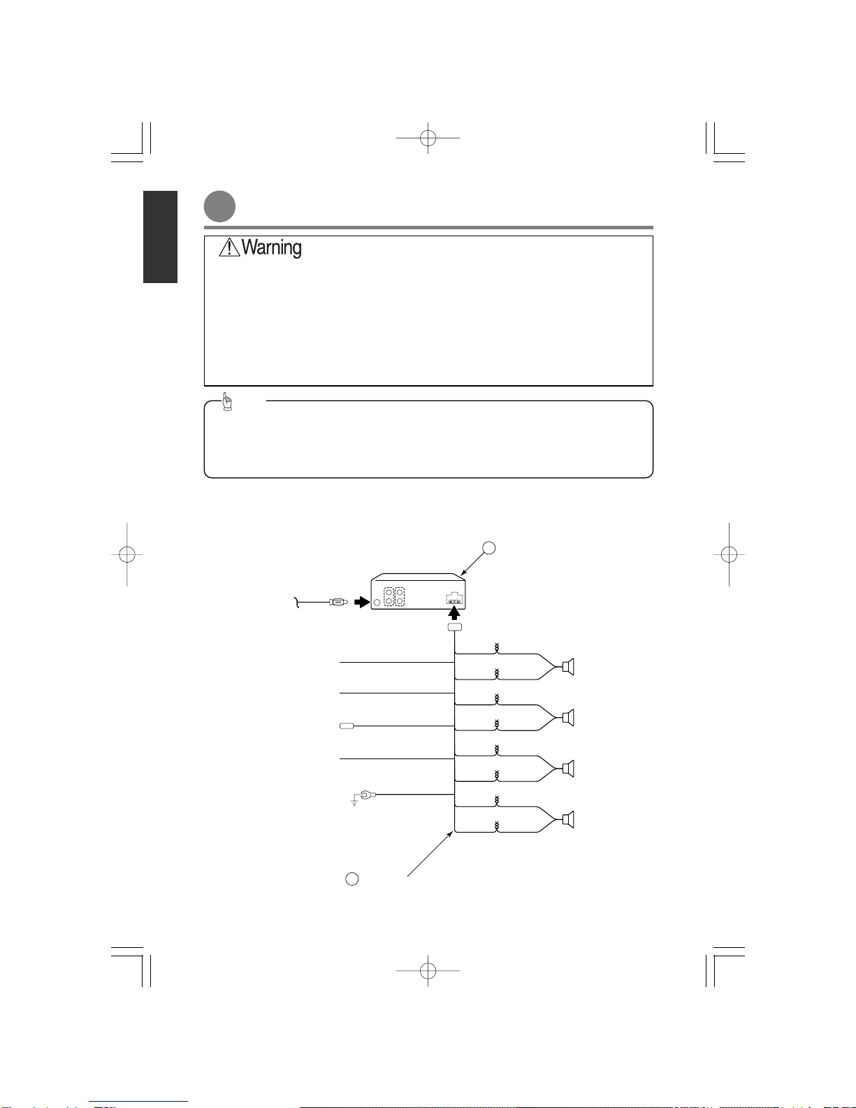
••Never supply power to another electrical appliance
by splicing or tapping into this main unit's power wire.
Otherwise, the current capacity of the wire will be
exceeded, resulting in a fire or electric shock.
••Never attempt to disassemble or modify the main
unit. Otherwise, an accident, fire, or electric shock
may result.
••When installing the main unit into a vehicle with a
passenger side air bag, do not secure it to the air
bag's cover or in places where it may impede air bag
deployment. Otherwise, proper air bag operation may
not be ensured in the event of an accident, causing
injury or death.
••When making holes (example: drilling) be sure to
wear protective eyewear. Otherwise, an injury such
as loss of eyesight may result.
••Exposed wires must be insulated with electrical tape.
Otherwise, a short circuit, fire, or electric shock may
result.
••Do not modify this system for use other than that
specified herein. Also, do not deviate from the
installation procedures described herein; Eclipse will
not be held liable for damages including, but not
limited to serious injury, death, or property damage
resulting from installations that enable unintended
operation.
••This main unit is intended for operation in DC 12volt,
negative-grounded vehicles only. Never use it in 24-
volt vehicles such as heavy trucks or diesel vehicle
with cold-region specifications.
••Do not install this main unit in locations where it may
obstruct the driver's view, or where it may endanger
passengers in the vehicle. Otherwise, an accident or
injury may result.
••Do not install this main unit in locations where it may
interfere with the operation of the steering wheel,
shift lever, brake pedal, etc. Otherwise, an accident
or injury may result.
••To prevent damage to the vehicle, confirm the
locations of hoses, electrical wiring, and the fuel tank
prior to drilling holes to install this main unit. Also,
take precautions so that the main unit does not
interfere, nor come in contact with them. Otherwise,
a fire may result.
••When installing this main unit, never use the existing
nuts or bolts that secure parts of the fuel tank, or the
steering, or braking systems. Otherwise, improper
steering, or braking or a fire may result.
••To prevent a short circuit from occurring, disconnect
the battery's negative terminal before installing this
main unit. Otherwise, an electric shock or injury may
result.
••When using an existing nut and/or bolt from the
vehicle to ground this main unit, do not use any that
secure parts of the steering or braking systems.
Otherwise, an accident may result.
••Bundle wires and harnesses with electrical tape or
wire ties to prevent them from interfering with moving
parts. If they should entangle with the steering wheel,
shift lever, or brake pedal, an accident may result.
3-29010CD1000US05.11.295:29PMページ3

-
4
-
English Español Français Italiano
Nederlands
SvenskaEnglish
••This main unit must be operated only as on-board
main unit, or it may cause electrical shock or injury.
••Do not play distorted sounds for long periods of time;
the speakers may overheat and cause a fire.
••Use supplied wire harness with this main unit. Other
manufacturers may use a similar wire harness
connector but pin configurations are incorrect for use
with Eclipse main units and can damage the main
unit. Prior to powering up the main unit, please make
sure the main unit is properly grounded with the
vehicle chassis. If no ground is available to the
chassis, add a ground strap from the main unit to the
vehicle chassis to improve the ground.
••Do not use with speakers having 1 to 3 ohms
impedance. This main unit is designed to be used
with high-powered speakers rated above 50w with
impedance rating between 4 and 8 ohms.
••For best results, this main unit should be installed by
a professional installer.
Contact the dealer whom you purchased the main
unit for an appointment.
••When installing this main unit, be sure to use the
supplied mounting hardware. If parts other than
those supplied are used, the main unit may be
damaged internally, or may not be held in place
securely and become dislodged.
••Avoid installing this main unit in places where it may
get wet, such as near windows, or in places that are
moist or dusty. Presence of liquid, moisture, or dust
inside this main unit can cause short circuiting
resulting in smoke or fire.
••If this main unit is not connected properly, a short
circuit, fire, or accident may occur.
••When routing wires, use precautions to prevent
contact of sharp metal parts such as brackets or
screw tips. Otherwise, a short circuit, electric shock,
fire, or accident may result.
••Play the audio at a moderate volume level that
permits you to hear sounds from outside the vehicle.
Driving without being able to hear outside sounds
may result in an accident.
••Do not operate the main unit in a malfunctioning
condition, for instance, when the audio does not play.
Doing so may result in an accident, fire, or electrical
shock.
••If an abnormal situation occurs, such as foreign
matter entering or liquid splashing on the main unit,
or smoke or a strange odor emitting from the main
unit, shut off the main unit immediately and consult
the dealer from whom you purchased it. Continued
operation may cause an accident, fire, or electrical
shock.
••Do not place the vinyl storage bag over a person's
head. It may cause a serious accident or death by
suffocation.
••Do not disassemble or rebuild this main unit. Doing
so may cause an accident, fire, or electrical shock.
••When it is necessary to replace the fuse, always use
a fuse of the correct rating (number of amperes). Use
of fuses with higher amperage ratings may cause a
fire.
3-29010CD1000US05.11.295:29PMページ4

1
3
4
6
16P
5
B
ANTENNA PLUG
MAIN UNIT
1
INTERCONNECTING WIRES
(Power and speaker connector)
2
A
-
5
-
Name and functions of ter
Name and functions of terminals
minals
2
Español Français Italiano
Nederlands
SvenskaEnglish
••Refer to page 6 for details on the wire colors and connection points for interconnecting wires .
••Refer to page 6 for details on connection points and for the main unit wires and
terminals.
2
Tip
7
15A FUSE
A B
••Never cut the insulation on the power wire or use it to power any other equipment. If the rated current
capacity of the power wire is exceeded, fire and electric shocks may result.
••The wires should be secured with tape or a similar securing method to prevent any obstructions while
driving. If they get wound or entangled around components such as the steering wheel, shifting lever,
or brake pedal, accidents may result.
••If removing the end of the wire to connect to another wire, be sure to wrap PVC tape or a similar wire
insulating method around the connection to insulate it. If the connection is not insulated, fire or
accidents may result.
••Use supplied wire harness with this main unit. Other manufacturers may use a similar wire harness
connector but pin configurations are incorrect for use with Eclipse main units and can damage the main
unit. Prior to powering up the main unit, please make sure the main unit is properly grounded with the
vehicle chassis. If no ground is available to the chassis, add a ground strap from the main unit to the
vehicle chassis to improve the ground.
••Do not use with speakers having 1 to 3 ohms impedance. This main unit is designed to be used with
high-powered speakers rated above 50w with impedance rating between 4 and 8 ohms.
3-29010CD1000US05.11.295:29PMページ5

-
6
-
Wire colors and connection points for connection wires
2
Never connect the power supply to the speaker wires (No.5 and No.6),
otherwise it will cause damage to the main unit.
Caution
ACC (Red)
Connect where the power comes on when the ignition is in the ACC position.
B+ (Yellow)
Connect where power is constantly available, regardless of the ignition key's position.
Ground (Black)
Connect where good body grounding is available.
Control power supply or automatic antenna power supply connection terminal (blue/white)
Connect to the power supply terminal for the power amplifier or other equipment, or to the vehicle’s automatic
antenna control terminal. (200mA max.)
Front speaker output wires
Connect to the front speakers. White: Left + White/black: Left -
Gray: Right + Gray/Black: Right -
Rear speaker output wires
Connect to the rear speakers. Green: Left + Green/black: Left -
Purple: Right + Purple/Black: Right -
Cellular phone mute Wire (Pink)
Connect to the ground output terminal on a mobile phone.
7
6
5
4
3
2
1
English Español Français Italiano
Nederlands
SvenskaEnglish
Main unit connections
Front line-out terminals
Connect to the RCA connector of an external amplifier.
Rear line-out terminals
Connect to the RCA connector of an external amplifier.
A
B
3-29010CD1000US05.11.295:29PMページ6

-
7
-
Español Français Italiano
Nederlands
SvenskaEnglish
Vehicle component adapter wires
Vehicle harness
From main unit
-
Example of using vehicle adapter wires
-
-
Vehicle connections
-
••You will need to purchase the necessary vehicle component adapter wire for the vehicle so that the
power supplies can be utilized. (Contact the dealer for further details.)
••Be sure to wrap the connection wires with electrical tape or another insulation method to insulate them.
Tip
Power supplies
for combined
equipment
3-29010CD1000US05.11.295:29PMページ7

-
8
-
English Español Français Italiano
Nederlands
SvenskaEnglish
System connection e
System connection example
xample
REAR SPEAKERS
FRONT SPEAKERS
TO GROUND
TO ACC (Power Supply)
Red
TO TURN-ON WIRE OF EXTERNAL EQIPMENT
(Supply)
OR
TO POWER ANTENNA RELAY (Supply)
Blue/White
TO BATTERY+12V (Permanent Supply)
Yellow
Black
16P
MAIN UNIT
1
INTERCONNECTING WIRES
(Power and speaker connector)
2
White
White/Black
Gray
Green
Green/Black
Purple
Purple/Black
TEL MUTE
Pink
ANTENNA PLUG
■CD1000 Main unit, used alone
••Never cut the insulation on the power wire or use it to power any other equipment. If the rated current
capacity of the power wire is exceeded, fire and electric shocks may result.
••The wires should be secured with tape or a similar securing method to prevent any obstructions while
driving. If they get wound or entangled around components such as the steering wheel, shifting lever,
or brake pedal, accidents may result.
••If removing the end of the wire to connect to another wire, be sure to wrap PVC tape or a similar wire
insulating method around the connection to insulate it. If the connection is not insulated, fire or
accidents may result.
••Install and connect all of the peripheral equipment before connecting them to the main unit.
••Do not remove any of the protective caps (RCA, etc.) unless in use.
••Be sure to wrap the connection wires with tape (PVC tape) to insulate them.
••Adjust the external amplifier’s input level.
Tip
Gray/Black
3-29010CD1000US05.11.295:29PMページ8

-
9
-
Installing the main unit
Español Français Italiano
Nederlands
SvenskaEnglish
30˚ or less
Level (reference)
Front
-
Installation angle
-
To maintain proper function, the main unit must be
mounted less than 30 degrees. If the angle is in
excess of 30 degrees, CD skipping and improper
CD ejection may occur.
Tip
Remove the bezel.
1
When it is not required to detach the front control
panel from the main unit, use the provided screw
to attach the control panel to the main unit.
Tip
-
Installation preparation
-
Mounting sleeve
3
Bezel
5
2Insert the audio unit removal tool on the left and
right side of the main unit, and disengage the lock
of the mounting sleeve.
Be careful not to damage the fuse that is installed
on the back side of the main unit when removing
the mounting sleeve from the main unit.
Tip
Main unit
1
3Remove the mounting sleeve from the main unit.
Main unit
1
Mounting sleeve
3
Mounting sleeve
3
Mounting sleeve
3
Screw
13
15A fuse
Detachable panel
3-29010CD1000US05.11.295:29PMページ9

-
10
-
English Español Français Italiano
Nederlands
SvenskaEnglish
6
5
4
Install the bezel on the main unit.
Fasten the rear of the main unit.
Insert the main unit into the mounting sleeve until
it locks in place.
Bezel
5Bushing
9
Metal of vehicle
Stud bolt
8
Mount the stud bolt and bushing to the main unit.
3
••Be careful not to forcefully push on the main unit's
display or buttons during installation. This may
result in damage to the main unit.
••This installation method is only one example.
When installing the main unit to the vehicle, be
sure to ask the place of purchase for information
on the installation method used.
Tip
••Carefully bind any excess length of wire that is connected to the main unit and secure it to an area of
empty space in the vehicle so that it does not dislodge or interfere with the main unit or vehicle-side
equipment. If the wires are not handled correctly, operating problems or short-circuits may occur, and
this may result in the danger of fire or other accidents.
••Connect all wires before installing the main unit.
Tip
Insert the mounting sleeve into the opening in the
vehicle dashboard or console box.
1
Use a screwdriver or a similar tool to bend the
tabs in the mounting sleeve to secure the
mounting sleeve.
2
Bend the mounting
tabs.
Dashboard or
console box
Mounting sleeve
3
-
Removing the main unit (If installing the main unit using the mounting sleeve)
-
Mounting sleeve
3
Bezel
5
-
Mounting the main unit (If installing the main unit using the mounting sleeve)
-
Remove the detachable panel.
1
Remove the bezel.
2
3Insert the audio unit removal tool on the left and
right side of main unit, and disengage the lock of
the mounting sleeve.
4Remove the main unit from the mounting sleeve.
Dashboard or console box
Main unit
1
Main unit
1
Dashboard or
console box
Detachable panel
Detachable panel
3-29010CD1000US05.11.295:29PMページ10

-
11
-
Attach the brackets to the main unit.
3
Install the main unit in the vehicle.
4
Main unit
Pocket
Round-head bolt
(Red:M5 x 8) x 4
Screw
x 4
Select the screws in accordance with the shapes
of the screw holes in the mounting bracket.
6
1
Mounting bracket
Round-head bolt
(Red:M5 x 8) x 4
Flat head
screw
(
Red:
M5x8) x 4
67
Be sure to use the supplied accessory mounting
screws (Red:M5 x 8) as the mounting screws. If
any other screws are used, they may damage the
inside of the main unit.
Tip
••Be careful not to forcefully push on the main unit's
display or buttons during installation. This may
result in damage to the main unit.
••This installation method is only one example.
When installing the main unit to the vehicle, be
sure to ask the place of purchase for information
on the installation method used.
Tip
Remove the pocket and any other accessories
from the center cluster to make room for the main
unit.
1
Remove the mounting brackets for the pocket.
2
Mounting bolts
Pocket, etc
Center cluster panel
-
Mounting the main unit (If installing the main unit using the side brackets of the vehicle)
-
••Carefully bind any excess length of wire that
is connected to the main unit and secure it
to an area of empty space in the vehicle so
that it does not dislodge or interfere with the
main unit or vehicle-side equipment. If the
wires are not handled correctly, operating
problems or short-circuits may occur, and
this may result in the danger of fire or other
accidents.
••Connect all wires before installing the main
unit.
Tip
Español Français Italiano
Nederlands
SvenskaEnglish
3-29010CD1000US05.11.295:29PMページ11

-
12
-
English Español Français Italiano
Nederlands
SvenskaEnglish
3-29010CD1000US05.11.295:29PMページ12

Deutsch Español Français Italiano
Nederlands
SvenskaEspañol
MODELO
Asegúrese de leer completamente este manual de instalación antes de llevar a cabo la instalación y
realizar conexiones. Si se utilizan métodos de instalación o piezas no estándares que no se detallan en
este manual podrían producirse accidentes o lesiones.
Se recomienda una instalación profesional, comuníquese con el lugar donde realizó la compra para
programar una cita.
Después de leer completamente el manual del propietario y el manual de instalación, guárdelos en un
lugar seguro para referencia futura.
Para los comerciantes:
Entregue el manual de instalación al cliente después de terminar con la instalación y todas las
conexiones.
Contenido
Contenido
Componentes 2
Antes de la
instalación
Instalación
Conexiones
Para su seguridad al utilizar el CD1000 3
Nombres y funciones de las terminales 5
Cómo instalar la unidad principal 9
MANUAL DE INSTALACIÓN
Ejemplo de conexión del sistema 7
Deutsch Español Français Italiano
Nederlands
SvenskaEspañol
CD Multi-Source Receiver
3-29010CD1000MX05.11.295:39PMページ1

-
2
-
Deutsch Español Français Italiano
Nederlands
SvenskaEspañol
Componentes
Componentes
Verifique que no falte ninguno de los siguientes componentes
Al momento de instalar la unidad principal, algunos modelos de vehículos pueden requerir el uso de
artículos que deben obtenerse por separado como por ejemplo un cable adaptador para la fuente de
alimentación, cable adaptador de la antena de radio o soporte de montaje.
Consejo
Deutsch Español Français Italiano
Nederlands
SvenskaEspañol
Unidad principal
x 1
1
Cable de interconexión
(Conector de energía y parlante)
(16P) x 1
2
Acoplador de montaje
x 1
3
Herramienta para extraer
la unidad de audio
x 2
4
Tapa
x 1
5
Perno de cabeza redonda
(Rojo:M5x8) x 4
6
Tornillo de cabeza plana
(Rojo:M5x8) x 4
7
Tornillo opresor
x 1
8
Codo doble
x 1
9
Tuerca hexagonal
(M5)
x 1
11
Estuche
(Para panel desmontable) x 1
10
Arandela
(M5)
x 1
12
tornillo
(M2x6) x 1
13
3-29010CD1000MX05.11.295:39PMページ2

-
3
-
Deutsch Español Français Italiano
Nederlands
SvenskaEspañol
En todo el manual y en el CD1000 aparecen señales de advertencia y precaución como las que se
ejemplifican a continuación. Éstas muestran las formas seguras y correctas de manejar el producto para
prevenir que usted y otros sufran lesiones personales y evitar daños a la propiedad.
Antes de leer el manual, tómese el tiempo para leer y aprender la importante información enumerada en
esta sección.
Esta señal de “Advertencia” indica una situación en la que el manejo
incorrecto puede ocasionar la muerte o lesiones corporales serias.
Esta señal de “Precaución” indica una situación en la que el manejo
incorrecto puede ocasionar lesiones corporales o únicamente daños a la
propiedad.
P
Par
ara su segur
a su seguridad al utilizar el
idad al utilizar el CD1000
CD1000
Esta sección contiene información que puede ayudarlo a prevenir
problemas y daños en la unidad y también contiene otra información útil.
Consejo
Advertencia
Precaución
Deutsch Español Français Italiano
Nederlands
SvenskaEspañol
••Nunca suministre energía a otro dispositivo eléctrico
uniéndolo o conectándolo a la línea de alimentación
(cable) de este producto. De lo contrario, se
excederá la capacidad actual del cable, lo que
ocasionará un incendio o descarga eléctrica.
••Nunca intente desarmar ni modificar el producto.
De lo contrario, podría producirse un accidente,
incendio o una descarga eléctrica.
••Cuando instale el producto en un vehículo con bolsa
de aire en el asiento del pasajero, no lo asegure a la
tapa de la bolsa de aire o en lugares donde pueda
impedir el despliegue de la bolsa de aire. De lo
contrario, no se podrá garantizar el correcto
funcionamiento de la bolsa de aire en caso de un
accidente, lo que causará lesiones o la muerte.
••Al hacer agujeros (por ejemplo: perforaciones)
asegúrese de utilizar protectores de ojos. De lo
contrario, podría producirse una lesión como la
pérdida de la vista.
••Los cables expuestos deben aislarse con cinta
aislante.
De lo contrario, podría producirse un corto circuito,
incendio o una descarga eléctrica.
••No modifique este sistema para otro uso distinto del
que aquí se detalla. Tampoco se desvíe de los
procedimientos de instalación aquí descritos.
Eclipse no se hará responsable por daños, los que
incluyen, pero no se limitan a, lesiones graves,
muerte o daños a la propiedad debido a
instalaciones que ocasionan un funcionamiento no
intencionado.
••Esta unidad está pensada para funcionar sólo en
vehículos con conexión a tierra negativa de CC de
12 voltios. Nunca la utilice en vehículos de 24 voltios
como camiones de gran tonelaje o automóviles
diesel con especificaciones para regiones frías.
••No instale este producto en lugares donde pueda
obstruir la visión del conductor o donde pueda poner
en peligro a los pasajeros del vehículo. De lo
contrario, podría producirse un accidente o lesiones.
••No instale este producto en lugares donde pueda
interferir con el funcionamiento del volante, la
palanca de cambios, el pedal de freno, etc. De lo
contrario, podría producirse un accidente o lesiones.
••Para prevenir daños en el vehículo, verifique la
ubicación de las mangueras, el cableado eléctrico y
el tanque de combustible antes de perforar agujeros
para instalar este producto. Además, actúe con
precaución para que el producto no interfiera ni esté
en contacto con ellos. De lo contrario, se puede
ocasionar un incendio.
••Cuando instale este producto, nunca utilice las
tuercas ni los pernos que aseguran las partes del
tanque de combustible o los sistemas de dirección o
frenado. De lo contrario, podría producirse el
funcionamiento incorrecto de la dirección o de los
frenos, o un incendio.
••Para prevenir un corto circuito, desconecte la
terminal negativa de la batería antes de instalar este
producto. De lo contrario, podría producirse una
descarga eléctrica o lesiones.
••Cuando utilice una tuerca y/o perno existente en el
vehículo para conectar a tierra este producto, no
utilice ninguno que asegure partes de los sistemas
de dirección o frenado.
De lo contrario, podría producirse un accidente.
••Ate los cables y arneses con cinta aislante o sujeta
cables para evitar que interfieran con partes en
movimiento. Si se enredaran con el volante, la
palanca de cambios o el pedal de frenos, podría
producirse un accidente.
Advertencia
3-29010CD1000MX05.11.295:39PMページ3

-
4
-
Deutsch Español Français Italiano
Nederlands
SvenskaEspañolDeutsch Español Français Italiano
Nederlands
SvenskaEspañol
••Se debe operar este producto sólo como un equipo a
bordo o puede producir descargas eléctricas o
lesiones.
••No reproduzca sonidos distorsionados por largos
períodos; los parlantes podrían sobrecalentarse y
causar un incendio.
••Utilice el arnés de cables suministrado con la unidad.
Otros fabricantes pueden utilizar un conector del
arnés de cables similar pero las configuraciones de
las clavijas no son las correctas para utilizar con los
productos Eclipse y puede dañar las unidades.
Antes de encender la unidad, asegúrese de que esté
conectada a tierra correctamente con el chasis del
vehículo. Si no está disponible la conexión a tierra
del chasis, agregue una correa de conexión a tierra
desde la unidad al chasis del vehículo para mejorar
la conexión a tierra.
••No la utilice con los parlantes que tienen una
impedancia de 1 a 3 ohmios. Esta unidad está
diseñada para utilizarse con parlantes de alta
potencia superior a 50w, con una impedancia de
entre 4 y 8 ohmios.
••Para obtener mejores resultados, un instalador
profesional debería instalar este producto.
Comuníquese con el comerciante al que le compró el
producto para programar una cita.
••Cuando instale este producto, asegúrese de utilizar el
equipamiento de montaje incluido. Si se utilizan otras
partes distintas de las incluidas, la unidad podría
dañarse internamente o podría no quedar bien sujeta
y desplazarse.
••Evite instalar este producto en lugares donde pueda
mojarse, como cerca de ventanas o en lugares que
están húmedos o llenos de polvo. La presencia de
líquidos, humedad o polvo dentro de este producto
puede producir un corto circuito que origine humo o
incendio.
••Si no se conecta correctamente este producto, podría
producirse un corto circuito, incendio o accidente.
••Cuando guíe los cables, actúe con precaución para
evitar el contacto de partes filosas de metal como
abrazaderas o puntas de tornillos. De lo contrario,
podría producirse un corto circuito, descarga
eléctrica, incendio o accidente.
••Reproduzca el audio en un nivel moderado de
volumen que le permita escuchar los sonidos fuera
del automóvil.
Conducir sin poder escuchar los sonidos exteriores
puede causar un accidente.
••Si se produjera una situación anormal, como el
ingreso de un material extraño o salpicadura de
líquido en el producto, o humo u olor que sale de la
unidad, apague el producto inmediatamente y
comuníquese con el comerciante al que se lo
compró. Continuar con el funcionamiento podría
producir un accidente, incendio o descarga eléctrica.
••No coloque la bolsa de almacenamiento de vinilo
sobre la cabeza de una persona. Podría producir un
serio accidente o muerte por asfixia.
••No desarme ni reconstruya este producto. Hacer
esto podría producir un accidente, incendio o
descarga eléctrica.
••Cuando sea necesario reemplazar el fusible, siempre
utilice un fusible con la clasificación correcta (número
de amperes). El uso de fusibles con un amperaje
mayor podría provocar un incendio.
••No haga funcionar el producto si está en malas
condiciones, por ejemplo, cuando el audio no
funciona.
Hacer esto podría producir un accidente, incendio o
descarga eléctrica.
Advertencia
Precaución
3-29010CD1000MX05.11.295:39PMページ4

-
5
-
Deutsch Español Français Italiano
Nederlands
SvenskaEspañol Français Italiano
Nederlands
Svenska
••Nunca corte el aislante en el cable de alimentación ni lo utilice para accionar otro equipo. Si se excede
la capacidad nominal de corriente del cable de alimentación, podría producirse un incendio o
descargas eléctricas.
••Se deben asegurar los cables con cinta o algún método de seguridad similar para evitar obstrucciones
mientras maneja. Si se dañan o enredan cerca de componentes como el volante, palanca de cambios
o pedal de freno, podrían producirse accidentes.
••Si quita el extremo del cable para conectar a otro cable, asegúrese de enrollar cinta de PVC o un
método aislante de cables similar alrededor de la conexión para aislarla. Si no se aísla la conexión, se
podría producir un incendio o accidentes.
Nombres y funciones de las ter
Nombres y funciones de las terminales
minales
Advertencia
••Utilice el arnés de cables suministrado con la unidad. Otros fabricantes pueden utilizar un conector del
arnés de cables similar pero las configuraciones de las clavijas no son las correctas para utilizar con
los productos Eclipse y puede dañar las unidades. Antes de encender la unidad, asegúrese de que
esté conectada a tierra correctamente con el chasis del vehículo. Si no está disponible la conexión a
tierra del chasis, agregue una correa de conexión a tierra desde la unidad al chasis del vehículo para
mejorar la conexión a tierra.
••No la utilice con los parlantes que tienen una impedancia de 1 a 3 ohmios. Esta unidad está diseñada
para utilizarse con parlantes de alta potencia superior a 50w, con una impedancia de entre 4 y 8
ohmios.
Precaución
Deutsch EspañolEspañol
••Consulte la página 6 para detalles sobre los colores de los cables y los puntos de conexión para los
cables de interconexión .
••Consulte la página 6 para detalles sobre los puntos de conexión y para los cables y
terminales de la unidad principal.
2
Consejo
AB
1
3
4
6
5
B
A
2
7
16P
ENCHUFE DE LA ANTENA
UNIDAD PRINCIPAL
1
2CABLE DE INTERCONEXIÓN
(Conector de energía y parlante)
FUSIBLE 15A
3-29010CD1000MX05.11.295:39PMページ5

-
6
-
Deutsch Español Français Italiano
Nederlands
SvenskaEspañol
ACC (Rojo)
Conecte donde haya energía cuando la llave de encendido esté en la posición ACC.
B+ (Amarillo)
Conecte donde haya energía constantemente, sin importar la posición de la llave de encendido.
Conexión a tierra (Negro)
Conéctelo donde haya buena conexión a tierra con el chasis.
Terminal de conexión del suministro de energía de control o del suministro de energía
automático de la antena (azul/blanco)
Conecte al terminal del suministro de energía para el amplificador de potencia u otra unidad, o al terminal de
control automático de la antena del vehículo. (max. 200mA )
Conductor de salida del parlante delantero
Conéctelo a los parlantes delanteros. Blanco: Izquierda + Blanco/Negro: Izquierda -
Gris: Derecha + Gris/Negro: Derecha –
Conductor de salida del parlante trasero
Conéctelo a los parlantes traseros. Verde: Izquierda + Verde/Negro: Izquierda -
Púrpura: Derecha +
Púrpura/Negro: Derecha –
Cable apagado para el teléfono celular (Rosado)
Conectar al terminal de salida con conexión a tierra en un teléfono celular.
7
6
5
4
3
1
Colores de los cables y puntos de conexión para los cables de conexión
2
Nunca conecte la fuente de alimentación en las tomas de conexión del parlante (No. 5 y No.
6); de lo contrario dañará la unidad principal.
Caution
2
Precaución
Deutsch Español Français Italiano
Nederlands
SvenskaEspañol
Terminal de salida de línea frontal
Conéctelo al conector RCA de un amplificador externo.
Terminal de salida de línea trasera
Conéctelo al conector RCA de un amplificador externo.
A
Conexiones de la unidad principal
B
3-29010CD1000MX05.11.295:39PMページ6

-
7
-
Deutsch Español Français Italiano
Nederlands
SvenskaEspañol
Français Italiano
Nederlands
SvenskaDeutsch EspañolEspañol
Italiano
Nederlands
Svenska
-
Ejemplo de cómo utilizar los cables adaptadores para el vehículo
-
-
Conexiones del vehículo
-
••Deberá comprar el cable adaptador del componente necesario para el vehículo para poder utilizar las
fuentes de alimentación. (Comuníquese con el comerciante para obtener más información.)
••Asegúrese de envolver los cables de conexión con cinta aislante o cualquier otro método aislante para
aislarlos.
Consejo
Deutsch Español FrançaisEspañol
Cable adaptador del componente para el vehículo
Arnés del vehículo
De la unidad principal
Fuentes de
alimentación para
productos
combinados
3-29010CD1000MX05.11.295:39PMページ7

-
8
-
Deutsch Español Français Italiano
Nederlands
SvenskaEspañol
Ejemplo de cone
Ejemplo de conexión del sistema
xión del sistema
••Nunca corte el aislante en el cable de alimentación ni lo utilice para accionar otro equipo. Si se excede
la capacidad nominal de corriente del cable de alimentación, podría producirse un incendio o
descargas eléctricas.
••Se deben asegurar los cables con cinta o algún método de seguridad similar para evitar obstrucciones
mientras maneja. Si se dañan o enredan cerca de componentes como el volante, palanca de cambios
o pedal de freno, podrían producirse accidentes.
••Si quita el extremo del cable para conectar a otro cable, asegúrese de enrollar cinta de PVC o un
método aislante de cables similar alrededor de la conexión para aislarla. Si no se aísla la conexión, se
podría producir un incendio o accidentes.
••Instale y conecte todas las unidades periféricas antes de conectarlas a la unidad principal.
••No quite ninguno de los tapones protectores (RCA, etc.) a menos que estén en uso.
••Asegúrese de enrollar los cables de conexión con cinta (cinta de PVC) para aislarlos.
••Ajuste el nivel de entrada del amplificador externo.
Consejo
■CD1000 Unidad principal, se utiliza por separado
PARLANTES TRASEROS
PARLANTES DELANTEROS
HACIA CONEXIÓN A TIERRA
HACIA ACC(Fuente de alimentación)
Rojo
Azul/Blanco
HACIA LA BATERÍA + 12V(Suministro permanente) Amarillo
Negro
16P
ENCHUFE DE LA ANTENA
Unidad principal
1
Cable de interconexión
(Conector de energía y parlante)
2
Blanco
Blanco/Negro
Gris
Gris/Negro
Verde
Verde/Negro
Púrpura
Púrpura/Negro
HACIA EL CONDUCTOR DEL ENCENDIDO DEL
EQUIPO EXTERNO (Suministro)
HACIA EL RELÉ DE LA ANTENA ELÉCTRICA
(SUMINISTRO)
TEL APAGADO Rosado
3-29010CD1000MX05.11.295:39PMページ8
Other manuals for Eclipse CD 1000
1
Table of contents
Languages:
Other Fujitsu Car Receiver manuals