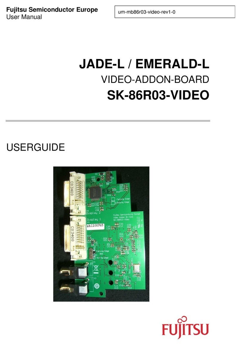
Fujitsu MB86R02 User manual

MB86R02 ‘Jade-D’ Hardware Manual V1.64
MB86R02 ‘Jade-D’
Graphics Controller
Hardware Manual
Fujitsu Semiconductor Europe GmbH
Release 1.64 (amended)
(17.09.2013 13:11)
This document is subject to changes
and corrections without prior warning

MB86R02 ‘Jade-D’ Hardware Manual V1.64
Preface
Intention and Target Audience of this Document
This document describes and gives you detailed insight to the stated Fujitsu semiconductor product.
The MB86R02 ‘Jade-D’ device is the successor of Fujitsu’s MB86R01 ‘Jade’ and contains both
improvements and many new features.
This target audience of this document is engineers developing products which will use the MB86R02
‘Jade-D’ device. It describes the function and operation of the device. Please read this document
carefully.
Trademarks
APIX is a registered trademark of Inova Semiconductors GmbH, Grafinger Str. 26, 81671
Munich, Germany.
ARM is a registered trademark of ARM Limited in UK, USA and Taiwan.
ARM is a trademark of ARM Limited in Japan and Korea.
ARM Powered logo is a registered trademark of ARM Limited in Japan, UK, USA, and Taiwan.
ARM Powered logo is a trademark of ARM Limited in Korea.
ARM926EJ-S and ETM9 are trademarks of ARM Limited.
System names and the product names which appear in this document are the trademarks of the
respective company or organization.
Licenses
Under the conditions of Philips corporation I2C patent, the license is valid where the device is used in
an I2C system which conforms to the I2C standard specification by Philips Corporation.
The purchase of Fujitsu I2C components conveys a license under the Philips I2C Patent Rights to
use these components in an I2C system, provided that the system conforms to the I2C Standard
Specification as defined by Philips.

MB86R02 ‘Jade-D’ Hardware Manual V1.64
The contents of this document are subject to change without notice. Customers are advised to
consult with FUJITSU sales representatives before ordering.
Any information in this document, including functional descriptions and schematic diagrams, shall not
be construed as license of the use or the exercising of any intellectual property rights, such as patent
rights or copyright or any other right of FUJITSU or any third party or does FUJITSU warrant non-
infringement of any third-party's intellectual property right or other right by using such information.
FUJITSU assumes no liability for any infringement of the intellectual property rights or other rights of
third parties which would result from the use of information contained herein.
The products described in this document are designed, developed and manufactured for general use,
including unrestricted ordinary industrial use, general office use, personal use, and household use but
are not designed, developed and manufactured for use accompanying fatal risks or dangers that,
unless extremely high safety levels are ensured, could have a serious effect to the public and could
lead directly to death, personal injury, severe physical damage or other loss (i.e., nuclear reaction
control in nuclear facility, aircraft flight control, air traffic control, mass transport control, medical life
support system, missile launch control in weapon systems), or (2) for use requiring extremely high
reliability (i.e., submarine or satellite technology). Please note that FUJITSU will not be liable against
you and/or any third party for any claims or damages arising in connection with above-mentioned
uses of the products.
If any products described in this document represent goods or technologies subject to certain
restrictions on export under the Foreign Exchange and Foreign Trade Law of Japan, the prior
authorization by the Japanese government will be required for export of those products from Japan.
All rights reserved and Copyright © FUJITSU SEMICONDUCTOR EUROPE 2010

MB86R02 ‘Jade-D’ Hardware Manual V1.64
Document Change History
Version
Date
Editor
Comment
V1.64 (amended)
17.09.2013
RvReitzenstein
Table ‘Pin Functional Description’ rectified.
Amended row are marked with a change bar on the right side.
Amended entries are marked bold.
V1.64
30.01.2013
von Treuberg
Extended section 17.2.1.3 '
Jade-D Restrictions'.
Removed reference to Application note on APIX jitter (no
longer applies). Added hint on using Demand Mode for
DMA/UART transfers.
V1.63
30.01.2012
von Treuberg
Changed RSDS electrical characteristics.
V1.62
07.11.2011
von Treuberg
Changed Channel Mapping table (26.6).
V1.61 21.09.2011 von Treuberg Corrected pin names in chapters 1, 7, 17:
APIX_n_SB > APIXn_SB_
APIX_SB0 > APIX0_SB
APIX_SB1 > APIX1_SB
APIX_SB5-0 > APIX0_SB
APIX1_SB5-0 > APIX1_SB
Modified section 5.1.13 (Only ES2 > Not available in ES1)
Extended Driving capability 2: list in 34.4.1, 3.3V Standard
CMOS I/O.
RLD: Changed statement 'little endian' to 'big endian'.
Removed 'Uplink' in description of CH0CFG/CH1CFG bits 6:3.
The swing setting has an effect regardless of RX/TX usage.
Corrected GPIO listings (number of GPIOs effected) with
concern to CMPX_MODE_10 descriptions in mulitplex
overview and register description.
Added an additional note concerning multiplex mode #3 if the
pins are unused (check the table for multiplex mode #3).
Corrected 9.6.1: address of instruction vector table to
0000_0080H.
Corrected IRQ connections diagram in chapter 9. IRQ5 is
connected to IRC2.
Added information about unused case for TRACEDATA_X
pins in pinmultiplex mode #3.
Replaced MediaLB Signal Timings chapter.
V1.60
29.10.2010
von Treuberg
Added new section in Electrical Characteristics: 'Transmitter
Serial Data Signal Characteristics'
V1.50
25.03.2010
von Treuberg
SSCG: Modified modulation peak values (e.g. 3% > 2x 1.56%),
added SSCG settings table for recommended value of 20 kHz.
CRG: Modified table 5-1 Clock Overview List
Electrical Characteristics: Added important requirement for
APIX PLL stability (power-on procedure)
EXTBUS: 11.6.1 corrected typo in description for NOR flash
page access mode.
CNT: Corrected reset values of register CAXI_PS and
CMUX_MD.
EXTBUS: modified diagram in section 11.8 (Word write access
to 16 bit width SRAM/NOR Flash)
I2S: corrected FIFO size from previously documented 18/36

MB86R02 ‘Jade-D’ Hardware Manual V1.64
Words, to the implemented size of 66/132 Words.
CCNT: Modified CCID register fields.
Electrical Characteristics: changes:
(1) Table 34-1 Maximum Ratings
(2) Table 34-3 3.3V Standard CMOS I/O Recommended
Operating Conditions, added driving capabilities.
(3) New section: APIX Characteristics
(4) Added RSDS characteristics
GDC: 18.6.3.3 Direct Color (24 bits/pixel) – corrected RGBA
table (A field is only 1 bit)
GDC: Extended all LxEC descriptions for RGBA (e.g. L1EC,
L2EC etc.)
RLD: byte alignment information added to StrideCfg1 register.
Limitations information added to AHBMTransferWidth Setup
section.
V1.40
19.10.2009
von Treuberg
Overview: Unused pins - changed handling of OSC_FILTER,
changed handling of XTRST pin.
GPIO: re-inserted block diagram (mistakenly removed)
IRC: removed IRQs as only required for debugging
DMAC: Corrected line to MPX_MODE_1[1:0] = "HL" in section
'Related Pins'. Corrected DMA configuration A register
(DMACAx), BC[3:0] and TC[15:0] function descriptions.
RLD: added more detail to DestAddress register description
Electrical characteristics, almost all tables modified
CRG: corrected initial value of CRAM register.
TCON: exchanged Figure 22-4 Block diagram of TSIG.
SSCG: updated register description
UART: changed table 28-2:
(external input condition: CLK = 25.0MHz, CRIPM[3:0] = 0001)
Addendum (differences ES1/ES2): added note about APIX TX
initialization
V1.30
24.07.2009
von Treuberg
CCNT: Corrected typo in description of register CAXI_PS
ADDENDUM: Added note about JTAGSEL polarity
DMAC: changed hex value in second diagram of section
'15.8.1 DMA start in Single channel'
GPIO: corrected base address in table 24-1
DDR2: several small corrections concerning DRIMRx and
OCD adjustment
CCNT: Added note that only 32 bit access to DDR is poss.
when in big endian mode. Extended description of multiplex
mode/function selection register CMUX_MD. Corrected ChipID
register displayed values.
Overview + Addendum: modified MUX tables for better
understanding. Added cell types to pin overview.
Memory map: changed RHlite to APIX, added SSCG area.
Modified Register Access description.
I2C: added 'Example of a slave address transmission'
GPIO: new block diagram and note about configuration of
differential pair configuration in MUX mode 4, function 4
SIG: added limitation for cyclic monitoring mode.
SSCG: added base address to register description.

MB86R02 ‘Jade-D’ Hardware Manual V1.64
CRG: modified description of DPERI register
V1.20
22.06.2009
von Treuberg
CCNT: Page 9-12: corrected typo ADC7 > ADC2
GDC: VCCR register – changed reset value. Corrected table of
DCKD clock delay values and DCM3 description.
APIX: Changed names OscMode, OscBias, OscFilter to
OSC_MODE, OSC_BIAS and OSC_FILTER for consistancy. -
Added upstream channel bandwith limitation
IRC: Added info to IRQ7,8,19,20 ... 23: Unused, corresponding
correction to IRQ table (9.6)
EXTBUS: changed footnote of MCFMODE0/2/4
TCON: Removed superflous section concerning Indigo.
Exchanged block diagram of TSIG (22-4). Modified diagram
'Basic structure of a sync mixer (22-7).
DDR2: corrected flowchart and tables 13-4, 13-6, corrected
13.6.2.2 flow chart and added new explanation text. Added
limitation about read/write when in self-refresh mode.
Corrected 13.7.2.2 OCD Adjustment Procedure, changed
bitfield ODTBIAS in register DROABA.
SSCG: numerous small corrections. Removed references to
1.6 GHz operation (not for Jade-D implementation)
Addendum: added difference in SSCG functional scope
ES1/ES2
DMAC/I2S: added restriction for I2S transfer modes
SIG: Added new example control flow diagram to 21.6.1
Added new chapter 'Electrical Characteristics'
V1.10
18.05.2009
von Treuberg
Overview: corrected bus connection information, added
improved overview of multiplex pin groups, corrected I2S unit
count, added section concerning PU/PD differences ES1/ES2,
updated pin listings/unused pins info
SPI: Added second channel
GDC: corrected display timing table values, added 1280 x 480
GDC: correcrected address offsets of L2WY, L2WW, L2WH
GDC: Modified DCM3 register
GDC: Added DCM1.LCS register description
GDC: Corrected RSDS bitfield initial value (DCM0 register)
CCNT: Renamed register CDEBUG0 > CBSC
CCNT: Renamed register CDEBUG1 > CDCRC
CCNT: Added new register CMSR2
CCNT: Corrected numbers of CMBUS register bitfields
CRG: Minimal register description changes
ADC: Corrected ADC channel mapping table, updated register
description
Added Addendum for differences ES1/ES2
IRC: Added missing registers for IRC2 to overview, corrected
TBR addresses in tables
CLUT: updated diagrams
DITH: updated diagrams
SIG: updated diagrams
TCON: updated diagrams
RLD: updated diagrams
V1.00
12.03.2009
von Treuberg
Overview: Unused pins: changed handling of I2S_ECLK, VPD,

MB86R02 ‘Jade-D’ Hardware Manual V1.64
TDI, added information about internal pull-up/down resistors
for numerous pins, corrected number of IRC channels to 3.
GDC: corrected blending registers description
IRC: Removed IRC overview diagram (covered by tables)
Pin multiplex tables, changes to CMPX_MODE_2[1:0] and
CMPX_MODE_3[1:0] and CMPX_MODE_2[1:0].
V0.05
18.12.2008
von Treuberg
Updated pins lists, package layouts
GDC: initial values of DCM3 register changed
ADC: completely new register description
SSCG: extended and updated register description
PWM: corrected all offset addresses of registers
TCON: updated register description
RBC: added limitation when using VINITHI/REMAP
IRC: replaced TBDs with latest information
DDR2: made changes to 'SDRAM initialization procedure' and
'ODT Setting Procedure'
CCNT: corrected typo in register CIST, added new register
information to CMBUS.
APIX: added application note for PCB designers
V0.04
17.10.2008
von Treuberg
General changes: English improvements
Overview: Added unused pins list
Memory Map (updated figure)
CRG (Table 5-3 timings updated, register descriptions updated
for CRPR, CRHR, CRHB, CSEL, new registers CRDP0.
CRPD1 added)
CCNT (register MBUS2AXU added, changed registers CIST,
CEX_PIN_ST, CMSR1, CMSR2)
APIX (complete register update)
PWM (register update)
V0.03
12.08.2008
von Treuberg
Major changes:
Preface: new block diagram
Overview (preliminary pinning information, multiplexing)
System Configuration (example configuration)
Memory Map (updated figure)
CRG (corrected 42.5 MHz > 41.625 MHz, MLB has 2 clocks,
SELXCLK changed, SSCG register start changed, Hint for
disabling non-active module clocks, predivider reminder
added, added predivider PLL info)
IRC (added IRC2 for 16 new interrupts)
DMAC (added DMA trigger from RH DREQ Rx + Tx)
CCNT (removed USB set and related registers, added soft
reset registers/bitfields, removed IDE related registers,
removed I2S endian bits)
HOSTIFC (content added)
APIX (added content and register description)
PWM (updated register description)
I2S (updated register description)
ADC (extended for 4 channels)
I2C (updated register description)
TCON (Added flow control, revised feature list, added clock
position pin mapping tables, added software reset description,

MB86R02 ‘Jade-D’ Hardware Manual V1.64
app note for RSDS channel order inversion, AC TTL spec
change to 42 MHz)
V0.02 25.05.2007 von Treuberg Reorganization, new chapters, major alterations of
content
V0.01
08.03.2007
von Treuberg
First version

MB86R02 ‘Jade-D’ Hardware Manual V1.64
Table of Contents
1Overview .......................................................................................................................................1-1
1.1 Features .............................................................................................................................1-1
1.2 Block Diagram....................................................................................................................1-3
1.2.1 Outline of each functional block......................................................................................1-4
Function Summary of the Blocks......................................................................................................1-6
1.3 Package Dimensions..........................................................................................................1-9
1.4 Pinning..............................................................................................................................1-10
1.5 Pin Assignment.................................................................................................................1-10
1.5.1 Pin Assignment Table...................................................................................................1-12
1.5.2 Pin Multiplexing.............................................................................................................1-22
1.6 Pin Functional Description................................................................................................1-31
2System Configuration....................................................................................................................2-1
2.1 Typical Application .............................................................................................................2-1
3Memory Map .................................................................................................................................3-1
3.1 Memory Map of LSI............................................................................................................3-1
3.2 Register Access..................................................................................................................3-4
4CPU (ARM926EJ-S core) .............................................................................................................4-1
4.1 Outline of ARM926EJ-S core.............................................................................................4-1
4.2 Features of ARM926EJ-S core ..........................................................................................4-1
4.3 Block diagram of ARM926EJ-S core..................................................................................4-1
4.4 Configuration of ARM926EJ-S and ETM ...........................................................................4-2
5Clock Reset Generator (CRG) ......................................................................................................5-1
5.1 Outline ................................................................................................................................5-1
5.2 Features .............................................................................................................................5-1
5.3 Overview.............................................................................................................................5-2
5.4 Location in the device.........................................................................................................5-3
5.5 Operation............................................................................................................................5-3
5.5.1 Reset Generation............................................................................................................5-3
5.5.2 Clock Generation............................................................................................................5-7
5.6 Registers ..........................................................................................................................5-16
5.1.1. Register list...................................................................................................................5-16
5.1.2. PLL control register (CRPR).........................................................................................5-18
5.1.3. Watchdog timer control register (CRWR).....................................................................5-21
5.1.4. Reset/Standby control register (CRSR)........................................................................5-23
5.1.5. Clock divider control register A (CRDA) .......................................................................5-25
5.1.6. Clock divider control register B (CRDB) .......................................................................5-27
5.1.7. AHB (A) bus clock gate control register (CRHA)..........................................................5-28
5.1.8. APB (A) bus clock gate control register (CRPA) ..........................................................5-29
5.1.9. Reserved control register (CRPB)................................................................................5-30
5.1.10. AHB (B) bus clock gate control register (CRHB) ......................................................5-31
5.1.11. ARM core clock gate control register (CRAM)..........................................................5-32
5.1.12. DPERI clock gate control register (CRDP0, CRDP1) ...............................................5-32
5.1.13. Clock Selector control register (CSEL) .....................................................................5-33
6Spread Spectrum Clock Generator (SSCG) .................................................................................6-1
6.1 Position of Block in whole LSI............................................................................................6-1
6.2 Features .............................................................................................................................6-1
6.2.1 Functional .......................................................................................................................6-1
6.2.2 Limitations.......................................................................................................................6-1

MB86R02 ‘Jade-D’ Hardware Manual V1.64
6.3 Software Interface ..............................................................................................................6-3
6.3.1 Format of Register Description.......................................................................................6-3
6.3.2 Global Address ...............................................................................................................6-4
6.3.3 Register Summary..........................................................................................................6-4
Register Description..........................................................................................................................6-4
6.4 Processing Mode................................................................................................................6-8
6.4.1 Parameter setting for 666MHz PLL clock.......................................................................6-8
6.4.1.1 Parameter setting for SSCG-speed of 15KHz.........................................................6-8
6.4.1.2 Parameter setting for SSCG-speed of 20KHz.........................................................6-9
6.4.1.3 Parameter setting for SSCG-speed of 35KHz.......................................................6-10
6.4.1.4 Parameter setting for SSCG-speed of 50KHz.......................................................6-10
6.5 Control Flow .....................................................................................................................6-11
6.5.1 Operation ......................................................................................................................6-11
7CCNT (Chip Control).....................................................................................................................7-1
7.1 Overview.............................................................................................................................7-1
7.2 Features .............................................................................................................................7-2
7.3 Supply clock .......................................................................................................................7-2
7.4 Registers ............................................................................................................................7-3
7.4.1 Register list.....................................................................................................................7-3
7.4.2 CHIP ID register (CCID) .................................................................................................7-5
7.4.3 Soft reset register (CSRST)............................................................................................7-6
7.4.4 Interrupt status register (CIST).......................................................................................7-7
7.4.5 Interrupt status mask register (CISTM) ..........................................................................7-9
7.4.6 GPIO interrupt status register (CGPIO_IST)................................................................7-11
7.4.7 GPIO interrupt status mask register (CGPIO_ISTM)....................................................7-11
7.4.8 GPIO interrupt polarity setting register (CGPIO_IP).....................................................7-13
7.4.9 GPIO interrupt mode setting register (CGPIO_IM).......................................................7-13
7.4.10 AXI bus wait cycle set register (CAXI_BW)..................................................................7-15
7.4.11 AXI priority setting register (CAXI_PS).........................................................................7-17
7.4.12 Multiplex mode setting register (CMUX_MD) ...............................................................7-19
7.4.13 External pin status register (CEX_PIN_ST)..................................................................7-21
7.4.14 MediaLB set register (CMLB) .......................................................................................7-22
7.4.15 MBUS2AXU set register (CMBUS)...............................................................................7-24
7.4.16 Mode switch register like endian etc. (CBSC) ..............................................................7-25
7.4.17 DDR2 Interface reset control register (CDCRC)...........................................................7-27
7.4.18 Soft reset register 0 for macro (CMSR0)......................................................................7-28
7.4.19 Soft reset register 1 for macro (CMSR1)......................................................................7-30
7.4.20 Soft reset register 2 for macro (CMSR2)......................................................................7-33
8Remap Boot Controller (RBC).......................................................................................................8-1
8.1 Outline ................................................................................................................................8-1
8.2 Features .............................................................................................................................8-1
8.3 Block Diagram....................................................................................................................8-1
8.4 Supply clock .......................................................................................................................8-2
8.5 Register ..............................................................................................................................8-2
8.5.1 Register list.....................................................................................................................8-2
8.5.2 Remap control register (RBREMAP)..............................................................................8-4
8.5.3 VINITHI control register A (RBVIHA)..............................................................................8-5
8.5.4 INITRAM control register A (RBITRA)............................................................................8-6
8.6 Operation............................................................................................................................8-7
8.6.1 RBC reset .......................................................................................................................8-7
8.6.2 Remap control.................................................................................................................8-7
8.6.3 VINITHI control ...............................................................................................................8-7

MB86R02 ‘Jade-D’ Hardware Manual V1.64
8.6.4 INITRAM control .............................................................................................................8-9
9Interrupt Request Controller (IRC)................................................................................................9-1
9.1 Overview.............................................................................................................................9-1
9.2 Features .............................................................................................................................9-1
9.3 Interrupt map......................................................................................................................9-2
9.3.1 Exception vector to ARM926EJ-S core ..........................................................................9-2
9.3.2 Expansion IRQ interrupt vector of IRC0/IRC1................................................................9-3
9.3.3 Interrupt request connection diagram.............................................................................9-6
9.4 Block diagram.....................................................................................................................9-7
9.5 Register ..............................................................................................................................9-8
9.5.1 Register list.....................................................................................................................9-8
9.5.2 IRQ flag register (IRQF)................................................................................................9-15
9.5.3 IRQ mask register (IRQM)............................................................................................9-16
9.5.4 Interrupt level mask register (ILM)................................................................................9-16
9.5.5 ICR monitoring register (ICRMN)..................................................................................9-18
9.5.6 Holding request cancellation level register (HRCL)......................................................9-19
9.5.7 Delay interrupt control register (DICR) .........................................................................9-20
9.5.8 Table base register (TBR) ............................................................................................9-21
9.5.9 Interrupt vector register (VCT)......................................................................................9-22
9.5.10 IRQ test register (IRQTEST).........................................................................................9-23
9.5.11 FIQ test register (FIQTEST) .........................................................................................9-24
9.5.12 Interrupt control register (ICR31-ICR00) ......................................................................9-25
9.6 Operation explanation ......................................................................................................9-27
9.6.1 Outline of operation ......................................................................................................9-27
9.6.2 Initialization ...................................................................................................................9-27
9.6.3 Multiple interrupt processing.........................................................................................9-28
9.6.4 Example of IRQ interrupt handler.................................................................................9-28
9.6.5 Stop and return from sleep mode.................................................................................9-30
9.6.6 Notes on use of IRC .....................................................................................................9-31
10 External Interrupt Controller (EXIRC)......................................................................................10-1
10.1 Outline ..............................................................................................................................10-1
10.2 Feature .............................................................................................................................10-1
10.3 Block diagram...................................................................................................................10-2
10.4 Supply clock .....................................................................................................................10-2
10.5 Register ............................................................................................................................10-3
10.5.1 Register list...................................................................................................................10-3
10.5.2 External interrupt enable register (EIENB) ...................................................................10-5
10.5.3 External interrupt request register (EIREQ)..................................................................10-6
10.5.4 External interrupt level register (EILVL)........................................................................10-7
10.6 Operation..........................................................................................................................10-8
10.7 Operation procedure ........................................................................................................10-8
10.8 Instruction for use.............................................................................................................10-8
11 External Bus Interface .............................................................................................................11-1
11.1 Outline ..............................................................................................................................11-1
11.2 Features ...........................................................................................................................11-1
11.3 Block diagram...................................................................................................................11-1
11.4 Related pin .......................................................................................................................11-2
11.5 Supply clock .....................................................................................................................11-2
11.6 Register ............................................................................................................................11-3
11.6.1 SRAM/Flash mode register 0/2/4 (MCFMODE0/2/4) ...................................................11-3
11.6.2 SRAM/Flash timing register 0/2/4 (MCFTIM0/2/4) .......................................................11-5
11.6.3 SRAM/Flash area register 0/2/4 (MCFAREA0/2/4)......................................................11-8

MB86R02 ‘Jade-D’ Hardware Manual V1.64
11.6.4 Memory controller error register (MCERR).................................................................11-11
11.7 Connection example.......................................................................................................11-12
11.8 Example of access waveform.........................................................................................11-13
11.9 Operation........................................................................................................................11-17
11.9.1 External bus interface.................................................................................................11-17
11.9.2 Low-speed device interface function ..........................................................................11-17
11.9.3 Endian and byte lane to each access.........................................................................11-18
12 Embedded SRAM....................................................................................................................12-1
12.1 Outline ..............................................................................................................................12-1
12.2 Features ...........................................................................................................................12-1
12.3 Block diagram...................................................................................................................12-1
12.4 Supply clock .....................................................................................................................12-1
13 DDR2 Controller ......................................................................................................................13-1
13.1 Outline ..............................................................................................................................13-1
13.2 Features ...........................................................................................................................13-1
13.3 Limitation ..........................................................................................................................13-1
13.4 Block Diagram..................................................................................................................13-2
13.5 Supply Clock.....................................................................................................................13-3
13.6 Registers ..........................................................................................................................13-3
13.6.1 Register List..................................................................................................................13-3
13.6.2 DRAM initialization control register (DRIC) ..................................................................13-5
13.6.3 DRAM initialization command register [1] (DRIC1) ......................................................13-7
13.6.4 DRAM initialization command register [2] (DRIC2) ......................................................13-7
13.6.5 DRAM CTRL ADD register (DRCA)..............................................................................13-8
13.6.6 DRAM control mode register (DRCM)..........................................................................13-9
13.6.7 DRAM CTRL SET TIME1 Register (DRCST1)...........................................................13-10
13.6.8 DRAM CTRL SET TIME2 register (DRCST2)............................................................13-12
13.6.9 DRAM CTRL REFRESH register (DRCR)..................................................................13-14
13.6.10 DRAM CTRL FIFO register (DRCF)........................................................................13-15
13.6.11 AXI setting register (DRASR)..................................................................................13-16
13.6.12 DRAM IF MACRO SETTING DLL register (DRIMSD)............................................13-17
13.6.13 DRAM ODT SETTING register (DROS) .................................................................13-18
13.6.14 IO buffer setting ODT1 (DRIBSODT1)....................................................................13-19
13.6.15 IO buffer setting OCD (DRIBSOCD).......................................................................13-20
13.6.16 IO buffer setting OCD2 (DRIBSOCD2)...................................................................13-21
13.6.17 ODT auto bias adjust register (DROABA)...............................................................13-22
13.6.18 ODT bias select register (DROBS) .........................................................................13-23
13.6.19 IO monitor register 1 (DRIMR1) ..............................................................................13-24
13.6.20 IO monitor register 2 (DRIMR2) ..............................................................................13-24
13.6.21 IO monitor register 3 (DRIMR3) ..............................................................................13-25
13.6.22 IO monitor register 4 (DRIMR4) ..............................................................................13-25
13.6.23 OCD impedance setting register 1 (DROISR1) ......................................................13-26
13.6.24 OCD impedance setting register 2 (DROISR2) ......................................................13-26
13.7 Operation........................................................................................................................13-27
13.7.1 DRAM Initialization Sequence....................................................................................13-27
13.7.2 DRAM Initialization Procedure....................................................................................13-28
13.7.2.1 SDRAM Initialization Procedure..........................................................................13-30
13.7.2.2 OCD Adjustment Procedure................................................................................13-33
13.7.2.3 ODT Setting Procedure .......................................................................................13-35
14 Timer (TIMER).........................................................................................................................14-1
14.1 Outline ..............................................................................................................................14-1
14.2 Feature .............................................................................................................................14-1

MB86R02 ‘Jade-D’ Hardware Manual V1.64
14.3 Supply clock .....................................................................................................................14-1
14.4 Specification.....................................................................................................................14-1
15 DMA Controller (DMAC)..........................................................................................................15-1
15.1 Outline ..............................................................................................................................15-1
15.2 Feature .............................................................................................................................15-1
15.3 Block diagram...................................................................................................................15-2
15.4 Related pins......................................................................................................................15-3
15.5 Supply clock .....................................................................................................................15-3
15.6 Registers ..........................................................................................................................15-4
15.6.1 Register list...................................................................................................................15-4
15.6.2 DMA configuration register (DMACR) ..........................................................................15-6
15.6.3 DMA configuration A register (DMACAx) .....................................................................15-8
15.6.4 DMA configuration B register (DMACBx) ...................................................................15-11
15.6.5 DMAC source address register (DMACSAx)..............................................................15-14
15.6.6 DMAC destination address register (DMACDAx).......................................................15-15
15.7 Operation........................................................................................................................15-16
15.7.1 Transfer modes...........................................................................................................15-16
15.7.1.1 Block transfer.......................................................................................................15-16
15.7.1.2 Limitations with I2S DMA.....................................................................................15-20
15.7.1.3 Burst transfer.......................................................................................................15-21
15.7.1.4 Demand transfer..................................................................................................15-25
15.7.2 Beat transfer ...............................................................................................................15-29
15.7.2.1 Normal and Single transfer..................................................................................15-29
15.7.2.2 Increment and lap transfer...................................................................................15-30
15.7.3 Channel priority control...............................................................................................15-31
15.7.3.1 Fixed priority........................................................................................................15-31
15.7.3.2 Rotate priority ......................................................................................................15-32
15.7.4 Retry, split, and error ..................................................................................................15-33
15.7.4.1 Retry and split......................................................................................................15-33
15.7.4.2 Error.....................................................................................................................15-34
15.8 DMAC Configuration Examples......................................................................................15-35
15.8.1 DMA start in Single channel .......................................................................................15-35
15.8.2 DMA start in all channels (in demand transfer mode) ................................................15-36
16 Host Interface ..........................................................................................................................16-1
16.1. Outline ..............................................................................................................................16-1
16.2. Features ...........................................................................................................................16-1
16.2.1. Features ....................................................................................................................16-1
16.2.2. Limitations.................................................................................................................16-1
16.3. Function............................................................................................................................16-2
16.3.1. Block Diagram...........................................................................................................16-2
16.3.2. SPI Interface..............................................................................................................16-2
16.3.2.1. Write Access..........................................................................................................16-2
16.3.2.2. Read Access .........................................................................................................16-4
16.3.3. Interrupt.....................................................................................................................16-6
16.3.3.1. AHB slave module access error response............................................................16-6
16.3.4. Reset Request...........................................................................................................16-6
16.4. External Interfaces ...........................................................................................................16-7
16.4.1. Communication Protocols (Timing Diagrams) ..........................................................16-7
16.4.1.1. SPI protocol stack..................................................................................................16-7
16.4.2. Data Formats.............................................................................................................16-8
16.4.2.1. Host Interface (clock timing and phase)................................................................16-8
16.4.2.2. Reset Frame..........................................................................................................16-8

MB86R02 ‘Jade-D’ Hardware Manual V1.64
16.4.2.3. Signal input format from the host CPU..................................................................16-8
16.5. Application Notes ...........................................................................................................16-10
16.5.1. Processing Flow......................................................................................................16-10
16.5.1.1. Begin timing of protocol sequence ......................................................................16-10
16.5.1.2. Receive operation and the STATUS byte ...........................................................16-10
16.5.1.3. Setting the address..............................................................................................16-10
16.5.1.4. Handling of irregular operating conditions...........................................................16-11
17 APIX® Interface.......................................................................................................................17-1
17.1 Outline ..............................................................................................................................17-1
17.2 Features ...........................................................................................................................17-1
17.2.1.1 APIX® PHY ...........................................................................................................17-1
17.2.1.2 APIX® Ashell.........................................................................................................17-1
17.2.1.3 Jade-D Restrictions ...............................................................................................17-2
17.2.2 Block diagram...............................................................................................................17-3
17.3 Software Interface ............................................................................................................17-4
17.3.1 Format of Register Description.....................................................................................17-4
17.3.2 Global Address .............................................................................................................17-4
17.3.3 Register Summary........................................................................................................17-5
17.3.4 Register Description .....................................................................................................17-6
17.4 Description of APIX Ashell and APIX PHY configuration bytes .....................................17-16
17.4.1 RX...............................................................................................................................17-16
17.4.2 TX ...............................................................................................................................17-26
17.5 GPIO Interface Timing of Sideband Uplink and Downlink .............................................17-38
17.6 Control Flow ...................................................................................................................17-39
17.6.1 Use cases...................................................................................................................17-40
17.6.1.1 Use case 1...........................................................................................................17-40
17.6.1.2 Use case 2...........................................................................................................17-42
17.6.2 Application Notes for PCB Designers.........................................................................17-44
18 Graphics Display Controller (GDC) .........................................................................................18-1
18.1 Preface .............................................................................................................................18-1
18.2 Features ...........................................................................................................................18-1
18.3 Functional Overview.........................................................................................................18-2
18.3.1 Display controller ..........................................................................................................18-2
18.3.2 Video capture function..................................................................................................18-4
18.3.3 Geometry processing....................................................................................................18-4
18.3.4 2D Drawing...................................................................................................................18-5
18.3.5 3D Drawing...................................................................................................................18-7
18.3.6 Special effects...............................................................................................................18-8
18.3.7 Others.........................................................................................................................18-10
18.4 Graphics Memory...........................................................................................................18-11
18.4.1 Memory map...............................................................................................................18-11
18.4.2 Configuration...............................................................................................................18-12
18.4.3 Data Type ...................................................................................................................18-12
18.4.4 Data Format................................................................................................................18-13
18.5 Frame Management.......................................................................................................18-15
18.5.1 Single Buffer ...............................................................................................................18-15
18.5.2 Double Buffer..............................................................................................................18-15
18.6 Display Controller...........................................................................................................18-16
18.6.1 Overview.....................................................................................................................18-16
18.6.2 Display Function .........................................................................................................18-17
18.6.2.1 Layer configuration..............................................................................................18-17
18.6.2.2 Overlay ................................................................................................................18-18

MB86R02 ‘Jade-D’ Hardware Manual V1.64
18.6.2.3 Display parameters..............................................................................................18-20
18.6.2.4 Display position control........................................................................................18-21
18.6.3 Display Color...............................................................................................................18-23
18.6.3.1 Indirect Color (8 bits/pixel)...................................................................................18-23
18.6.3.2 Direct Color (16 bits/pixel) ...................................................................................18-23
18.6.3.3 Direct Color (24 bits/pixel) ...................................................................................18-23
18.6.3.4 YCbCr Color (16 bits/pixel)..................................................................................18-24
18.6.3.5 Alpha factor (8 bits/pixel).....................................................................................18-24
18.6.3.6 Layer dependence...............................................................................................18-24
18.6.4 Cursor.........................................................................................................................18-25
18.6.4.1 Cursor display function........................................................................................18-25
18.6.4.2 Cursor control......................................................................................................18-25
18.6.5 Display Scan Control ..................................................................................................18-25
18.6.5.1 Applicable display................................................................................................18-25
18.6.5.2 Interlace display...................................................................................................18-26
18.6.6 Programmable YCbCr/RGB conversion for L1-layer display .....................................18-27
18.6.7 DCLKO shift................................................................................................................18-29
18.6.8 Synchronous register updates and display.................................................................18-29
18.6.9 Parallel Dual Display...................................................................................................18-30
18.6.10 Multiplex Dual Display.............................................................................................18-31
18.6.10.1 Overview.............................................................................................................18-31
18.6.10.2 Destination Control.............................................................................................18-31
18.6.10.3 Output Signal Control .........................................................................................18-32
18.6.10.4 Output Circuit Example.......................................................................................18-32
18.6.10.5 Display Clock and Timing...................................................................................18-34
18.6.10.6 Limitations...........................................................................................................18-34
18.6.10.7 Dual display configuration example....................................................................18-34
18.6.11 Video output limitation.............................................................................................18-35
18.6.12 Interrupt...................................................................................................................18-35
18.7 Video Capture.................................................................................................................18-37
18.7.1 Video Capture function...............................................................................................18-37
18.7.1.1 Input data Formats ..............................................................................................18-37
18.7.1.2 Video Signal Capture...........................................................................................18-37
18.7.1.3 Non-interlace Transformation..............................................................................18-37
18.7.2 Input Port Selection ....................................................................................................18-38
18.7.3 Video Buffer................................................................................................................18-40
18.7.3.1 Data Format.........................................................................................................18-40
18.7.3.2 Synchronization Control ......................................................................................18-41
18.7.3.3 Area Allocation ....................................................................................................18-41
18.7.3.4 Window Display...................................................................................................18-41
18.7.3.5 Interlaced Display................................................................................................18-42
18.7.4 Scaling........................................................................................................................18-43
18.7.4.1 Downscaling Function .........................................................................................18-43
18.7.4.2 Upscaling Function..............................................................................................18-43
18.7.4.3 Flow of image processing....................................................................................18-45
18.7.5 External video signal input conditions ........................................................................18-48
18.7.5.1 RTB656 YUV422 input format.............................................................................18-48
18.7.5.2 RGB input format.................................................................................................18-50
18.7.5.3 Input Operation....................................................................................................18-51
18.7.5.4 Conversion Operation..........................................................................................18-53
18.7.6 Display Controller / Video Capture Register Summary ..............................................18-55
18.7.6.1 Common Control Registers.................................................................................18-55

MB86R02 ‘Jade-D’ Hardware Manual V1.64
18.7.6.2 Display Controller Registers................................................................................18-55
18.7.6.3 Video capture registers........................................................................................18-61
18.7.7 Explanation of Local Memory Registers.....................................................................18-63
18.7.8 Common control register ............................................................................................18-64
18.7.9 Display control register ...............................................................................................18-66
18.7.10 Video capture registers.........................................................................................18-121
18.8 Timing Diagrams ..........................................................................................................18-138
18.8.1 Display Timing Diagram............................................................................................18-138
18.8.1.1 Non-interlace mode ...........................................................................................18-138
18.8.1.2 Interlace video mode .........................................................................................18-140
18.8.2 Composite synchronous signal.................................................................................18-141
18.9 Geometry Engine .........................................................................................................18-142
18.9.1 Geometry Pipeline ....................................................................................................18-142
18.9.1.1 Processing flow .................................................................................................18-142
18.9.1.2 Model-view-projection (MVP) transformation....................................................18-143
18.9.1.3 3D-2D transformation (CC→NDC coordinate transformation)..........................18-143
18.9.1.4 View port transformation (NDC→DC coordinate transformation) .....................18-144
18.9.1.5 View volume clipping.........................................................................................18-144
18.9.1.6 Back face culling................................................................................................18-146
18.9.2 Data Format..............................................................................................................18-147
18.9.2.1 Data format........................................................................................................18-147
18.9.2.2 Setup processing...............................................................................................18-148
18.9.3 Log Output of Device Coordinates ...........................................................................18-148
18.9.3.1 Log output mode................................................................................................18-148
18.9.3.2 Log output destination address .........................................................................18-148
18.9.3.3 Log output format ..............................................................................................18-148
18.10 Drawing Processing .....................................................................................................18-149
18.10.1 Coordinate System................................................................................................18-149
18.10.1.1 Drawing coordinates.........................................................................................18-149
18.10.1.2 Texture coordinates..........................................................................................18-150
18.10.1.3 Frame buffer.....................................................................................................18-150
18.10.2 Figure Drawing......................................................................................................18-151
18.10.2.1 Drawing primitives ............................................................................................18-151
18.10.2.2 Polygon drawing function .................................................................................18-151
18.10.2.3 Drawing parameters .........................................................................................18-152
18.10.2.4 Anti-aliasing function ........................................................................................18-153
18.10.3 Bit Map Processing ...............................................................................................18-154
18.10.3.1 BLT ...................................................................................................................18-154
18.10.3.2 Pattern data format...........................................................................................18-154
18.10.4 Texture Mapping ...................................................................................................18-155
18.10.4.1 Texture size......................................................................................................18-155
18.10.4.2 Texture color.....................................................................................................18-155
18.10.4.3 Texture Wrapping.............................................................................................18-156
18.10.4.4 Filtering.............................................................................................................18-157
18.10.4.5 Perspective correction......................................................................................18-157
18.10.4.6 Texture blending...............................................................................................18-158
18.10.4.7 Bi-linear high-speed mode................................................................................18-158
18.10.5 Rendering..............................................................................................................18-160
18.10.5.1 Tiling .................................................................................................................18-160
18.10.5.2 Alpha blending..................................................................................................18-160
18.10.5.3 Logic operation.................................................................................................18-161
18.10.5.4 Hidden plane management ..............................................................................18-161

MB86R02 ‘Jade-D’ Hardware Manual V1.64
18.10.6 Drawing Attributes.................................................................................................18-162
18.10.6.1 Line drawing attributes .....................................................................................18-162
18.10.6.2 Triangle drawing attributes ...............................................................................18-162
18.10.6.3 Texture attributes..............................................................................................18-163
18.10.6.4 BLT attributes ...................................................................................................18-164
18.10.6.5 Character pattern drawing attributes................................................................18-164
18.10.7 Bold Line ...............................................................................................................18-164
18.10.7.1 Starting and ending points................................................................................18-164
18.10.7.2 Broken line pattern ...........................................................................................18-165
18.10.7.3 Edging...............................................................................................................18-166
18.10.7.4 Interpolation of bold line joint............................................................................18-167
18.10.8 Shadowing.............................................................................................................18-168
18.10.8.1 Shadowing........................................................................................................18-168
18.11 Display Lists .................................................................................................................18-168
18.11.1 Overview ...............................................................................................................18-168
18.11.1.1 Header format...................................................................................................18-170
18.11.1.2 Parameter format..............................................................................................18-170
18.11.2 Geometry Commands...........................................................................................18-171
18.11.2.1 Geometry command list....................................................................................18-171
18.11.2.2 Explanation of geometry commands................................................................18-175
18.11.3 Rendering Commands ..........................................................................................18-184
18.11.3.1 Command list....................................................................................................18-184
18.11.3.2 Details of rendering commands........................................................................18-189
18.11.4 Drawing Engine / Geometry Engine Register summary .......................................18-199
18.11.4.1 Drawing Engine register list..............................................................................18-199
18.11.4.2 Geometry Engine register list...........................................................................18-206
18.11.5 Drawing control registers ......................................................................................18-207
18.11.6 Drawing mode registers........................................................................................18-210
18.11.7 Triangle drawing registers.....................................................................................18-228
18.11.8 Line drawing registers...........................................................................................18-231
18.11.9 Pixel drawing registers..........................................................................................18-232
18.11.10 Rectangle drawing registers..................................................................................18-232
18.11.11 Blt registers ...........................................................................................................18-233
18.11.12 High-speed 2D line drawing registers...................................................................18-234
18.11.13 High-speed 2D triangle drawing registers.............................................................18-235
18.11.14 Geometry control register......................................................................................18-236
18.11.15 Geometry mode registers......................................................................................18-238
18.11.16 Display list FIFO registers.....................................................................................18-245
18.11.17 Display List DMA contol registers .........................................................................18-246
18.11.17.1 Display List DMA contol register list...............................................................18-246
18.11.18 Interrupt registers..................................................................................................18-249
18.11.18.1 Interrupt register list........................................................................................18-249
19 Color Lookup Table (CLUT) ....................................................................................................19-1
19.1 Color LUT.........................................................................................................................19-1
19.1.1 Overview.......................................................................................................................19-1
19.1.2 Features........................................................................................................................19-1
19.1.3 Position of the CLUT.....................................................................................................19-2
19.2 Software Interface ............................................................................................................19-3
19.2.1 Format of Register Description.....................................................................................19-3
19.2.2 Global Address .............................................................................................................19-3
19.2.3 Register Summary........................................................................................................19-3
19.2.4 Register Description .....................................................................................................19-4

MB86R02 ‘Jade-D’ Hardware Manual V1.64
19.3 Limitations ........................................................................................................................19-4
19.4 Initialization procedure .....................................................................................................19-4
20 Dither Unit................................................................................................................................20-1
20.1 Overview...........................................................................................................................20-1
20.1.1 Features........................................................................................................................20-1
20.1.2 Position .........................................................................................................................20-2
20.1.3 Timing chart..................................................................................................................20-3
20.2 Software Interface ............................................................................................................20-4
20.2.1 Format of Register Description.....................................................................................20-4
20.2.2 Global Address .............................................................................................................20-4
20.2.3 Register Summary........................................................................................................20-4
20.2.4 Register Description .....................................................................................................20-4
20.3 Limitations ........................................................................................................................20-5
20.4 Initialization procedure .....................................................................................................20-5
21 Signature Generator (SIG) ......................................................................................................21-1
21.1 Position of Block in whole LSI..........................................................................................21-1
21.2 Overview...........................................................................................................................21-1
21.3 Feature List.......................................................................................................................21-1
21.3.1 Signature A: CRC-32 Signature....................................................................................21-2
21.3.2 Signature B: Summation Signature ..............................................................................21-2
21.3.3 Programmable Evaluation Window (Position and Size)...............................................21-2
21.3.4 Programmable Evaluation Window Mask.....................................................................21-2
21.3.5 Automatic Monitoring and Interrupt...............................................................................21-2
21.3.6 Self Restoring Error Counter ........................................................................................21-2
21.3.7 Interrupts For Control Flow...........................................................................................21-2
21.3.8 Programmable Input Picture Source ............................................................................21-2
21.3.9 Limitations.....................................................................................................................21-3
21.4 Software Interface ............................................................................................................21-3
21.4.1 Format of Register Description.....................................................................................21-3
21.4.2 Global Address .............................................................................................................21-4
21.4.3Register Summary........................................................................................................21-4
21.4.4 Register Description .....................................................................................................21-5
21.5 Processing Mode............................................................................................................21-12
21.5.1 Processing Flow..........................................................................................................21-12
21.5.2 Processing Algorithm..................................................................................................21-12
21.6 Control Flow ...................................................................................................................21-13
21.6.1 Example Control Flow.................................................................................................21-13
21.6.2 Signature Generation with every incoming frame.......................................................21-15
21.6.3 Cyclic Signature Generation with every incoming frame............................................21-15
21.6.4 Cyclic Signature Generation with every incoming frame, limiting read accesses ......21-16
21.6.5 Limitation of Cyclic Signature Generation ..................................................................21-16
22 Timing Controller (TCON)........................................................................................................22-1
22.1 Position of Block in whole LSI..........................................................................................22-1
22.2 Overview...........................................................................................................................22-1
22.3 Feature List.......................................................................................................................22-1
22.4 Software Interface ............................................................................................................22-3
22.5 Processing Mode............................................................................................................22-29
22.5.1 Processing Flow..........................................................................................................22-29
22.5.2 Processing Algorithm..................................................................................................22-29
22.5.2.1 Operation Modes.................................................................................................22-29
22.5.2.2 SW Reset.............................................................................................................22-30
22.5.2.3 RSDS Bitmap Mdule (RBM)................................................................................22-30

MB86R02 ‘Jade-D’ Hardware Manual V1.64
22.5.2.4 Timing Signal Module (TSIG)..............................................................................22-32
22.5.2.5 Inversion Signal Generation................................................................................22-37
22.5.2.6 Bypass-Mode.......................................................................................................22-38
22.5.2.7 AC Characteristics...............................................................................................22-39
22.5.3 Limitations...................................................................................................................22-41
22.6 Application Note .............................................................................................................22-42
22.6.1.1 Channel to pin mapping.......................................................................................22-42
22.6.1.2 Pin mapping RSDS..............................................................................................22-42
22.6.1.3 Pin mapping TTL .................................................................................................22-42
22.6.2 Example Control Flow...................................................................................................22-1
23 Run-Length Decompression (RLD) .........................................................................................23-1
23.1 Position of Block in whole LSI..........................................................................................23-1
23.1.1 Data Flow in the LSI .....................................................................................................23-1
23.2 Overview...........................................................................................................................23-2
23.3 Feature List.......................................................................................................................23-2
23.3.1 References....................................................................................................................23-2
23.3.2 Integration and Application Hints..................................................................................23-2
23.3.2.1 Usage of RLD with Jade-D....................................................................................23-2
23.4 Communication Protocols (Timing Diagrams)..................................................................23-2
23.4.1 Result Interface.............................................................................................................23-2
23.4.2 Configuration Bus Interface..........................................................................................23-2
23.4.3 Interrupt.........................................................................................................................23-2
23.5 Data Formats....................................................................................................................23-3
23.5.1.1 Input Data Format..................................................................................................23-3
23.5.1.2 Output Data Format...............................................................................................23-4
23.6 Software Interface ............................................................................................................23-4
23.6.1 Format of Register Description.....................................................................................23-4
23.6.2 Global Address .............................................................................................................23-5
23.6.3 Register Summary........................................................................................................23-5
23.6.4 Register Description .....................................................................................................23-6
23.7 Processing Mode..............................................................................................................23-9
23.7.1 Processing Flow............................................................................................................23-9
23.7.2 Processing Algorithm....................................................................................................23-9
23.7.2.1 Processing Modes.................................................................................................23-9
23.8 Control Flow .....................................................................................................................23-9
23.8.1 Example Control Flow...................................................................................................23-9
23.9 Limitations ......................................................................................................................23-10
23.9.1 AHBMTransferWidth Setup ........................................................................................23-10
24 General-Purpose Input/Output Port (GPIO) ............................................................................24-1
24.1 Outline ..............................................................................................................................24-1
24.2 Feature .............................................................................................................................24-1
24.3 Block diagram...................................................................................................................24-1
24.4 Supply clock .....................................................................................................................24-2
24.5Limitations ........................................................................................................................24-2
24.6 Register ............................................................................................................................24-3
24.6.1 Register list...................................................................................................................24-3
24.6.2 Port data register 0-2 (GPDR0-2).................................................................................24-5
24.6.3 Data direction register 0-2 (GPDDR0-2).......................................................................24-7
24.7 Operation..........................................................................................................................24-9
24.7.1 Direction control............................................................................................................24-9
24.7.2 Data transfer.................................................................................................................24-9
25 Pulse Width Modulator (PWM)................................................................................................25-1

MB86R02 ‘Jade-D’ Hardware Manual V1.64
25.1 Outline ..............................................................................................................................25-1
25.2 Feature .............................................................................................................................25-1
25.3 Block diagram...................................................................................................................25-2
25.4 Related pins......................................................................................................................25-2
25.5 Clock Supply.....................................................................................................................25-2
25.6 Interrupts ..........................................................................................................................25-2
25.7 Registers ..........................................................................................................................25-3
25.7.1 Register list...................................................................................................................25-3
25.7.2 PWMx base clock register (PWMxBCR) ......................................................................25-5
25.7.3 PWMx pulse width register (PWMxTPR)......................................................................25-6
25.7.4 PWMx phase register (PWMxPR) ................................................................................25-7
25.7.5 PWMx duty register (PWMxDR)...................................................................................25-8
25.7.6 PWMx status register (PWMxCR) ................................................................................25-9
25.7.7 PWMx start register (PWMxSR) .................................................................................25-10
25.7.8 PWMx current count register (PWMxCCR)................................................................25-11
25.7.9 PWMx interrupt register (PWMxIR) ............................................................................25-12
25.8 Example of setting a register..........................................................................................25-13
26 A/D Converter..........................................................................................................................26-1
26.1 Outline ..............................................................................................................................26-1
26.2 Features ...........................................................................................................................26-1
26.3 Block diagram...................................................................................................................26-2
26.4 Related pins......................................................................................................................26-2
26.5 Supply clock .....................................................................................................................26-2
26.6 Channel mapping table ....................................................................................................26-3
26.7 Output truth value list .......................................................................................................26-3
26.8 Analog pin equivalent circuit.............................................................................................26-4
26.9 Registers ..........................................................................................................................26-5
26.9.1 Register list...................................................................................................................26-5
26.9.2 Format of Register Descriptions ...................................................................................26-6
26.9.3 ADCx data register (ADCxDATA).................................................................................26-7
26.9.4 ADCx mode register (ADCxMODE)..............................................................................26-7
26.9.5 ADCx power down control register (ADCxXPD)...........................................................26-7
26.9.6 ADCx clock selection register (ADCxCKSEL) ..............................................................26-8
26.9.7 ADCx status register (ADCxSTATUS)........................................................................26-10
26.10 Basic operation flow .......................................................................................................26-11
27 Serial Audio Interface (I2S) .....................................................................................................27-1
27.1 Outline ..............................................................................................................................27-1
27.2 Features ...........................................................................................................................27-1
27.3 Block diagram...................................................................................................................27-2
27.4 Related pins......................................................................................................................27-3
27.5 Supply clock .....................................................................................................................27-3
27.6 Registers ..........................................................................................................................27-4
27.6.1 Register list...................................................................................................................27-4
27.6.2 Description format of registers......................................................................................27-5
27.6.3 I2SxRXFDAT register ...................................................................................................27-6
27.6.4 I2SxTXFDAT register....................................................................................................27-7
27.6.5 I2SxCNTREG register ..................................................................................................27-8
27.6.6 I2SxMCR0REG register..............................................................................................27-11
27.6.7 I2SxMCR1REG register..............................................................................................27-12
27.6.8 I2SxMCR2REG register..............................................................................................27-13
27.6.9 I2SxOPRREG register................................................................................................27-14
27.6.10 I2SxSRST register ..................................................................................................27-15
Other manuals for MB86R02
1
Table of contents
Other Fujitsu Video Card manuals