Fullriver Battery DC Series User manual

INSTALLATION AND
OPERATION MANUAL

FULLRIVER BATTERY
3823 Mission oaks Blvd, ste a
CaMarillo, Ca 93012
This publication is protected by copyright. All
rights are reserved. At no point, may any part
of this publication be copied, reproduced, or
transmitted by any means or any format without
prior written consent from Fullriver Battery.
Fullriver Battery is not liable for direct, indirect,
special, exemplary, incidental or consequential
damages that may result from any information
provided in or omitted from this manual, under
any circumstances.
Fullriver Battery reserves the right to make
adjustments to this manual at any time, without
prior notice or obligation.
Fullriver Battery and the Fullriver Battery logo are
registered trademarks of Fullriver Battery Mfg.
Co. Ltd.
CONGRATULATIONS ON YOUR
PURCHASE OF A FULLRIVER BATTERY!
Maximize the performance of your new battery
by thoroughly reading this manual.

Table of Contents
1. GETTING STARTED..............................................2
1.1 - Safety
1.2 - Equipment checklist
2. INSTALLATION ............................................... 3-7
2.1 - Selecting the appropriate cable size
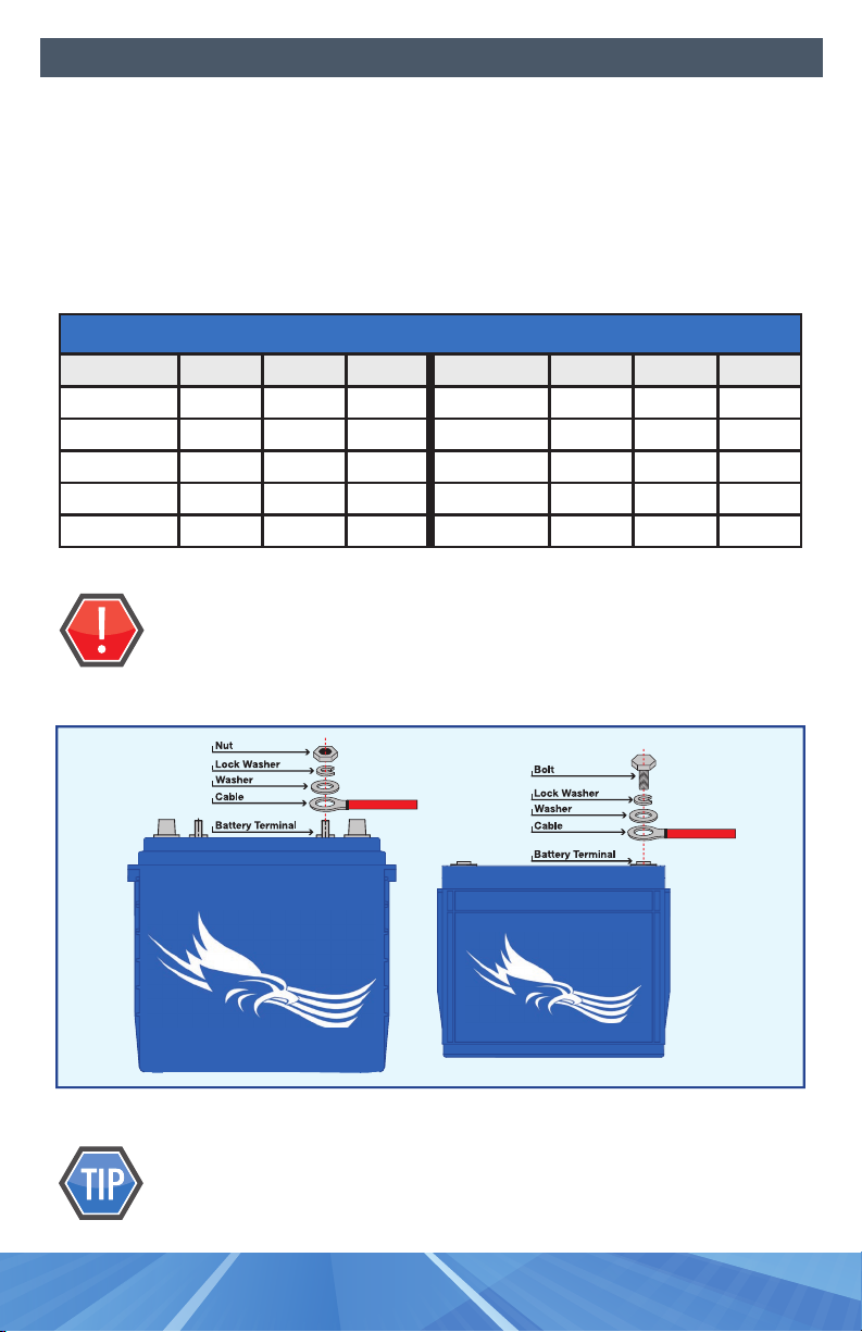
2.2 - Terminal connections
2.3 - Battery orientation
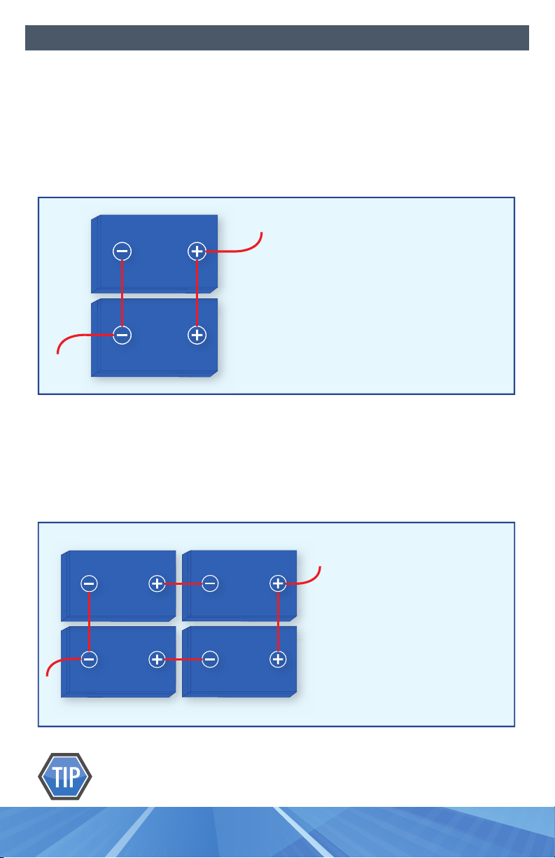
2.4 - Series connections
2.5 - Parallel connections
2.6 - Series / parallel connections
2.7 - Cross tying batteries in parallel packs
2.8 - Charging batteries before use
3. OPERATION ................................................. 8-9
3.1-Temperatureeectsonbatteryperformanceandlife
3.2 - Operating temperature range
3.3-Lowdischargerateeects
3.4 - Depth of Discharge (D.O.D.) vs. Battery Life
4. CHARGING ................................................10-11
4.1 - Charger inspection
4.2 - Charging your Fullriver batteries
4.3 - Charging temperature range
4.4 - Charging parameters
4.4.1 - Current
4.4.2 - Voltage settings
4.4.3 - Temperature compensation
5. STORAGE..................................................12-13
5.1-Batterystorageprocedure
5.2-Temperatureeectsonself-discharge
5.3 - Storage temperature range
6. TESTING ..................................................14-16
6.1 - Test preparation
6.2 - Open circuit voltage test
6.3 - Discharge test
6.4 - Optional test
6.5 - CCA test
6.6 - Battery replacement instructions
7. YOUR CLEAN-GREEN ENERGY SOLUTION ......................16-17
7.1-Fullriverproducts
7.2 - Fullriver manufacturing
7.3-Solarsettingrecommendations
8. TRANSPORTATION INFORMATION...............................18
A. APPENDIX ....................................................19
A.1 - Temperature ranges
A.2 - State of Charge (S.O.C.) vs. Open Circuit Voltage (O.C.V.)
A.3-Bolt/NutSpecications

Page d
Notes
INSTALLATION AND
OPERATION MANUAL

Page 1
INSTALLATION AND
OPERATION MANUAL

Page 2
BeforeinstallingyourFullriverbattery,pleaseadheretothefollowingsafety
guidelinesandmakesurethatyouhavetheproperequipmentforinstallation,
operation,anddiagnostictesting.
1.1 - SAFETY
PROTECT YOURSELF AND PROTECT YOUR BATTERY
•Wearprotectivegear,includinggloves,whenhandlingabattery.
•Installandremoveabatteryusingtheliftinghandlesprovided.
•Useawrenchwitharubbercoatedhandleforinstalling,tightening,or
removing battery connections.
• Do not place any objects on top of a battery.
• Do not smoke near a battery.
•Keepames,sparksandmetalobjectsawayfromabattery.
•Chargebatteriesinaventilatedarea-althoughAGMandGelbatteries
typicallydonotreleasegas.Thesafetyvalvemayopentoalleviateexcess
pressureifthebatteryisover-charged.
ALWAYS USE CAUTION AROUND A BATTERY
1.2 - EQUIPMENT CHECKLIST
Gloves
Wrenchwithinsulated/rubbercoatedhandle
Voltmeter
Charger
Discharger (if available)
Getting Started

Page 3
Properbatteryinstallationistherststepingettingthebestperformanceoutof
your Fullriver battery.
2.1 - SELECTING THE APPROPRIATE CABLE SIZE
Cablesmustbesizedtocarrythemaximumexpectedload.Under-sizedcablescan
resultinover-heating,meltedconnectionsandareapotentialrehazard.
Refer to TABLE 1 below for the current carrying capacity by cable size. These values
are for cable lengths of 6 feet (1.83 meters) or less. It is preferable that all cables in a
series connection or in a parallel connection are the same length.
Tosignicantlyreducetheamountofheatgeneratedattheterminals,
usecableswithsolder-dippedends.
Installation
25
30
40
55
75
95
130
150
170
265
360
Ampacity (Amps)
14
12
10
8
6
4
2
1
1/0
2/0
3/0
Cable Gauge (AWG)
TABLE 1

Page 4
2.2 - TERMINAL CONNECTIONS
Terminalconnectionsmustbetightenedusingthecorrecttorquevaluesasdened
in TABLE 2below.Overorundertightenedconnectionscanresultinterminal
breakage,over-heatingand/ormeltdown.Usingthepropertorquevaluewillprovide
optimumconductivity.Toavoidashortcircuit,useawrenchwithaninsulatedor
rubbercoatedhandlewhenmakingterminalconnections.SeeDIAGRAM 1 below
for proper washer placement.
NEVER place a washer between the mating surfaces of the terminals
andcables.Thiswillcompromiseelectricaltransmissionandincrease
resistance,resultinginextremeheatgenerationandprobableterminal
melting.
Loctite®Threadlockermaybeusedtobettersecuretheterminal
connections. Be careful not to get Loctite®between the mating surfaces
of the terminal.
Installation
DIAGRAM 1
Terminal Type ft-lbs lbs-in Nm Terminal Type ft-lbs lbs-in Nm
M6, AP 4.1-5.8 50-70 5.6-7.9 M10M (Stud) 7.7-9.6 92-115 10.4-13
M8 7.1-7.9 85-95 9.6-10.7 3/8” Stud 8.9-12 106-150 12-16.9
M10 9.6-12 115-141 13-16 FR45 5.8-7.4 70-90 7.9-10.1
M6M (Stud) 3.3-4.6 40-56 4.5-6.3 TP06 (AP) 3.3-4.6 40-56 4.5-6.3
M8M (Stud) 4.9-6.3 58-75 6.6-8.5 TP08/TP68 (AP) 5.2-6.9 63-83 7.1-9.4
TERMINAL TORQUE SPECS

Page 5
2.3 - BATTERY ORIENTATION
Theidealplacementofbatteriesisupright.AGMandGelbatteriescanbeplacedon
theirsideifnecessary.Itispreferredthatallthebatterieswithinapackbeplacedin
the same orientation.
NEVERplacebatteriesinaninvertedorientation(terminalspointed
towardsground).
2.4 - SERIES CONNECTIONS
Thereismorethanoneoptiontomeetyourvoltagerequirements.Forexample,for
a12voltsystem,youmayuseone(1)12voltbatteryortwo(2)6voltbatterieswired
inaseriestomakeupthe12volts.Youmayuseasmanybatteriesasyouneedto
make up the system voltage. Connect the positive of one battery to the negative
ofthenextthroughtheentirestring.SeeDIAGRAM 2 below for the proper series
connection.
Installation
Series Connection:
Voltage is increased in a series connection
Two 6V, 224AH batteries = 12V, 224AH
DIAGRAM 2

Page 6
2.5 - PARALLEL CONNECTIONS
Thereismorethanoneoptiontomeetyourenergyrequirements.Forexample,to
meet the requirements for a 210 Amp-Hour system, you may use one (1) 210
Amp-Hourbatteryortwo(2)105Amp-Hourbatterieswiredinparalleltomakeup
the210Amp-Hours.Connectallthepositiveterminalstogetherandallthenegative
terminals together in the string. See DIAGRAM 3 below for proper parallel
connection.
2.6 - SERIES / PARALLEL CONNECTIONS
Batteriescanbeconnectedinbothseriesandparalleltoattainthedesiredsystem
voltageandenergyrequirements.SeeDIAGRAM 4 below for proper series / parallel
connections.
Foroptimumperformance,thesystemspositiveandnegativeleads
shouldbeconnecteddiagonallyopposite(catty-corner)fromeachother.
Installation
Parallel Connection:
Capacity is increased in a parallel connection
Two 12V, 105AH batteries = 12V, 210AH
DIAGRAM 3
Series/Parallel Connection:
Voltage and capacity are increased in a
series/parallel connection
Four 12V, 115AH batteries = 24V, 230AH
DIAGRAM 4

Page 7
2.7 - CROSS TYING BATTERIES IN PARALLEL PACKS
Inordertomaintainbalanceinparallelbatterypacks,itisbesttocrosstiethe
batteries.Thismethodofconnectionwillmaximizetheperformanceandlifeofyour
batterysystem.Cross-tyingbatteriesmeansconnectingpositivetopositivesand
negativestonegativesofeachadjacentbatteryintheset.SeeDIAGRAM 5 below for
propercrosstyingconnections.Thedottedlinesrepresentthecrosstiedcables.
Leavesomespacebetweenbatteriesforairowandminorbattery
expansion.
2.8 - CHARGING BATTERIES BEFORE USE
NewAGMorGelbatteriesthathaveonlybeenstoreduptosixmonthswillnotneed
tobechargedpriortobeingputintoservice.
IfnewAGMorGelbatterieshavebeenstoredformorethansixmonths,and/orin
anexceptionallyhotenvironment,achargemaybenecessarypriortobeingputinto
service.Also,ifthebatteriesarenotchargedpriortobeingputintoservice,youmay
experienceaslightreductioninrangeontherstcycle.
Checktheopencircuitvoltage(O.C.V.)ofeachbatteryinthesetandifanybattery
within the set is less than the values in TABLE 3 above, recharge the battery set.
Installation
< 2.0 Volts
< 6.2 Volts
< 8.3 Volts
< 12.5 Volts
< 16.7 Volts
Open Circuit Voltage (O.C.V.)
2 Volt
6 Volt
8 Volt
12 Volt
16 Volt
Battery Nominal Voltage
TABLE 3
DIAGRAM 5

Page 8
Theperformanceandlifeofabatterywillvarywiththeapplication,usage,
temperatureanddepthofdischarge.AGMandGelbatteriestendtodeliverahigher
capacitythanrated(upto10-15%higher)untiltheyarebrokenin(approximately30
cycles)andsettleattheirratedcapacity.
3.1 - TEMPERATURE EFFECTS ON BATTERY PERFORMANCE AND LIFE
Operatingbatteriesabove80°F(27°C)willyieldruntimesabovetheratedcapacity
whileoperatingbatteriesbelow80°F(27°C)willyieldruntimesbelowtherated
capacity.Coldtemperaturescansignicantlyreducebatterycapacity(asshownin
the chart below).
Although higher temperatures increase the battery capacity, they also accelerate
corrosionandreduceoverallbatterylife.Forexample,batteriesoperating
continuouslyat100°F(37.8°C),couldexperienceasmuchasa25%reductioninlife.
3.2 - OPERATING TEMPERATURE RANGE
Operation
-40°F to 160°F
(-40°C to 71°C)
Maximum
5°F to 104°F
(-15°C to 40°C)
Recommended
TABLE 4

Page 9
3.3 - LOW DISCHARGE RATE EFFECTS
Batterycyclelifewillbereducedwhentheconstantloadappliedinacyclic
applicationisatorbelow0.7%ofthetotalAhinthebatterybank(C20rating).Thisis
duetoahigherrateofsulfationoccuringinthemiddleoftheplatethatwillcausea
reductioninavailablecapacitywhichinturnsincreasesthedepthofdischargeover
time.Aneorttoeitherincreasetheloadabove0.7%ofC20and/orreducethesize
ofthebatterybank’scapacitysotheloadisabove0.7%ofC20shouldbeputforthif
possible.
3.4 - DEPTH OF DISCHARGE VS. BATTERY LIFE
Batterycyclelifewillvarysignicantlydependingonthedepthofdischarge.The
deeperthedepthofdischarge,thefewerthecyclesabatterywilldeliver.Conversely,
theshallowerthedepthofdischarge,themorecyclesabatterywilldeliver(asshown
in the chart below).
Tooptimizethehealthofyourbattery,limitdischargeto80%orless.
Operation
CYCLE LIFE vs DEPTH of DISCHARGE (DOD)
100%
90%
80%
70%
60%
50%
40%
30%
20%
10%
0%
DOD
0 500
LIFE CYCLES (per BCI)
1000 1500 2000 2500 3000 40003500 4500 5000 5500 6000
*(Based on BCI Testing @ 2-hr Rate)

Page 10
UsingtheproperchargeriscriticaltotheperformanceandlifeofyourAGM
orGelbattery.IfyouarenotsureifyouhavetherightchargerforAGMorGel
batteries, please call our technical support line at (800) 522-8191 or email help@
fullriverbattery.comforverication.
4.1 - CHARGER INSPECTION
1. Thechargercableshouldbeinsulatedandfreeofbreaksorcuts.
2. Thecableconnectorsshouldbecleanandproperlymatedwiththebattery
terminals to ensure a snug connection.
3. Thecharger’sACcordshouldbefreeofbreaksorcutsandthewallplug
shouldbeclean.
4.2 - CHARGING YOUR BATTERIES
1. UseanAGMchargerorsettingwheneveravailableforAGMbatteries.Usea
GelchargerorsettingwheneveravailableforGelbatteries.
2. NeveruseaGELchargerorsettingonanAGMbattery,asitwillundercharge
thebatteryandsignicantlyreducebatterycapacityandlife.
3. Many,butnotall,wetbatterychargerswillworkforanAGMbattery.Call
toverifyyourcharger.Bepreparedtoprovidethemakeandmodelofyour
charger.
4. Batteriesshouldbefullychargedaftereachuse.Opportunitychargingcanbe
done,butthebatteriesshouldbefullychargedatleasteveryotherdayifthey
areuseddaily.
5. Chargeinaventilatedarea,asgasesmaybereleasedthroughthepressure
reliefvalveifthebatteriesareexcessivelyover-charged.
6. Ifthechargerdoesnothavetemperaturecompensation,avoidchargingat
temperatures above 122°F (50°C).
4.3 - CHARGING TEMPERATURE RANGE
4.4 - CHARGING PARAMETERS
Mostchargerscomepre-setfromthefactory.Ifyourchargerispre-programmed,
usetheinformationbelowtocheckifthesettingsarecompatiblewithAGMor
Gelbatteries.Ifyouhaveaprogrammablechargerorinverter,usethefollowing
information for settings.
Charging
Yes
No
5°F to 122°F (-15°C to 50°C)
32°F to 104°F (0°C to 40°C)
Temp Compensation Recommended
TABLE 5
-40°F to 160°F (-40°C to 71°C)
5°F to 122°F (-15°C to 50°C)
Maximum

Page 11
4.4.1 - CURRENT
All Models (excl. FSG): The recommendedbulkcurrentis20-25%ofthe20HrAH
capacityor0.20xC20(20Hr.capacityinAH).Themaximum allowable bulk current is
35%ofthe20Hr.AHcapacityor0.35xC20(20Hr.capacityinAH),unlessspecied.
Example:
DC115-12 is rated at 115AH @ 20 Hrs.
The recommended bulk current is 0.20 x 115 = 23 Amps
The maximum bulk current is 0.35 x 115 = 40 Amps
FSG Series: The recommendedbulkcurrentis12.5%ofthe10Hr.AHcapacityor
0.125xC10(10Hr.capacityinAH).Themaximumallowablebulkcurrentis15%of
the10Hr.AHcapacityor0.15xC10(10Hr.capacityinAH),unlessotherwisestated.
Example:
FSG1660-2 is rated at 1110AH @ 10 Hrs.
The recommended bulk current is 0.125 x 1110 = 139 Amps
The maximum bulk current is 0.15 x 1110 = 167 Amps
4.4.2 - VOLTAGE SETTINGS (BOLD IS RECOMMENDED SETTING)
4.4.3 - TEMPERATURE SETTINGS
If you have a programmable charger or inverter that has a temperature
compensationsetting,itshouldbesetto-4mV/°C/cellor-2mV/°F/cell.TABLE
8below has the temperature compensation voltage values for a 12V battery. For a
24V, 36V or 48V system, multiply the values in the table by 2, 3 or 4 respectively.
Charging
TABLE 6
Bulk
Absorption
Float
Charge State
14.4-14.7 V
14.4-14.7 V
13.6-13.7 V
12 Volt AGM
19.2-19.6 V
19.2-19.6 V
18.2 V
16 Volt AGM
28.8-29.4 V
28.8-29.4 V
27.2-27.4 V
24 Volt AGM
57.6-58.8 V
57.6-58.8 V
54.4-54.8 V
48 Volt AGM
Bulk
Absorption
Float
Charge Stage
15.30 V
15.30 V
14.25 V
32°F (0°C)
15.06 V
15.06 V
14.01 V
50°F (10°C)
14.82 V
14.82 V
13.77 V
68°F (20°C)
14.70 V
14.70 V
13.65 V
77°F (25°C)
14.58 V
14.58 V
13.53 V
86°F (30°C)
14.34 V
14.34 V
13.29 V
104°F (40°C)
TABLE 8
TABLE 7
Bulk
Absorption
Float
Charge State
14.4-14.7 V
14.4-14.7 V
13.6 V
12 Volt FSG
28.8-29.4 V
28.8-29.4 V
27.2 V
24 Volt FSG
57.6-58.8 V
57.6-58.8 V
54.6 V
48 Volt FSG
14.1-14.4 V
14.1-14.2 V
13.6 V
12 Volt DCG

Page 12
AGMandGelbatterieshaveamuchlongershelflifethanwet,lead-acidbatteries.
Withaself-dischargeofonly1-3%permonth,AGMandGelbatteriescanbestored
forayearorlongerwithoutneedingtobecharged.
5.1 - BATTERY STORAGE PROCEDURE
1. Chargebatteriesbeforetheyareplacedinstorage.
2. Disconnectbatteriesfromtheequipmentandchargertoeliminateany
parasiticloads.
3. CheckthebatteriesbasedonconditionsandscheduleinTABLE 9 below.
4. Check the open circuit voltage (OCV) of each battery in the set. If any battery
within the set is less than the values in TABLE 10 below, recharge the battery
set.
5. Ifthechargerhasamaintenancemode,selectthatmodetoboostcharge
batteries. Otherwise, run the normal charge cycle.
6. IfthebatteriesarestoredshorterthanthetimeperiodsinTABLE 9,theydo
notneedtoberechargedpriortobeingputbackintoservice.
AGMandGelbatteriesdonothaveamemoryeect;sothereisnoneed
tofullydischargebatteriespriortocharging.
Storage
9 months
6 months
3 months
Time
Below 68°F (20°C)
68°F to 86°F (20°C to 30°C)
Above 86°F (30°C)
Temperature
TABLE 9
< 2.0 Volts
< 6.2 Volts
< 8.3 Volts
< 12.5 Volts
< 16.7 Volts
Open Circuit Voltage (O.C.V.)
2 Volt
6 Volt
8 Volt
12 Volt
16 Volt
Battery Nominal Voltage
TABLE 10

Page 13
Storage
5.2 - TEMPERATURE EFFECTS ON SELF-STORAGE
Ifthestorageenvironmentishot,batterieswillself-dischargefasterthanina
coldenvironmentasshowninthechartbelow.TheFSGserieswilldischarge
approximately40-60%slowerabove86°Fthanthechartbelowindicates.
BatteriesCANbesafelystoredonconcreteoorswithoutanynegative
eects.ConcreteoorsDONOTdrainbatteries.
5.3 - STORAGE TEMPERATURE RANGE
Storebatteriesinacool,dryenvironmenttominimizeselfdischarge.
-40°F to 160°F (40°C to 71°C)
Maximum
5°F to 122°F (-15°C to 50°C)
Recommended
TABLE 11

Page 14
Testingbatteriescanbecomplexandtherearemanyapplicationspecicvariables
thatcannotbeconsideredinonesimpletest.Thissectionisaguidetohelpyou
determinetheoverallconditionofyourbatteries.ContactyourlocalFullriverBattery
distributorforassistance.
6.1 - TEST PREPARATION
1. Checkthatthebatterycablesareingoodworkingcondition.Replaceany
damagedorbrokencables.
2. Checkthatallterminalconnectionsaretightenedtopropertorque
specicationasdescribedinTABLE 2.
3. Fully charge batteries.
4. Let batteries rest for at least 8 hours once charging is complete.
6.2 - OPEN CIRCUIT VOLTAGE TEST
1. Checkandrecordopencircuitvoltage(O.C.V.)ofeachbattery.
2. If all of the batteries are below 2.0V (2V battery), 6.1V (6V battery), 8.1V (8V
battery),12.2V(12Vbattery),or16.3V(16Vbattery)thesethasfailed.Replace
theentiresetofbatteries.Inthissituation,thebatterysethaseitherprovided
allofitsavailableenergyorwasseverelyabused.
3. Otherwise, any battery that is 0.15V lower than the highest battery voltage (2V
battery), 0.25V lower than the highest battery voltage (6V battery), 0.35V lower
than the highest battery voltage (8V battery), 0.5V lower than the highest
battery voltage (12V battery), 0.7V lower than the highest battery voltage (16V
battery),mighthavefailed.Makenoteofthesebatteries.
Allbatteriesinagoodsetshouldbeabove2.1V(2Vbattery),6.4V(6Vbattery),8.5V
(8Vbattery),12.7V(12Vbattery),and17.0V(16Vbattery)whenfullychargedafterat
least 8 hours of rest.
6.3 - DISCHARGE TEST (if you do not have a discharger, proceed to section 6.4. if you
have a Full Throttle series battery, proceed to section 6.5)
1. Connectandstartdischarger.
2. Recordminutes(runtime)whendischargeiscomplete.Correctruntime
minutes for battery temperature using the following formula:
Mc = Mr [1 - 0.009 (T-27)]
Where Mcisthecorrectedminutes,MristheminutesrecordedandTis the
temperatureattheendofthedischargein°C.
Testing

Page 15
3. Ifthesetrunsmorethan60%ofitsratedcapacity,thebatteriesaregoodand
the test is complete.
4. Ifthesetrunslessthan60%ofitsratedcapacity,reconnectthedischarger.
Whileunderthedischargeload,recordtheendofthedischargevoltagefor
each battery.
5. Thebatteriesthatare0.5Vlowerthanthehighestendofdischargevoltage
shouldbenoted.
6. Ifthesetdeliveredlessthan60%ofitsratedcapacity,andthesamebatteries
thatwerenotedinSTEP 3 of SECTION 6.2werealsotheonesnotedinSTEP 5
of SECTION 6.3,thosebatteriesaremostlikelyfailedandshouldbereplaced.
Follow the replacement instructions in SECTION 6.6 below.
7. Otherwise,pleasecontactyourlocalFullriverBatterydistributortoreview
yourdataindetail.Youcanalsoreachtechnicalsupportbycalling
mayberequireddependingonyourspecicapplication.
6.4 - OPTIONAL TEST
After completing SECTION 6.1andSECTION 6.2, follow these steps:
1. Operatethevehicle/equipmentuntilbatteryperformancedecreases.
2. Recordvoltagesduringandafteroperation.
3. Recordtimeanddistanceofoperation.
4. Providethevoltage,time,anddistancedatatoaFullriverBatterydistributor
or to Fullriver Battery technical support at (800) 522-8191 or email
5. Thisdatawillbeanalyzedincomparisontowhatisexpectedofthe
vehicle/equipment.
6.5 - CCA TEST (only applicable to Full Throttle series batteries)
1. ConnectandstartcarbonpileloadtesteraccordingtoCCAratinglistedon
battery.
2. Recordalldataduringtest(startvoltage,endvoltage,pass/fail,testermodel,
etc.).
3. Providethevoltage,time,andtesterdatatoaFullriverBatterydistributoror
to Fullriver Battery technical support at (800) 522-8191 or email
Testing

Page 16
6.6 - BATTERY REPLACEMENT INSTRUCTIONS
Aslongasitissafetodoso,chargethesetofbatteriesbeforereplacingthefailed
onestomakesurethegoodbatteriesarefullycharged.
Ifpossible,replacefailedbatterieswithgoodbatteriesaroundthesameagefrom
anotherpieceofequipment.Trytoavoidmixingnewbatteriesinequipmentwithold
batteries. Put all new batteries in the same piece of equipment.
7.1 - FULLRIVER PRODUCTS
FullriverBatteryproducessealed,maintenance-freebatteriesthatarenon-
hazardous,non-spillable.Duringnormaloperation,ourbatterieswillnotreleaseany
harmfulgasesandwillnotleakanyacidicelectrolyteintotheenvironment.
Fullriverbatteriesareclassiedassafeforair,sea,andgroundtransportation.They
meet all requirements of the International Air Transport Association (I.A.T.A.), the
InternationalCivilAviationOrganization(I.C.A.O.),theInternationalMaritime
DangerousGoods(I.M.D.G.),andtheDepartmentofTransportation(D.O.T.).
Morethan98%oftheleadinbatteriesisrecycled-placinglead-acidbatteriesatthe
topofthelistofmosthighlyrecycledconsumerproducts.Therecyclingloopofa
lead-acidbatterygoesonindenitely.
7.2 - FULLRIVER MANUFACTURING
FullriverBatterymanufacturesbatteriesinaccordancewithinternational
environmentalregulations.Wecontinuallyimproveourprocessinordertominimize
waste,recycleallwastethatisrecyclableanddiscardwastethatisnotrecyclablein
accordancewithlocaldisposalregulations.Westrictlyenforcetheuseofproper
ventilationandprotectivegear.Thisenforcementhelpsminimizeemployee
exposuretoleadatapointwellbelowsuggestedlevels.
7.3 - SOLAR SETTING RECOMMENDATIONS
FullriverBatteryhasasignicantpresenceandhistoryintheresidential,commercial,
andRVsolarmarkets.Fromthishistory,weprovidethefollowingrecommendations
onchargecontrollerandinvertersettings:
7.3.1 - VOLTAGE SETTINGS
Pleaseseetables6&7onPage11forbulk,absorption,andoatvoltage
recommendations.
RebulkVoltageshouldbesetlowenoughtonotcausetwochargecyclesinoneday,
typically12.0,24.0,or48.0V.ReoatVoltageshouldbesetslightlyunder100%OCV
or 12.7, 25.4, or 50.8V.
Testing & Your Clean-Green Energy Solution
This manual suits for next models
4
Table of contents