1-2-2 T6600SFTY
ing is performed that involves B+, horizontal de-
flection or high voltage. Correct operation of the
X-radiation protection circuits also must be recon-
firmed each time they are serviced. (X-radiation
protection circuits also may be called "horizontal
disable" or "hold down.") Read and apply the high
voltage limits and, if the chassis is so equipped,
the X-radiation protection circuit specifications giv-
en on instrument labels and in the Product Safety
& X-Radiation Warning note on the service data
chassis schematic. High voltage is maintained
within specified limits by close tolerance safety-re-
lated components/adjustments in the high-voltage
circuit. If high voltage exceeds specified limits,
check each component specified on the chassis
schematic and take corrective action.
2. Read and comply with all caution and safety-relat-
ed notes on or inside the receiver cabinet, on the
receiver chassis, or on the picture tube.
3. Design Alteration Warning - Do not alter or add
to the mechanical or electrical design of this TV re-
ceiver. Design alterations and additions, including,
but not limited to circuit modifications and the ad-
dition of items such as auxiliary audio and/or video
output connections, might alter the safety charac-
teristics of this receiver and create a hazard to the
user. Any design alterations or additions will void
the manufacturer's warranty and may make you,
the servicer, responsible for personal injury or
property damage resulting therefrom.
4. Picture Tube Implosion Protection Warning -
The picture tube in this receiver employs integral
implosion protection. For continued implosion pro-
tection, replace the picture tube only with one of
the same type number. Do not remove, install, or
otherwise handle the picture tube in any manner
without first putting on shatterproof goggles
equipped with side shields. People not so
equipped must be kept safely away while picture
tubes are handled. Keep the picture tube away
from your body. Do not handle the picture tube by
its neck. Some "in-line" picture tubes are equipped
with a permanently attached deflection yoke; be-
cause of potential hazard, do not try to remove
such "permanently attached" yokes from the pic-
ture tube.
5. Hot Chassis Warning -
a. Some TV receiver chassis are electrically connect-
ed directly to one conductor of the AC power cord
and maybe safety-serviced without an isolation
transformer only if the AC power plug is inserted
so that the chassis is connected to the ground side
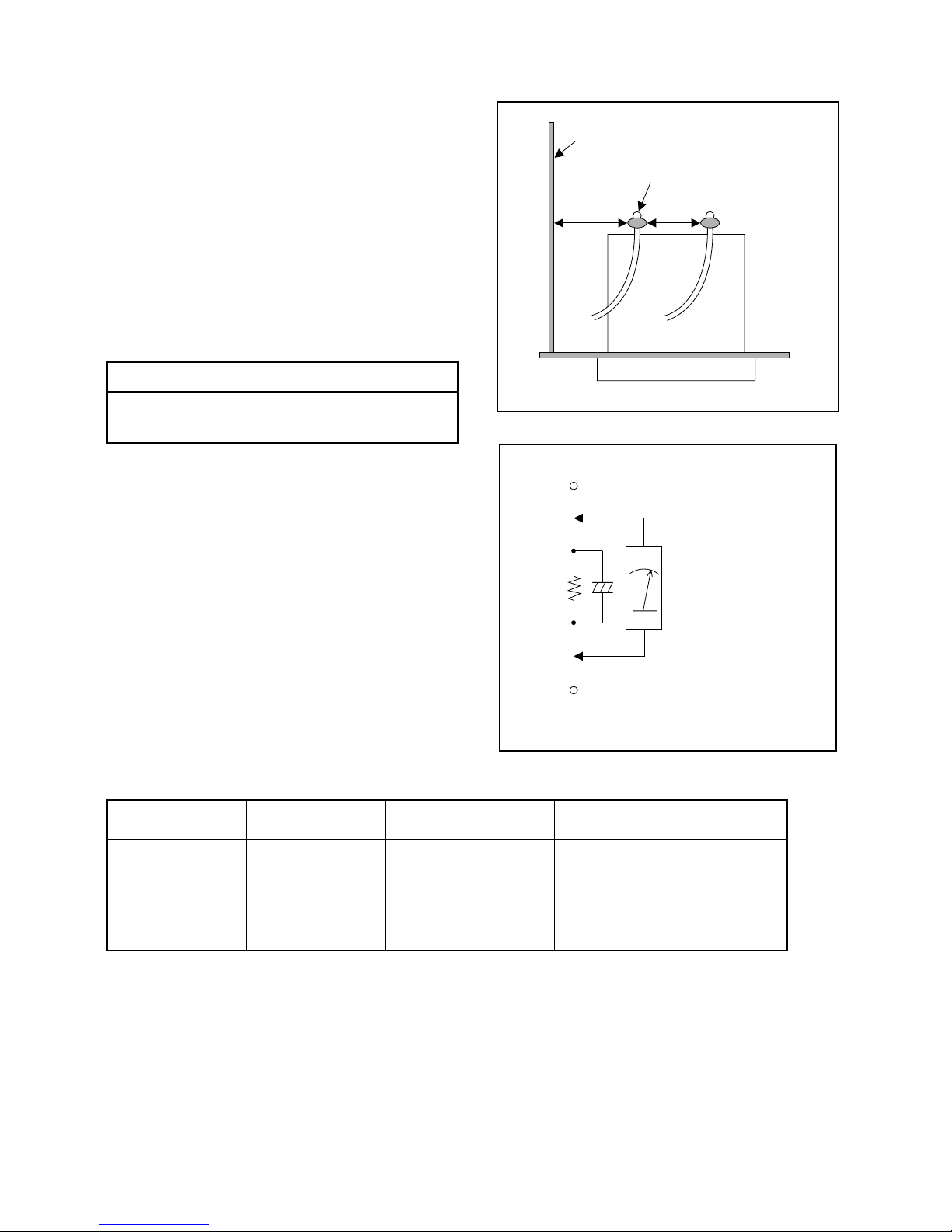
of the AC power source. To confirm that the AC
power plug is inserted correctly, with an AC volt-
meter, measure between the chassis and a known
earth ground. If a voltage reading in excess of 1.0V
is obtained, remove and reinsert the AC power
plug in the opposite polarity and again measure
the voltage potential between the chassis and a
known earth ground.
b. Some TV receiver chassis normally have 85V
AC(RMS) between chassis and earth ground re-
gardless of the AC plug polarity. This chassis can
be safety-serviced only with an isolation transform-
er inserted in the power line between the receiver
and the AC power source, for both personnel and
test equipment protection.
c. Some TV receiver chassis have a secondary
ground system in addition to the main chassis
ground. This secondary ground system is not iso-
lated from the AC power line. The two ground sys-
tems are electrically separated by insulation
material that must not be defeated or altered.
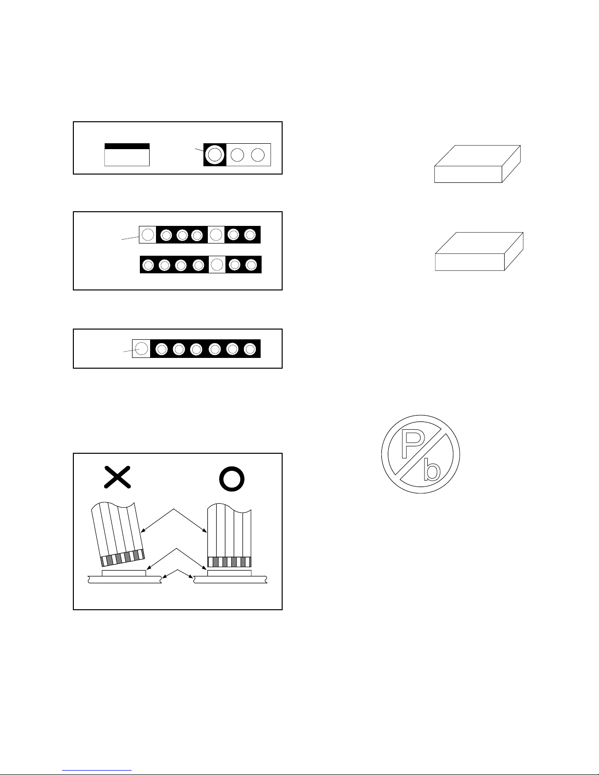
6. Observe original lead dress. Take extra care to as-
sure correct lead dress in the following areas: a.
near sharp edges, b. near thermally hot parts-be
sure that leads and components do not touch ther-
mally hot parts, c. the AC supply, d. high voltage,
and e. antenna wiring. Always inspect in all areas
for pinched, out of place, or frayed wiring. Check
AC power cord for damage.
7. Components, parts, and/or wiring that appear to
have overheated or are otherwise damaged
should be replaced with components, parts, or wir-
ing that meet original specifications. Additionally,
determine the cause of overheating and/or dam-
age and, if necessary, take corrective action to re-
move any potential safety hazard.
8. Product Safety Notice - Some electrical and me-
chanical parts have special safety-related charac-
teristics which are often not evident from visual
inspection, nor can the protection they give neces-
sarily be obtained by replacing them with compo-
nents rated for higher voltage, wattage, etc.. Parts
that have special safety characteristics are identi-
fied by a ( !) on schematics and in parts lists. Use
of a substitute replacement that does not have the
same safety characteristics as the recommended
replacement part might create shock, fire, and/or
other hazards. The Product's Safety is under re-
view continuously and new instructions are issued
whenever appropriate. Prior to shipment from the
factory, our products are strictly inspected to con-
firm with the recognized product safety and electri-
cal codes of the countries in which they are to be
sold. However, in order to maintain such compli-
ance, it is equally important to implement the fol-
lowing precautions when a set is being serviced.