Furuno FAR-2107 Series User manual

スタンダードコンソール
組込み要領書
RCN-003/004
Standard Console
Installation Manual
www.furuno.com
Model
STANDARD RADAR CONSOLE
FAR-2107/2807シリーズレーダーコンソール
FAR-2107/2807 Series Radar Console

Pub.No. C32-00406-E
(2009, AKMU) RCN-003/004
00015088214

1
FAR-2807/2107 SERIES RADAR Console RCN-003/004
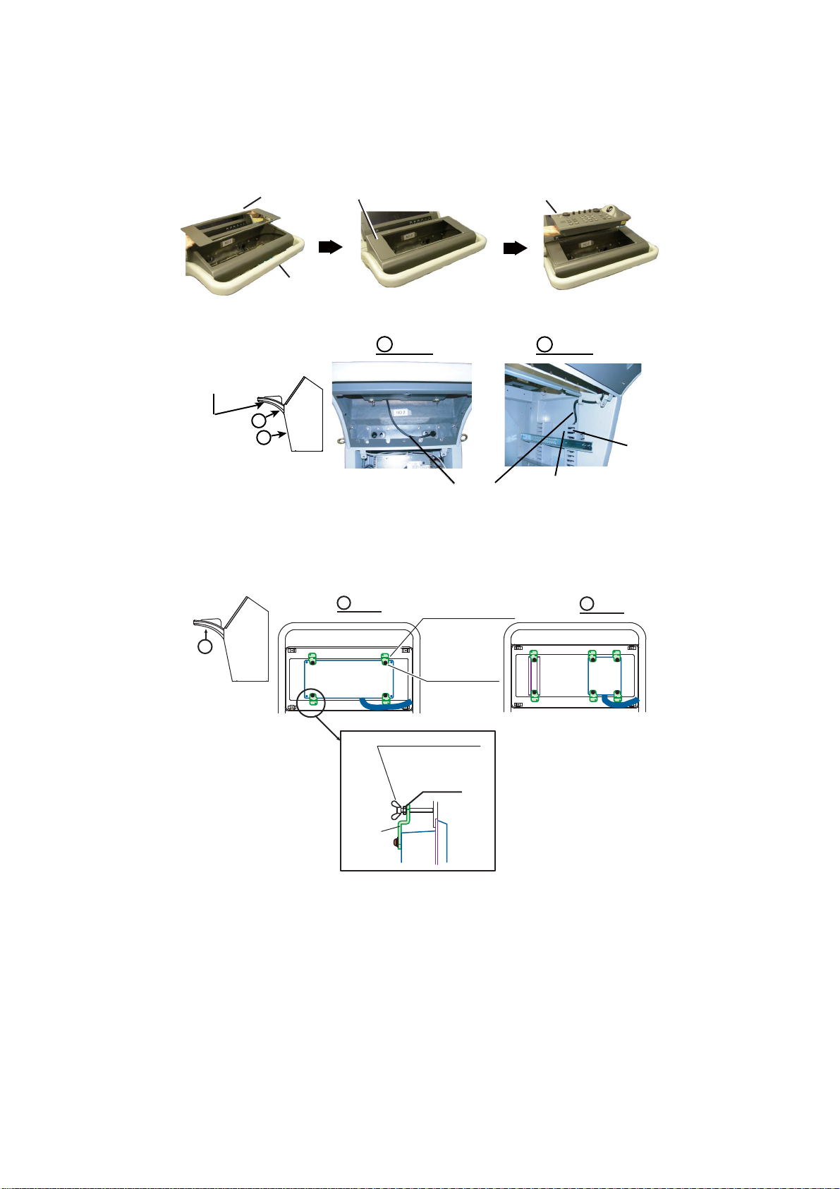
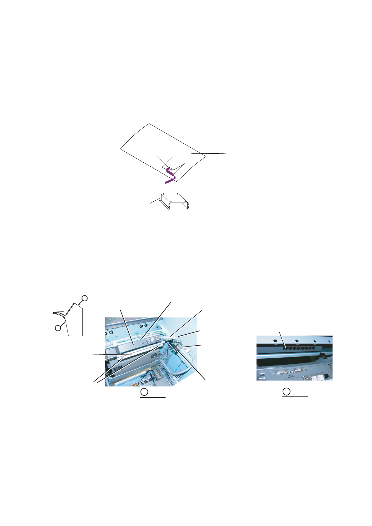
Installation Procedure
The components of the radar console are either assembled at the factory or require assembly in the
field. The purpose of this technical information is to provide the procedures for in-the-field installation
of the processor unit, monitor unit, control unit and optional equipment of the radar console.
There are eight types of radar console kits, as shown below. For further details, see the packing list
at the back of this manual.
Radar console installation kits
Type: RCN-003-14, Code No.: 000-083-519 (for MU-231CR/MU-231, RCU-014)
Type: RCN-003-15, Code No.: 000-083-520 (for MU-231CR/MU-231, RCU-015)
Type: RCN-003-S-14, Code No.: 000-083-521 (for MU-231CR/MU-231, S-band; RCU-014)
Type: RCN-003-S-15, Code No.: 000-083-522 (for MU-231CR/MU-231, S-band; RCU-015)
Type: RCN-004-14, Code No.: 000-083-523 (for MU-201CR/MU-190, RCU-014)
Type: RCN-004-15, Code No.: 000-083-524 (for MU-201CR/MU-190, RCU-015)
Type: RCN-004-S-14, Code No.: 000-083-525 (for MU-201CR/MU-190, S-band; RCU-014)
Type: RCN-004-S-15, Code No.: 000-083-526 (for MU-201CR/MU-190, S-band; RCU-015)
Optional equipment of the radar console are as below.
• Gyro converter kit GC-10-4, Code No.: 000-083-528
• DVI-RGB conversion kit OP03-180-4*, Code No.: 008-545-600
• BNC connector converter DSUB-BNC-1-RCN3/4*, Code No.: 008-545-850
• Switching Hub HUB-100-RCN3/4, Code No.: 000-084-322
• Memory Card Interface Unit CU-200-FAR, Code No.: 000-081-568
• Video LAN converter IF-7100, Code No.: 000-026-912
• AC/DC power supply unit PR-240, Code: 000-013-632
*: When Video LAN converter IF-7100 is installed, DVI-RGB conversion kit and BNC connector
cannot be installed together.
If you are installing a factory-assembled console, follow step 1, step 24 and step 31.

2
Mounting and wiring of the console
1 Fasten the console.
1) Install a channel base (height: 100 mm), consulting with the shipyard.
2) Pass a lifting belt through the four eye bolts, hoist unit with crane and place unit on top of the channel
base.
3) Remove the front cover of the console by loosening two screws.
4) Fasten the console to the channel base with six hexagon head bolts (M12, local supply).
5) Remove four eye bolts. Cover the fourteen holes for the eye bolts with the brush clips supplied.
6) Connect an earth plate (protective earth, width: 50 mm) to the ground terminal inside the console at the
rear bottom. Run the earth plate through the cable entrance and then weld it to ship’s superstructure.
2 Fasten the monitor unit MU-201CR or MU-231CR to the console in the field. (For the monitor
unit MU-190 or MU-231, see page 16.)
#.#4/#.#4/
#%-#%-
((
4#,#
((
(( ((
'$.'$.
1((1(( 1010
23452345
5'05145'0514
%.'#4%.'#4
2.#02.#0
%06%061((1((
)*+)*+
678678 9:;<9:;<
%767%767
4
/10+614/10+614
*'.2*'.2
'06'4'06'4
&52&5256&56&
%*#46%*#46 #
,-.,-.
4'%14&4'%14&
/01/01
'8'06'8'06
6#4)'66#4)'6
##
4#0)'4#0)'
/'07/'07 /1$/1$
)#+0)#+0
#%4#+0#%4#+0
/#4-/#4-
$4+..$4+..
#$%#$%
$4+..$4+..2
&'(&'(
/1&'/1&'
#%5'##%5'#
1((1((
84/84/
1010
(6 - Φ15)
A
A
Eye Bolt, 4 pcs.
Processor
Unit
Front Cover
Terminal
Board Ground Terminal
Cable Clamp
View
Cable Entrance
Channel Base (Shipyard Supply)
Fixing Holes
Bottom Cover of
Console Panel
Console Panel Top Cover

3
1) Set cushioning material on the console table and then place the monitor unit on the material, LCD side
down. Connect the power cable (attached to the console), ground wire (attached to the console) and
cable assembly (DVI-D/D S-LINK 5M, attached to the console) to the monitor unit.
2) Attach the panel hooks (accessories for the monitor unit) to the location shown in the exploded view
below. Fasten the monitor unit to the console with four screws (M6×25).
3) Attach the cosmetic caps (accessories for the monitor unit) at four locations.
Cable Assembly
(DVI-D/D S-LINK 5M)
View
A
For MU-231CR
Power Cable
Ground Wire
Cable Clamp
Screw
Screw
(M4, 2 pcs.)
Connector Cover
Screw
(M4, 2 pcs.)
Pinch shield
and fasten it
with
two screws.
Hook
A
Pinch
between
plain
washers. Approx. 45°
For MU-201CR
Screw Attached
to Terminal Board
Conductor Side Conductor Side
Approx. 45°
View
Screw
(M6x25, 4 pcs.)
Monitor Unit
Panel Hook
Cosmetic Cap
Screw for Fixing
Monitor Unit
EXPLODED VIEW
Fixing Hole
Fasten monitor unit to console.

4
3 Fasten the control unit to the console.
1) Remove the bottom cover of the console panel and the duct cover attached to the right side of the con-
sole.
2) Set flush mount plate B (for RCU-014) or flush mount plate C (for RCU-015) to the console panel.
3) Set the control unit (RCU-014 or RCU-015) to the hole of the flush mount plate B or flush mount plate
C, which is set to the console panel.
4) Draw the signal cable from the control unit into the console and route it through the right duct.
5) Fasten the flush mount fixture (4 pcs. for RCU-014, or 6 pcs. for RCU-015) to the rear side of the control
unit (which is set to the flush mount plate B or flush mount plate C) with washer-head screws (M4×12).
6) Screw nut (M5) onto wing screw (M5×40). Screw in the wing screw in other hole in the flush mount fix-
ture to fasten the control unit to the console and then tighten the nut.
Flush Mount Plate Control Unit
Console Panel
View
A
Duct Cover (back)
Duct
Signal Cable from Control Unit
View
B
Bottom Cover of
Console Panel
A
B
View View
RCU-014
Flush Mount Fixture
RCU-014: 4 pcs.
RCU-015: 6 pcs.
RCU-015
Washerhead Screw
M4x12
RCU-014: 4 pcs.
RCU-015: 6 pcs.
Wing Screw M5x40
Control
unit
Flush
Mount
Fixture
A
A
A
RCU-014: 4 pcs.
RCU-015: 6 pcs.
Nut M5

5
4 Fasten the Memory Card Interface Unit CU-200 (option) to the console (see the accessories
at page A-12).
1) From the bottom cover of the console panel, remove round cap and replace it with grommet (supplied).
2) Set the CU-200 to the mounting bracket (19-023-3091) and fasten it with four washerhead screws
(M4×10).
3) Connect power cable, ground wire and LAN cable to the CU-200. Route those cables through the grom-
met and draw them into the console.
4) Fasten the CU-200 assembly to the bottom cover of the console panel with four each of spring washers
(M4), flat washers (M4) and nuts (M4). See the figure below.
5) Refasten the bottom cover of the console with ten screws (M4×15).
6) Route the power cable through the right duct.
5 Fasten the Switching Hub (option) to the console (see page A-13 and A-14).
1) Remove the top cover of the console by unfastening six screws (M4×8).
2) Fasten the hub mounting plate (03-163-7225) to the console with six washer-head screws (M4×10).
3) Set the right and left mounting legs of the Switching Hub to the bottom stoppers of the mounting plate.
4) Attach the hub fixing rubber to the hub fixing plate (03-163-7226). Fasten the top of the Switching Hub
with two washer-head screws (M4×15) and hub fixing plate.
5) Connect power cable (NR203PF-VVS1.25 0.3M), ground wire and LAN cable (P5E-4PTX-BL L=2M) to
the Switching Hub.
Grommet
Mounting Bracket
(Set the CU-200)
Bottom Cover of
Console Panel
View
A
Ground Wire
A
B
B
Switching Hub
HUB-100
Power Cable
(NR203PF-VVS1.25 0.3M)
Hub Mounting Plate
Washerhead Screw
(M4x10, 6 pcs.)
3 pcs. at either side
Terminal Board TB4
Hub Fixing Plate
Washerhead Screw
(M4x15, 2 pcs.)
LAN Port of Switching Hub
View

6
6 If the Video LAN converter IF-7100 is installed, do steps 6 to 7. Fasten the AC-DC Power
Supply unit PR-240 (option) to the console with the optional VLC installation kit OP03-233.
NOTE: If the DC power line is connected to IF-7100, the PR-240 is not required.
1) Fasten the PR-240 to the PR fixing plate (03-163-7276-0) with four upset hex. bolts (M5×12).
For FAR-2137S/2837S
The Power Supply Unit PSU-007 also is fastened to the PR fixing plate.
Remove the four screws (M4) then detach the cover of PSU-007. Fasten the PSU-007 to the PR fixing
plate with the upset UI hex. bolts (M5×12). Fasten the cover detached with the original screws.
2) Fasten the PR fixing plate assy. to the console with four upset bolts, referring to the figure below. Attach
the PR-240 so that the terminal block is upward.
3) Attach the Fixing beam assy. (OP03-233-1) to the console.
4) Attach the clamps as below.
PR-240
PR-240
Terminal block
Terminal block
PR fixing plate
PR fixing plate
PR fixing plate assy.
PSU-007
PSU-007
Screw (M4, 4 pcs.)
+Upset bolt
(M5×12, 2 pcs.)
+Upset UI bolt
(M6×12, 2 pcs.)
Beam assy., M6×12, 2 pcs.
VLC assembly
VLC assembly
PR-240PR-240
Rear left ductRear left duct
PR-240PR-240
Rear right ductRear right duct
Clamps
: CKS-20-H
: CKS-13-H

7
5) Remove the cover of the terminal block of PR-240 then connect
the AC power cable, the ground wire and the DC power cable to
the terminal block.
For FAR-2137S/2837S
Pass the two power cables and ground wire from PSU-007 through the rear left duct, then connect the
cables to the terminal board at the bottom of the console. See the figure "Terminal board at the bottom
of the console" on page 14 .
6) Connect the AC power cable from under the rear left duct to the Fixing beam assy.
7) Connect the ground wire from under rear left duct to
the ground point.
8) After wiring, fasten the cover of the terminal block on the PR-240 as shown below.
7 Fasten the Video LAN Converter IF-7100 (option) to the console with the optional VLC in-
stallation kit OP03-233.
1) Attach the two clamps to the console. Pass the ground
wire (AF214AMM-L2400) from the top of the rear right
duct then connect to the ground point.
2) Fasten the IF-7100 to the VLC fixing plate with
four binding screws (M4×12).
3) Attach the three clamps (CHS-20-H) to the
VLC fixing plate.
Cable Port Via point
AC power cable
(FV2W-VVS2.0X2C-L1450)
AC-IN port Pass through rear
left duct
Ground wire
(AF214AMM-L1700)
Ground
terminal
Pass through rear
left duct
DC power cable
(A1.5-10-FV2-4L1800)
DC OUT
port
Pass through rear
right duct
DC OUT
24 VDC
+ –
DC IN
24 VDC
+ –
AC IN
Terminal block on PR-240 (Top view)
Ground wire
Ground wire
AC power cable
AC power cable
DC power cable
DC power cable
Direction to connect the cables
Ground point
Ground point
Ground wire
Ground wire
Clamp
Clamp
Cover
Cover
Terminal block
Terminal block
PR-240
PR-240
Orient cover in
direction of arrow
Orient cover in
direction of arrow
Before wiring After wiring
Wiring
Clamp (2 pcs.)
Clamp (2 pcs.)
Pull out from
rear right duct
Pull out from
rear right duct
Ground wire
Ground wire
Ground point
Ground point
Binding screw
(M4×12,
4 pcs.)
Binding screw
(M4×12,
4 pcs.)
IF-7100
(VLC)
IF-7100
(VLC)
VLC fixing plate
VLC fixing plate
Clamps
Clamps

8
4) Fasten the VLC fixing plate support (R/L) to
the console with four upset UI bolts (M6×12).
5) Fasten the VLC fixing plate on the VLC fixing
plate support (R/L) with two upset UI bolts (M6×12) so that
the VLC fixing plate support touches the stopper of the VLC
fixing plate.
6) Connect the DVI cable to the Radar Processor Unit
then pass the DVI cable through two clamps.
7) Bind three cables (DC power cable, DVI ca-
ble, and ground wire to be connected to the
IF-7100) with a cable tie. Pass the cables be-
tween two ducts.
• DC power cable: to PR-240*
• DVI cable: to RPU-013
• Ground wire: to ground point (through
rear right duct)
*: When not installing PR-240, bind two ca-
bles (DVI cable and ground wire) with the ca-
ble tie.
When not installing PR-240
Connect the power cable between the termi-
nal block on the beam and IF-7100. Bind ex-
cess cable with a cable tie as shown right.
8) Connect the three cables to the IF-7100.
(4 pcs, left and right)
VLC fixing plate support
(2 pcs. left and right)
VLC fixing plate support
(2 pcs. left and right)
VLC fixing plate
VLC fixing plate
Bolt (M6×12, 2 pcs.
left and right)
Bolt (M6×12, 2 pcs.
left and right)
Stopper
Stopper
RPU
RPU
DVI cable
(DVI-DD
S-LINK 1.8M)
DVI cable
(DVI-DD
S-LINK 1.8M)
Clamp
(2 places)
Clamp
(2 places)
DC power cable
DC power cable
Ground wire
Ground wire
DVI cable
DVI cable
Cables
(pass between
two
ducts)
Cables
(pass between
two
ducts)
Duct
Duct
Cable tie
Cable tie
Terminal block
Terminal block
Power cable
Power cable
DVI cableDVI cable
Power cablePower cable
Ground wireGround wire

9
8 Remove the cover of the processor unit and open the upper case.
9 Remove the transparent cover from the TB board (03P9342) by loosening four washer-head
screws (M4×10). Disconnect all cable assemblies from the TB board and BRC board. These
assemblies may be discarded.
• J203 on the SPU board to J654 on the TB board
• J202 on the SPU board to J653 on the TB board
• J482 on the HV9017 board to J651 on the TB board
• J105 on the AC-PWR/DC-PWR board to J652 on the TB board/J661 on the BRC board
10 Remove the TB board from the processor unit.
11 To the processor unit, connect the cable assembly temporarily attached to the console and
pull out it from the cable entrance.
NOTE: The center of the cable assembly is covered with black nylon mesh. Connect the longer
side of the uncovered part of the cable assembly to the processor unit.
Processor Unit
J661
BRC PCB
03P9485
TB PCB 03P9342
J621
J620
J619
J618
J612
J610
J608
J607
J606
J605
J604
J603
J602
J601
J617
J616
PSU
J654
J615J614
J613 J609
J611
J651 J652
J653

10
12 Fasten the optional DVI-RGB conversion kit (OP03-180-4, see page A-11) in the processor
unit. For further details, see chapter 4 in the installation manual of the FAR-2807/2107 se-
ries.
NOTE: If IF-7100 is installed, the optional DVI-RGB conversion kit is not installed in the console.
13 Fasten the main part of the op-
tional gyro converter kit (GC-
10-4, see page A-10) in the
processor unit. Fasten the re-
lay connector (J680) of the
gyro converter kit to the TB
PCB mounting plate. See
chapter 4 in the installation
manual of the FAR-2807/2107
series how to fasten the Gyro
Converter board (64P1106A)
to the processor unit.
14 Close the upper case of the
processor unit and fasten the
cover.
15 Pull out the sliding rack of the processor unit from the console. Fasten the processor unit to
the rack with four screws (M6×12).
NOTE: The sliding rack comes to a stop against the springs of the right and left rails. To release
the rack, press the springs with fingers to unlock, and then pull out the sliding rack.
16 Keeping the sliding rack horizontal, push it until it contacts the springs.
M3x8
4 pcs.
SQ-35
Spacer
6 pcs.
Fixing
Holes
Spring Washer
Boss
J2
J3
(3 pin)
J1
(13 pin)
J615
J3
J9
(10 pin)
J4
(6 pin)
M3x8
6 pcs. DVI Cable
TB PCB
(03P9342)
RGB-BUFF Board
(03P9229A)
(SLB-FRN4-A)
DVI-RGB Conversion Board
OP03-180-3/4
03-2094
3COX-2P-6C 5M
Processor Unit
RGB Cable
(User Supply)
Ferrite Core
Clamp copper
tape section by
cable clamp.
Ferrite core side: Connect to DVI-D port
on the upper part of the processor unit.
Ferrite core side: Connect to DVI-D port
on the upper part of the processor unit.
To external monitor
or BNC conecctor
converter.
Cable Assembly
GC-10-3/4
J1
P1
Gyro Converter
Board
(64P1106A)
J7
J4
J5
P5
P4 P7
To Console

11
17 Connect power cable and ground wire (attached to the console) to the processor unit. Con-
nect the signal cable assembly from the processor unit as shown below, routing it through
the right duct. Fasten the duct cover to the duct.
18 Press the springs of the right and left rails with fingers to unlock. Push the sliding rack into
the back of the console and fasten it with two screws (M6×12).
Ground Wire
Screw
(M6x12 SUS, 2 pcs.)
Pinch shield
and fasten it with
two screws.
Processor Unit
Processor Unit
Screw
(M4, 2 pcs.)
Clamp Cover
Screw
(M4, 3 pcs.)
Connected Power Cable and Ground Wire
Duct Duct
Power Cable
Black
White
Guide Rail
Terminal Board
Press springs to
insert sliding rack.
View
Black Nylon Mesh
Duct Cover Duct
AA
Screw
(M6x12, 2 pcs.)

12
19 Fasten the TB board and BRC board to the PCB mounting plate (see the figure below). Use
the mounting fixture (03-163-7232, supplied as installation materials) to fasten the BRC
board to TB board as shown below.
20 Connect the cable assembly (connected to the processor unit at step 11) to each port on the
TB board and the BRC board.
21 Connect the signal cable from the control unit to J602 and J622 on the TB board.
22 If the Gyro Converter GC-10-4 is installed, fasten the connector (231-607/019-FUR) to the
right side of the TB board with two washerhead screws (M2×10) and connect it to the cable
assembly GC-10-3/4 as shown below.
23 If the DVI-RGB conversion kit is installed, connect the cable OP03-180-3/4 from the proces-
sor unit to J615 as shown below.
J622 J602
(10P)
(2P) J654
(80P)
J652
(10P)
J653
J651
(2P)
View
A
View
B
TB Board
Duct
Processor
Unit
Cable Assembly from
Processor Unit
Signal Cable from Control Unit
A
B
Fasten the BRC board with
these screws.
J661 (6P)
Pan head screw (M3x6,
2 pcs.): used to fasten
BRC board in the
processor unit
BRC
Board
Mounting Fixture
(Installation materials)
17 23456
1234
J603
(6P)
J608
J602
J608
J615
J615
1234
5
(4P)
Connector 231-107/026-FUR
Gyrocompass
Connector 231-607/019-FUR
Cable from GC-10
in Processor Unit
Cable from DVI-RGB Conversion
Kit in Processor Unit
1723456
Brown
Red
Orange
Yellow
Green
Blue
Purple

13
24 Pass the antenna cable, power cable from switchboard and cables of external equipment
through the cable entrance at the bottom of the console and connect them to appropriate ter-
minal board at the bottom of the console.
Connect the power cable (single phase) from ship’s switchboard for the main unit to TB1 on
the terminal board. Also, connect the power cable (three phase) for the antenna unit of the
FAR-2137S/2837S to TB2 on the terminal board. Connect the power cable from the antenna
unit of the FAR-2137S/2837S to TB3 on the terminal board. Connect the power cable from
the CU-200 to J614 on the TB board. See the installation manual of the FAR-2807/2107 se-
ries for how to connect cables to the TB board.
25 Fasten the transparent cover (removed at step 9) to the TB board with four washer-head
screws (M4×10).
26 Connect LAN cable and signal cable.
1) Connect the signal cable from the monitor unit to the DVI-D MONITOR port (J204) on the processor
unit. Bind it as shown below.
2) Connect LAN cable between the LAN port of the Switching Hub and the NETWORK port of the proces-
sor unit. Connect LAN cable from the CU-200 to the LAN port on the Switching Hub (see the picture at
step 5).
3) If no Switching Hub is installed, connect LAN cable from the CU-200 to the NETWORK port on the pro-
cessor unit.
27 Refasten the top cover of the console (removed at step 5-1)) with six screws (M4×8).
28 For FAR-2137S/2837S, fasten the power supply unit PSU-007 to the console as follows.
For how to attach the PSU-007 when IF-7100 is installed, see step 6 on page 6.
1) Remove the cover of the PSU-007. Fasten the PSU-007 to the mounting plate with four screws
(M5×12).
2) Connect cables as shown below.
J621 J620 J619
J618
J612 J610
J608 J607 J606 J605 J604
J603 J602 J601
J617
J616
TRACK CONT
J655
J615
J614
J622
J609
J611
SERIAL I/F ECDIS
3
2
1
CARD I/F
OPTION
J651 HV
EXT. ALARM AIS SCANNER
PWR J652
IF Video
AD Conv
LOG
NAVIGATOR
HEADING
PSU
KEY GC-10 RS-232CKEY
SPU J654
SPU J653
J680
GYROCOMPASS
TB PCB 03P9342
12
123123
To scanner
TB3
Ship's mains
TB2
Ship's mains
TB1
OUT
123
UVW
IN
123
UVW
Cable
Clamp*1
Terminal
Board
Power Supply Terminal Board TB Board
12
HC
To Antenna Unit
for FAR-2137S/
2837S
From Switchboard
(three phase) for
FAR-2137S/2837S
From
Switchboard
(single phase)
Cable Clamp*2
*1: Clamp at armor of cable.
*2: Clamp at shield of cable.
To
PSU-007
NETWORK
port
J204
Processor Unit
Front View Top View
Band
Signal Cable from
Monitor Unit
a) Coil signal cable three
times and clamp it.
b) Bind it with band.

14
29 Fasten the optional BNC connector converter in front of the PSU-007 with two screws as
shown below.
NOTE: If IF-7100 is installed, the optional BNC connector is not installed in the console.
Terminal board at the bottom of the console
*XK1
MATSUSHITAMATSUSHITA
MADE IN JAPANMADE IN JAPAN
5
7
8
4
6
9
3
1111
1010
1212
2
1
K2
TB-1
K2
XK1
FURUNO ELECTRIC CO., LTD.
9-52 Ashihara-Cho,
MADE IN JAPAN
Nishinomiya City, Japan
SER.NO.
STEER mmSTD
COMPASS SAFE DISTANCE
TYPE
MARINE RADAR
0560
Cable Assembly (XK1---TB3)
3ACVT214029MM-L450
Cable Assembly (K2---TB2)
3ACVT214029YM-L550
Cable Assembly (TB1---J604)
2ABVT12012D-L950T0
View
A
Screw
(M5x12 SUS, 4 pcs.)
45°
A
Screw
(M6)
Ground Wire
(AF214AMP-L550)
Pinch
between
plain
washers.
Cover Screw
(M4, 4 pcs.)
Clamp cable
assemblies.
Power Supply Unit
PSU-007
12
123123
SHIP'S MAINSSHIP'S MAINS
TB-2
IN
123
WVU
TO SCANNER
TB-3
OUT
123
WVU
C
250-60Hz
TB-1
H
1
J604
TB-3
TB-2
J604
12
View
A
Power Supply Unit
PSU-007
View
B
BNC Connector Converter
Cable Assemblies
from PSU-007
Red Brown
A
B

15
30 Connect the cable between the BNC connector converter and the DVI-RGB conversion kit
as shown below.
31 Fasten the front cover to the console.
1) Set the front cover to two receptacles for cover.
2) Fasten the front cover to the console with two screws (M6×25).
123456
DSUB-BNC-1
PSU-007
c)-1. Coil cable twice
and clamp it.
c)-2. Additionaly, coil it
three times and
bind it with cable tie.
Cable Tie
CV-200N
DSUB Connector Cable
from Processor Unit
1.3 - 1.4 m1.3 - 1.4 m
a)
b)
b)
c)
d)
Procedure
a) Fasten connector to BNC connector
converter.
b) Clamp cable at two place (attend to size
of figure).
c) Coil surplus cable. Clamp and
bind it.
d) Bind surplus cable (1.3 - 1.4 m,
for pulling out the processor
unit).

16
How to fasten the monitor unit MU-190 or MU-231 to the console
1 Follow steps 2 to 3 on page 2 of operator’s manual for MU-190 or MU-231. For MU-190, go
to step 2. For MU-231, go to step 3.
2 <MU-190>
1) Remove the panel (20) from the console by loosening the hexagonal nuts (M6), the spring
washers and the flat washers.
2) Attach the panel (19) to the console with the hexagonal nuts (M6), the spring washers and
the flat washers, which were removed at above step.
3 Set cushioning material on the console table and then place the monitor unit on the material,
LCD side down. Connect the power cable (attached to the console), ground wire (attached
to the console) and cable assembly (DVI-D/D S-LINK 5M, attached to the console) to the
monitor unit. Remove the terminal board gear cover at the bottom rear of the monitor unit
and then connect the power cable (crimp-on lugs attached). Close the terminal board gear
cover.
4 Set the monitor unit to the console.
5 <MU-190>
Fasten the monitor unit to the console with four binding head
screws (M5×16, supplied).
<MU-231>
Fasten the monitor unit to the console with four hex. head slot
bolt-b washers (M6×25, supplied).
6 Attach the masking panels (supplied) to each side of the
monitor unit.
A
A
For MU-231
Cable Assembly
(DVI-D/D S-LINK 5M)
Connect to the DVI1
port.
Ground Wire
Terminal Board
Gear Cover
Power Cable (Fasten
with the Cable Clamp.)
Cable Clamp
View
Approx. 45°
Crimp-on Lug
Fasten with the Cable Clamp.
Rear of the
monitor unit
LCD of the
monitor unit
Fixing
Hole
Masking Panel

1
FAR-2807/2107 シ リ ーズレーダース タ ンダー ド コ ン ソール RCN-003/004
組込み据付け要領書
レーダーコ ン ソールは、 現地で各ユニ ッ ト を組み込んで設置する場合 と 、 工場にて組み込んだ も
のを現地で設置する 場合があ り ます。 本書では、 主 と し て現地でレーダーコ ン ソ ール内に標準構
成の制御部、 表示部、 操作部 と 、 各種オプシ ョ ン を組み込んで設置す る手順について説明し ます。
レーダー コ ン ソ ールの キ ッ ト は以下の 8 種類あ り ま す。 詳細は巻末のパ ッ キ ン グ リ ス ト を参照し
てください。
キット名称:レーダーコンソール
型式 : RCN-003-14、 コー ド 番号 : 000-083-519 (MU-231CR/MU-231、 RCU-014 用)
型式 : RCN-003-15、 コー ド 番号 : 000-083-520 (MU-231CR/MU-231、 RCU-015 用)
型式 : RCN-003-S-14、 コー ド 番号 : 000-083-521 (S バン ド 、 MU-231CR/MU-231、 RCU-014 用)
型式 : RCN-003-S-15、 コー ド 番号 : 000-083-522 (S バン ド 、 MU-231CR/MU-231、 RCU-015 用)
型式 : RCN-004-14、 コー ド 番号 : 000-083-523 (MU-201CR/MU-190、 RCU-014 用)
型式 : RCN-004-15、 コー ド 番号 : 000-083-524 (MU-201CR/MU-190、 RCU-015 用)
型式 : RCN-004-S-14、 コー ド 番号 : 000-083-525 (S バン ド 、 MU-201CR/MU-190、 RCU-014 用)
型式 : RCN-004-S-15、 コー ド 番号 : 000-083-526 (S バン ド 、 MU-201CR/MU-190、 RCU-015 用)
レーダーコ ン ソ ールの中に取 り 付け る オプシ ョ ンには次の も のがあ り ます。
・ ジ ャ イ ロ コ ンバータ キ ッ ト GC-10-4、 コー ド 番号 : 000-083-528
・ DVI-RGB 変換キ ッ ト OP03-180-4*、 コー ド 番号 : 008-545-600
・ BNC コ ネ ク タ コ ンバータ DSUB-BNC-1-RCN3/4*、 コー ド 番号 : 008-545-850
・ ス イ ッ チン グハブ HUB-100-RCN3/4、 コー ド 番号 : 000-084-322
・ メ モ リ ーカー ド イ ン ターフ ェ イ ス CU-200-FAR、 コー ド 番号 : 000-081-568
・ ビデオ LAN コ ンバータ IF-7100*、 コ ー ド 番号 : 000-026-912
・ AC/DC 電源 PR-240、 コー ド 番号 : 000-013-632
* : ビデオ LAN コ ンバータ (IF-7100) を搭載す る場合は、 DVI-RGB 変換キ ッ ト (OP03-180-4) と BNC
コ ネ ク タ コ ンバー タ (DSUB-BNC-1-RCN3/4) を搭載で き ません。
工場にて組み込まれた も のを設置する場合は、 以下の手順 1 手順 24 手順 31 を実施し て く だ さ い。

2
設置・取付け・結線
1 コ ン ソ ールを設置し ます (詳細は外寸図参照)。
1) チ ャ ンネルベース (高 さ 100mm) を造船所に製作 し て も ら い、 装備場所に設置し ます。
2) ア イボル ト 4ヵ所にベル ト をかけてク レーンで吊り上げ、 チ ャ ンネルベースに載せます。
3) コ ン ソ ール下部の前扉を取 り外 し ます (上部のネジ 2 本)。
4) コ ン ソールをチ ャ ンネルベースに 6 本の六角ボル ト M12 (造船所手配) で固定し ます。
5) ア イボル ト (4 個) を外 し、 付属品のブ ラ ッ シ ュ ク リ ッ プ で穴をふ さ ぎます (14 ヵ所)。
6) コ ン ソール内側下部奥のアース端子に、 アース銅板 (保護アース、 幅 50mm) を接続し 、 ケーブル導
入口を通して、 船体アースに溶接し ます。
コ ン ソールの設置
(上図はコ ン ソ ールに操作台、 制御部、 表示部、 操作部を取 り 付けた状態を示す)
2 MU-201CR あるいは MU-231CR の表示部を コ ン ソ ールに取 り付けます (MU-190 あ るいは
MU-231 の表示部を取 り 付ける場合は、 16 ページ を参照 し て く だ さ い)。
㪘㪣㪘㪩㪤㪘㪣㪘㪩㪤
㪘㪚㪢㪘㪚㪢
㪝㪊㪝㪊
㪩㪘㪛㪘㪩㪩㪘㪛㪘㪩
㪝㪋㪝㪋
㪝㪈㪝㪈 㪝㪉㪝㪉
㪜㪙㪣㪜㪙㪣
㪦㪝㪝㪦㪝㪝 㪦㪥㪦㪥
㪎㪆㪧㪨㪩㪪㪎㪆㪧㪨㪩㪪
㪪㪜㪥㪪㪦㪩㪪㪜㪥㪪㪦㪩
㪚㪣㪜㪘㪩㪚㪣㪜㪘㪩
㪧㪣㪘㪥㪧㪣㪘㪥
㪚㪥㪫㪚㪥㪫㪦㪝㪝㪦㪝㪝
㪋㪆㪞㪟㪠㪋㪆㪞㪟㪠
㪏㪆㪫㪬㪭㪏㪆㪫㪬㪭
㪐㪆㪮㪯㪰㪱㪐㪆㪮㪯㪰㪱
㪚㪬㪆㪫㪬㪚㪬㪆㪫㪬
㪇
㪩
㪤㪦㪥㪠㪫㪦㪩㪤㪦㪥㪠㪫㪦㪩
㪟㪜㪣㪧㪟㪜㪣㪧
㪜㪥㪫㪜㪩㪜㪥㪫㪜㪩
㪛㪪㪧㪛㪪㪧㪪㪫㪛㪪㪫㪛
㪚㪟㪘㪩㪫㪚㪟㪘㪩㪫 㪘
㪌㪆㪡㪢㪣㪌㪆㪡㪢㪣
㪩㪜㪚㪦㪩㪛㪩㪜㪚㪦㪩㪛
㪍㪆㪤㪥㪦㪍㪆㪤㪥㪦
㪜㪭㪜㪥㪫㪜㪭㪜㪥㪫
㪫㪘㪩㪞㪜㪫㪫㪘㪩㪞㪜㪫
㪛㪘㪫㪘㪛㪘㪫㪘
㪂
㪩㪘㪥㪞㪜㪩㪘㪥㪞㪜
㪄
㪤㪜㪥㪬㪤㪜㪥㪬
㪤㪦㪙㪤㪦㪙
㪞㪘㪠㪥㪞㪘㪠㪥
㪘㪆㪚㩷㪩㪘㪠㪥㪘㪆㪚㩷㪩㪘㪠㪥
㪤㪘㪩㪢㪤㪘㪩㪢
㪈
㪙㪩㪠㪣㪣
㪙㪩㪠㪣㪣
㪉㪆㪘㪙㪚㪉㪆㪘㪙㪚
㪙㪩㪠㪣㪣㪙㪩㪠㪣㪣㪧
㪊㪆㪛㪜㪝㪊㪆㪛㪜㪝
㪤㪦㪛㪜㪤㪦㪛㪜
㪘㪆㪚㩷㪪㪜㪘㪘㪆㪚㩷㪪㪜㪘
㪦㪝㪝㪦㪝㪝
㪭㪩㪤㪭㪩㪤
㪦㪥㪦㪥
೨ᚺ
┵ሶบ
ᓮㇱ
䍏䍎䍛┵ሶ
䍗䍎䍪䍼䍷䍖䍵䍻䍪䍽
㩿㪍㪄Ɓ㪈㪌㪀
䍘䍻䍝䍎䍷
ขઃ↪ⓣ 䍗䍎䍪䍼䍷ዉญ
䌁
䌁⍫ⷞ࿑
䍟䍊䍻䍦䍷䍫䍼䍎䍛㩿ㅧ⦁ᚲᚻ㈩㪀
䍏䍐䍬䍼䍷䍢㪋ᧄ
ᠲบ䍪䍞
㕙䍔䍨䍼䍎
ᠲบ
Other manuals for FAR-2107 Series
5
This manual suits for next models
17
Table of contents
Other Furuno Music Mixer manuals