FUTURO NVM-704-2 Quick start guide

Page 1
These instructions are for your safety. Please read through them
thoroughly before use and retain for future reference.
Before You Start
•Check the pack and make sure you have all of the part listed above. If not, contact
your local store who will be able to help you.
Parts Supplied Fittings Supplied
Ref Description Illustration Qty Ref Description Illustration Qty
E Screw
(Dia 4x20mm) 8
A Indoor
Monitor
1
F Screw
(Dia 3x10mm) 2
H Power cover 1
B Outdoor
Camera
1
I Locker 2
C Wall
mounting
bracket 1 J
Bracket
Holder 1
D Power
Transformer
1 K Accessory
Connector 4
Safety & Operating Instructions
VIDEO DOOR PHONE
NVM-704-2
/
NVC-3104

Page 2
Technical Characteristics
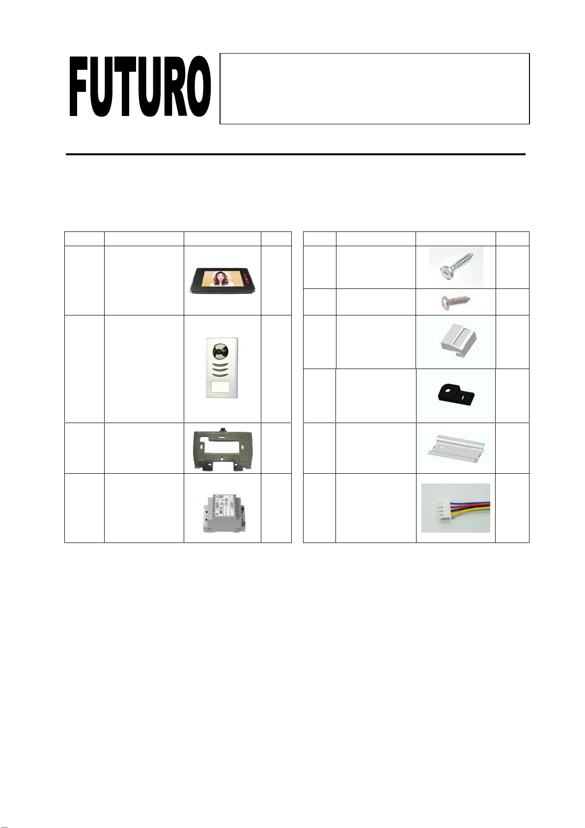
Indoor Unit(NVM-704-2)Specifications
Dimensions 235[W] ×120 [H] ×28 [D] mm
Weight 0.7Kg
Input Power DC14V (External Power Supply)
Power Consumption Idle mode : 2W Operating : MAX 14W
Connecting System 4 wires
Voice transmission Half duplex two way communication
Call sound Chime sound 2stroke
(When call button pushed)
Monitor to Camera 50M : 0.65mm2wire
100M : 1.0mm2wireMax. Distance & wiring Door Lock to Camera 20M : 1.0mm2wire
Video S/N Ratio 50dB
Audio S/N Ratio 40dB
Function 1. Monitor on, off / Talk 2. Door open
3. Camera 1, 2 select 4. Intercom
Aspect Material ABS
Display 7 inch LCD
Resolution More than 400 TV Lines
Monitor on time Stanby:30sec Talk off : 60sec
Users Control Brightness, Volume
Operating Temperature 0 ~ 40 ℃
Storage Temperature -20 ~ 60 ℃
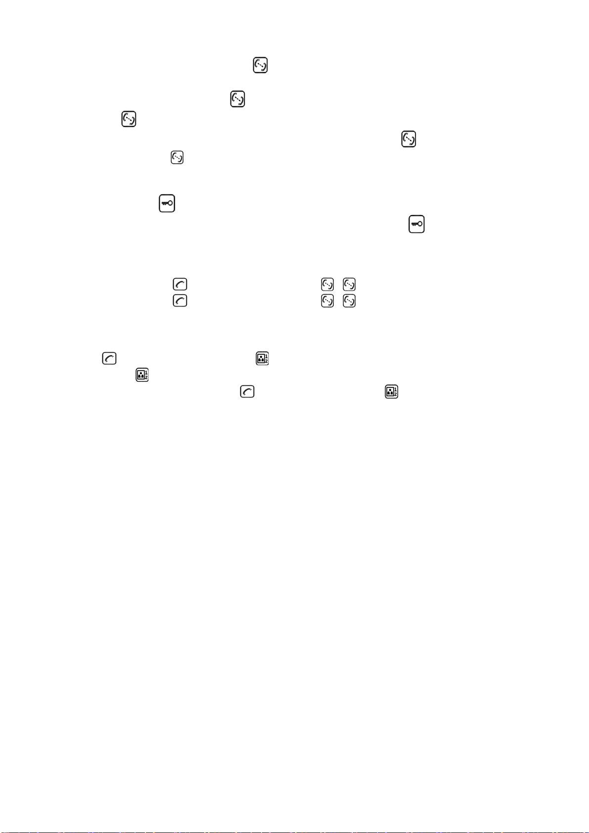
Outdoor Unit(NVC-3104)Specifications
Dimensions 92[W] ×198[H] ×21 [D] mm
Weight 0.4Kg
Input Power From monitor DC 12V
Power Consumption Max 3W
Aspect Material Aluminium
Wiring Monitor:4wires Door lock:2Wires
Image sensor 1/4 inch CCD
TV system CCIR
Resolution 380 TV Lines
Video output Composite video signal 1Vp-p at 75 ohm terminated
No. of pixels 270,000.pixels
Iris Electronic auto iris
Lighting White LED
Viewing Angle Diagonal:70˚horizontal:51˚vertical:41˚
Lens 3.6mm board lens
Min. Illumination 1Lux
Door lock 2 terminals with dry contact
Mounting type Surface mount
Operating Temperature -1 0˚C ~ 50˚C(14°F ~ 122°F)
Storage Temperature -20˚C ~ 60˚C

Page 3
Indoor unit
1. Monitor screen
2. Talk on/Talk off (Monitor off)
3. Door open button
4. Monitor on / (Camera 1, 2 select)
5. Intercom button
6. Volume control
7. Brightness control
Outdoor unit
1. Camera lens
2. White LEDs for night vision
3. Speaker
4. Call Button
5. Name Plate
6. Microphone

Page 4
Safety Instructions
1. Do not install near other electronic equipment such as computers, TV, video
recorder as this may cause radiated interference to the unit.
2. Do not disassemble the unit.
3. Do not spray water on the indoor unit. Do not keep the outdoor unit where it will be
exposed to extreme moisture.
4. Do not overload mains wall outlets or extension cords.
5. Do not drop or shock the unit.
6. Remove the power cord from the wall socket when unit is not used for long period.
7. Do not place any naked flames (e.g. lighted candles) on the apparatus.
8. Do not place objects filled with water (e.g. vases) on the apparatus.
9. Do not cover the ventilation holes with clothing, paper, curtains etc.
10. This apparatus is designed for moderate climates. Do not use in high humidity,
dusty or dirty areas.
11. To disconnect or isolate the unit, switch off at the socket or remove plug from wall
socket. Please ensure the plug and socket is easily accessible.
Warnings
1. Do not install the outdoor unit where it will be exposed to direct sunlight or any
strong reflected light. Avoid extremely bright locations for the indoor unit as the
monitor screen image will be adversely affected.
2. Do not install the outdoor unit where it will be subjected to extremes of dust or
moisture.
3. Do not install the outdoor unit where it will be exposed to rain.
4. Do not install near acid oxides, ammonia, or any harmful gas (it might cause
malfunction).
5. Do not install the outdoor unit in a location where the lens filter is likely to get
scratched or very dusty.
6. Check cables are connected correctly and camera unit is firmly installed.

Page 5
Assembly instructions
WIRING DIAGRAM
A) Cable connection
1. Connect the monitor to the camera with the cable according to the wiring diagram
below.
2. Carefully insert the wires to the terminal by pressing down the terminal flap with
any small tool taking care that the 2 bare wires do not touch.

Page 6
B) Installation height
1. Recommended installation height is approximately 140cm for monitor unit and
150cm for outdoor camera.
C) Installation of indoor monitor
1. Fix the wall mounting bracket in the best place by using 4 screws and plugs.
2. Carefully place the indoor monitor against the bracket and gently push down the
monitor so that the pins on the bracket engage in the slots on the rear of the
monitor.
Performance Settings
You can adjust the brightness, contrast and colour of the monitor when it is ON by
pressing the Performance menu button at the side of the monitor.
Press the menu button then the brightness, contract and colour indication will appear.
To select the indication by pressing the Up and Down buttons, then press the menu
button to confirm the selection and then press the Up and Down buttons to adjust.
Finally, press the menu button to confirm the setting.

Page 7
D) Installation of outdoor camera
Add the name to the nameplate
1) Release the button block from the panel and remove the cover (Fig. A & B)
2) The name plate is now accessible (Fig. C)
3) Mark your name on the plate (Fig. C)
4) Place the button block back to the panel (Fig. D)
A B C D
Mounting the camera
E F

Page 8
G H
1) Remove the front cover (Fig. E & F)
2) Mount the outdoor unit on the wall by using 2 mounting screws and wall plugs.
(Adjust the camera angle if necessary.)(Fig. G)
3) Replace the front cover and security it by replacing the 2 screws at the bottom of
the camera. (Fig. H)
Operating Instructions
1. Activation of units
When the call button on the outside camera unit is pressed, the indoor unit chime
rings and the visitor’s picture will appear on the indoor monitor. After the visitor is
visually identified, and you wish to talk with the visitor, press the button. The
unit will remain activated for approximately 60 seconds before it automatically shuts
off. To re-activate for continued conversation, press the button.
2. Activation of outside unit from monitor unit
a) Press the button of the indoor unit at any time and the outdoor camera will
be activated and show the outside view.
b) If you has installed two cameras, press this button to change from camera one
to another.
3. Working time
a) Call time: Approximately 30 seconds
The picture terminates automatically if indoor unit is not answered within
approximately 30 seconds after the call button of the outdoor camera unit is
pressed.
b) Talk time: Approximately 60 seconds
When monitor unit is called by the outdoor unit and the monitor is answered,
there is approximately 60 seconds of time available before the unit
automatically shuts off.
c) Monitor time: Approximately 30 seconds
When outside camera is activated from the inside, there is approximately 30
seconds of viewing time before the unit automatically shuts off.

Page 9
4. Activation of “Intercom” button
An intercom calling can be started by any indoor monitor.
When the intercom button on one indoor monitor is pressed,the intercom
button color will turn on blue, this will ring all monitors in a system,you can talk
with the one calling monitor by pressing the intercom button on the second
monitor, Press for shutting off. There is approximately 120 seconds of time
before the unit automatically shuts off.
5. Activation of button
If you want to open the door to let the caller in,just press the button on the
indoor monitor.
6. Mute on/Mute off
Mute on: push and hold on, then push . LED turns on green colour.
Mute off: push and hold on, then push .LED turns off green colour.
When the monitor’s status is Mute on, there will be no melody, while other
functions will be normal.
7. Change the moledy
push , at the same time push to activate this function.
Then press to choose target melody. There are 4 melodies available. To conifrm
melody you have chosen, push , at the same time push .

Page 10
Care and Maintenance
zDo not store in hot or cold areas. Extreme hot or cold temperatures can shorten
the life of electronic devices and can distort/melt certain plastics or may cause
malfunction.
zDropping can result in failure to operate. Circuit boards can crack and may not
survive the impact.
zDo not use or store in areas of high levels of dirt or dust. The electronics may be
contaminated. Any moving parts will wear prematurely.
zDo not use harsh chemicals, cleaning solvents or strong detergents. To clean,
wipe with a damp cloth from time to time.
Troubleshooting
No Problem Check point
1 No power
(no picture on monitor) ¾Is the power cable firmly inserted
into the terminal block?
2 Power is on, but no
picture on the monitor ¾Is the cable firmly connected
between the monitor and the
camera?
¾Is the polarity of wires correct
between the outdoor camera unit
and indoor monitor unit?
3
The picture is too dark
or white
¾Adjust brightness control
4 Chime sound is too low ¾Adjust the volume control
Environmental Protection
•Waste electrical products should not be disposed of with household
waste. Please recycle where facilities exist. Check with your Local
Authority or retailer for recycling advice.
This manual suits for next models
1
Table of contents