FuzzDog Dumb Lloyd V2 User manual

Dumb Lloyd V2
Dumble-ish drive with a
Tube Screamer base
Contents of this document are ©2014 Pedal Parts Ltd.
No reproduction permitted without the express written
permission of Pedal Parts Ltd. All rights reserved.

Schematic
R1 100R
R2 150K
R3 10K
R5 10K
R6 1K8
R7 10K
R8 1K
R9 10K
R10 10K
R11 220R
R12 100K
R13 10K
R14 10K
R15 100R
R16 10K
R17 1K
R18 1K
R22 1
RLED 2K2 (CLR)
C1 470n
C2 1u
C3 220n
C4 82p*
C5 220n***
C6 470n**
C7 47u elec
C8 2u2 elec
C9 100n
C10 220n
C11 22u elec
C12 100u elec
C14 100p
IC OPA2134
Q1,2 BC548B
D3 1N4001
D4 3mm Red LED
TONE 20-25KB
DRIVE 1 A
LEVEL 100KA
ACCENT 20-25KB
BO
*It’s very unlikely you’d hear any difference if you want to use a
100pf cap for C4.
**C6 has been included in case you want to make the ‘Special’
version. If not, leave it out. See overleaf.
***C5 was left as an electrolytic - a hangover from the Tube Screamer schematic. An electrolytic
will work fine, but you can use a non-polarised cap if you can get one in 2.5mm pitch.
There’s nothing particularly special about the IC or the transistors. Go ahead and try any other
dual op-amps and BJTs. Note that the pinout of the BC548B is opposite to 2N3904/2N5088 etc.

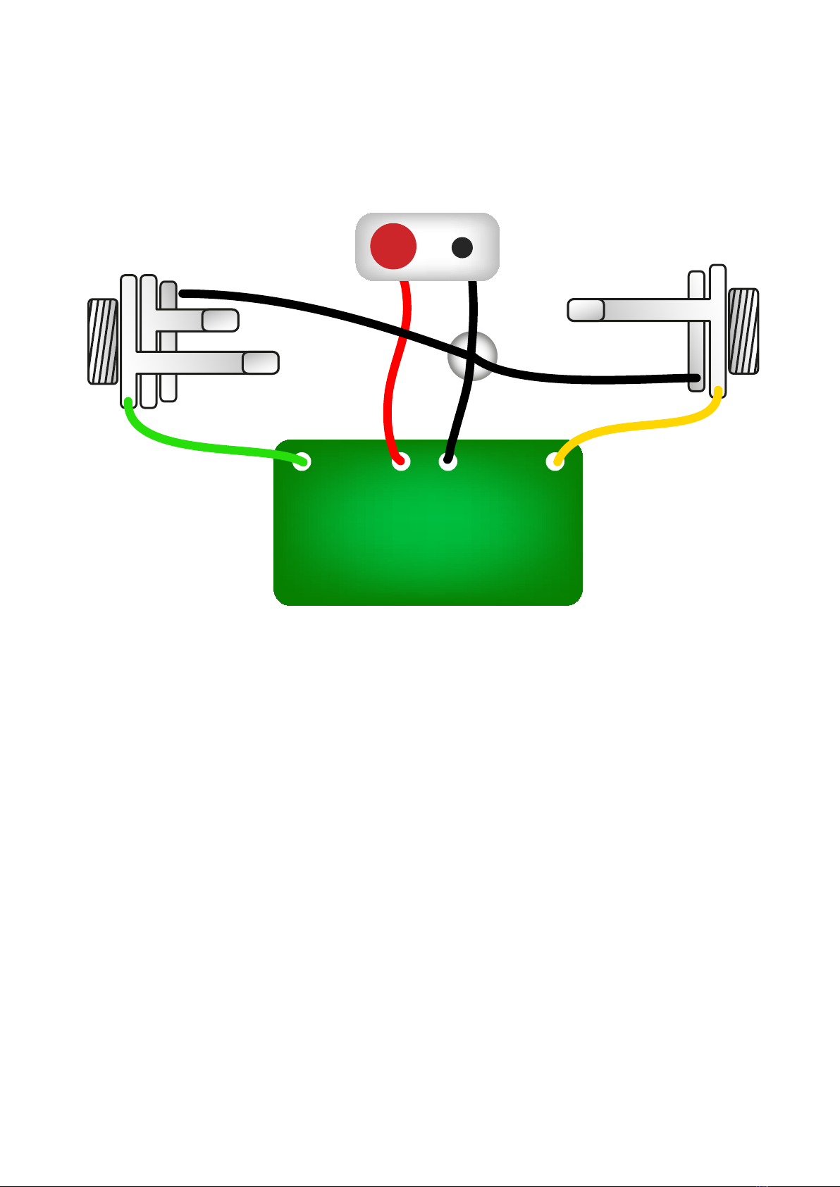
The power and signal pads
on the PCB conform to the
FuzzDog Direct Connection
format, so can be paired
with the appropriate
daughterboard for quick and
easy offboard wiring. Check
the separate daughterboard
document for details.
Be very careful when
soldering the transistors
and diodes. They’re very
sensitive to heat. You should
use some kind of heat sink
(crocodile clip or reverse
action tweezers) on each leg as you solder them. Keep exposure to heat to a minimum (under 2
seconds). You should really use a socket for the IC. If not, be extra careful not to overheat.
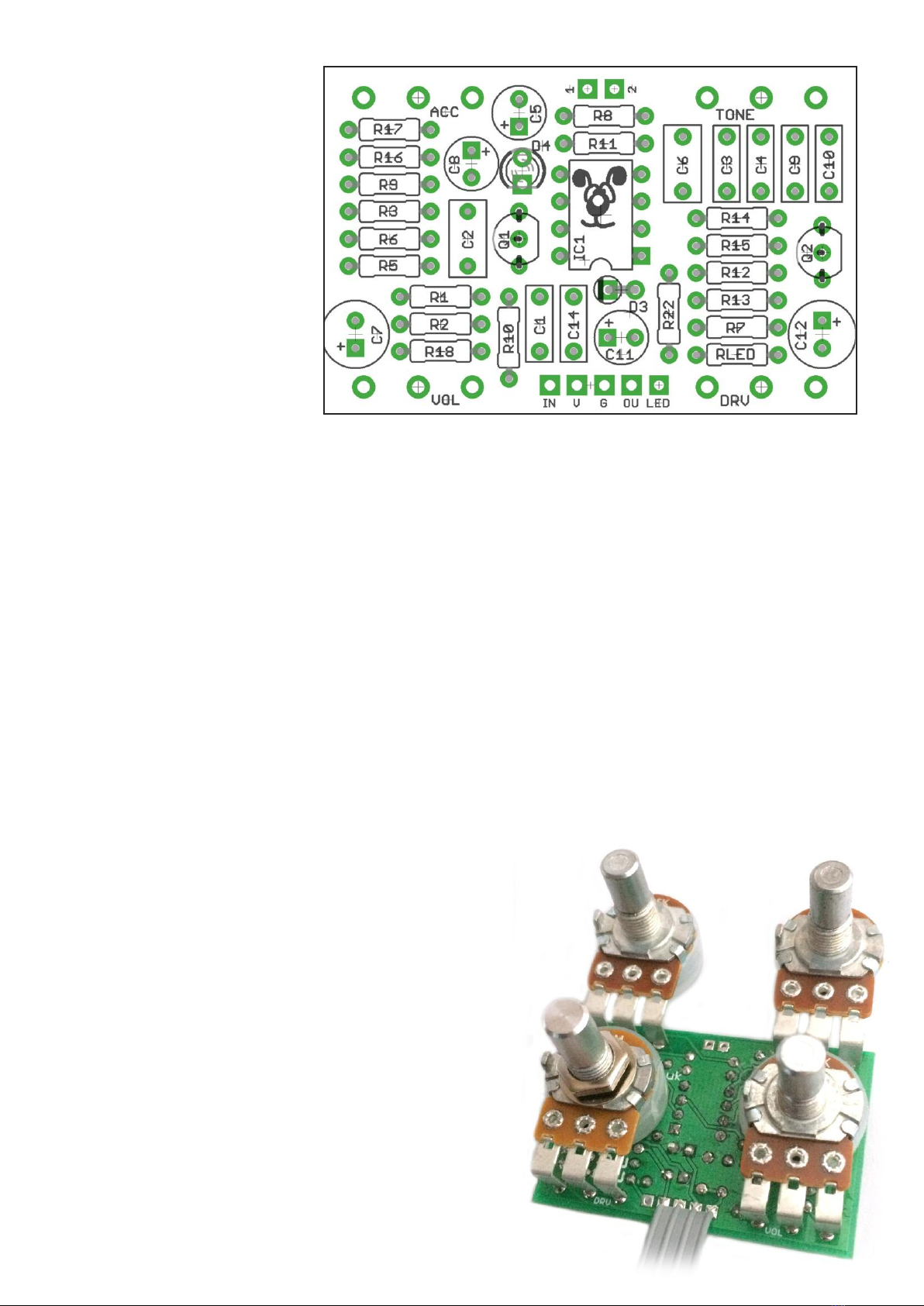
Snap the small metal tag off the pots so they can be mounted flush in the box.
Positive (anode) legs of the electrolytic caps go to the square pads. C7 and C12 can be laid flat over
the adjacent resistors as shown in the cover image to give you extra clearance in the enclosure.
Negative (cathode) legs of the diodes go to the square pads. That’s the short one on the LED.
You should solder all other board-mounted components before you solder the pots. Once they’re in
place you’ll have no access to much of the board. ake sure your pots all line up nicely. The best
way to do that is to solder a single pin of each pot in place then melt and adjust if necessary before
soldering in the other two pins. If your pots don’t have protective plastic jackets ensure you leave a
decent gap between the pot body and the PCB otherwise you risk shorting out the circuit.
SPECIAL EDITION - JAZZ or ROCK???
If you want to waste a capacitor and a toggle switch,
go ahead and build the Deluxe version. Simply include
C6 in your build, and add a toggle switch to pads 1
and 2, above R8 on the PCB. This can be a SPST. It
just takes C6 in and out of the circuit.
PCB Layout ©2015 Pedal Parts Ltd.

Test the board!
U DER O CIRCUMSTA CES will troubleshooting help
be offered if you have skipped this stage. o exceptions.
Once you’ve finished the circuit it makes sense to test is before
starting on the switch and LED wiring. It’ll cut down
troubleshooting time in the long run. If the circuit works at this
stage, but it doesn’t once you wire up the switch - guess what?
You’ve probably made a mistake with the switch.
Solder some nice, long lengths of wire to the board connections for
9V, G D, I and OUT. Connect I and OUT to the jacks as shown.
Connect all the G Ds together (twist them up and add a small
amount of solder to tack it). Connect the battery + lead to the 9V
wire, same method. Plug in. Go!
If it works, crack on and do your switch wiring. If not... aw man.
At least you know the problem is with the circuit. Find out why,
get it working, THE worry about the switch etc.
BATTERY
IN OUT
Your nice, new circuit board
INCLUDING WIRED POTS!!!!
IN 9V GND OUT

Wire it up (if using a daughterboard please refer to the relevant document)
Wiring shown above will disconnect the battery when you remove the jack
plug from the input, and also when a DC plug is inserted.
The Board G D connections don’t all have to directly attach to the board. You
can run a couple of wires from the DC connector, one to the board, another to
the I jack, then daisy chain that over to the OUT jack.
It doesn’t matter how they all connect, as long as they do.
This circuit is standard, egative G D. Your power supply should be Tip
egative / Sleeve Positive. That’s the same as your standard pedals (Boss etc),
and you can safely daisy-chain your supply to this pedal.
PedalParts.co.uk
L
E
D
BOARD
OUT
BOARD
9V
BOARD
GND
BOARD
GND
BOARD
GND
BOARD
INPUT
BATTERY
+
IN
OUT
L
E
D
BOARD
GND
BOARD
LED+
+

This template is a rough guide only. You should ensure correct marking of your
enclosure before drilling. You use this template at your own risk.
Pedal Parts Ltd can accept no responsibility for incorrect drilling of enclosures.
FuzzDog.co.uk
Drilling template
Hammond 1590B
60 x 111 x 31mm
Recommended drill sizes:
Pots 7mm
Jacks 10mm
Footswitch 12mm
DC Socket 12mm
32mm
27mm
It’s a good idea to drill
the holes for the pots
1mm bigger to give
yourself some wiggle
room, unless you’re a
drill ninja.
Table of contents
Other FuzzDog Motherboard manuals