en
ÚInstallation instructions
Important notes
Read these instructions carefully and keep them in a safe place.
Safety during use can only be ensured if the appliance is fitted
correctly according to these installation instructions. The
installer is responsible for ensuring that the appliance operates
perfectly at the point of installation.
Use approved flexible gas tubing bearing EMSD approval
marking (such as EMSD APPROVAL GTXXXX) for connection to
appliance, or other approval methods by EMSD.
Before carrying out any type of work, turn off the electricity and
gas supply.
For installation, currently applicable building regulations and the
regulations of local electricity and gas suppliers must be
observed.
Depending on the country, the gas governor (MAXITROL with
model no. RV47LSM-44-0013) comes with the hob.
For conversion to another type of gas, please call the after-sales
service.
: Risk of gas escape!
After connecting the appliance to the gas supply, always check
the connection for leak tightness. The manufacturer accepts no
responsibility for the escape of gas from a gas connection
which has been previously tampered with.
Ensure sufficient air exchange in the room where the
appliance is installed. Up to 11 kW total output:
■Minimum volume of the room where appliance is installed:
20 m³
■A door leading to the open air or a window which can be
opened.
Up to 18 kW total output:
■Minimum volume of the room where appliance is installed:
2 m³ per kW total output.
■A door leading to the open air or a window which can be
opened.
■An extraction hood into the open air. Minimum displacement
volume of extraction hood: 15 m³/h per kW total output.
The installation system must incorporate an all-pin isolating
switch with a contact opening of at least 3 mm, or the appliance
should be connected to the mains via a safety plug. The plug
must remain accessible after installation is complete.
Specifications on the rating plate showing voltage, type of gas
and gas pressure must agree with the local mains connection
conditions.
Do not kink or trap the mains connection cable.
This appliance corresponds to appliance class 3 (for installation
in a kitchen unit). It must be fitted according to the installation
drawing. The wall behind the appliance must be made of non-
flammable material.
This appliance is not intended for operation with an external
timer or an external remote control.
Do not install this appliance on boats or in vehicles.
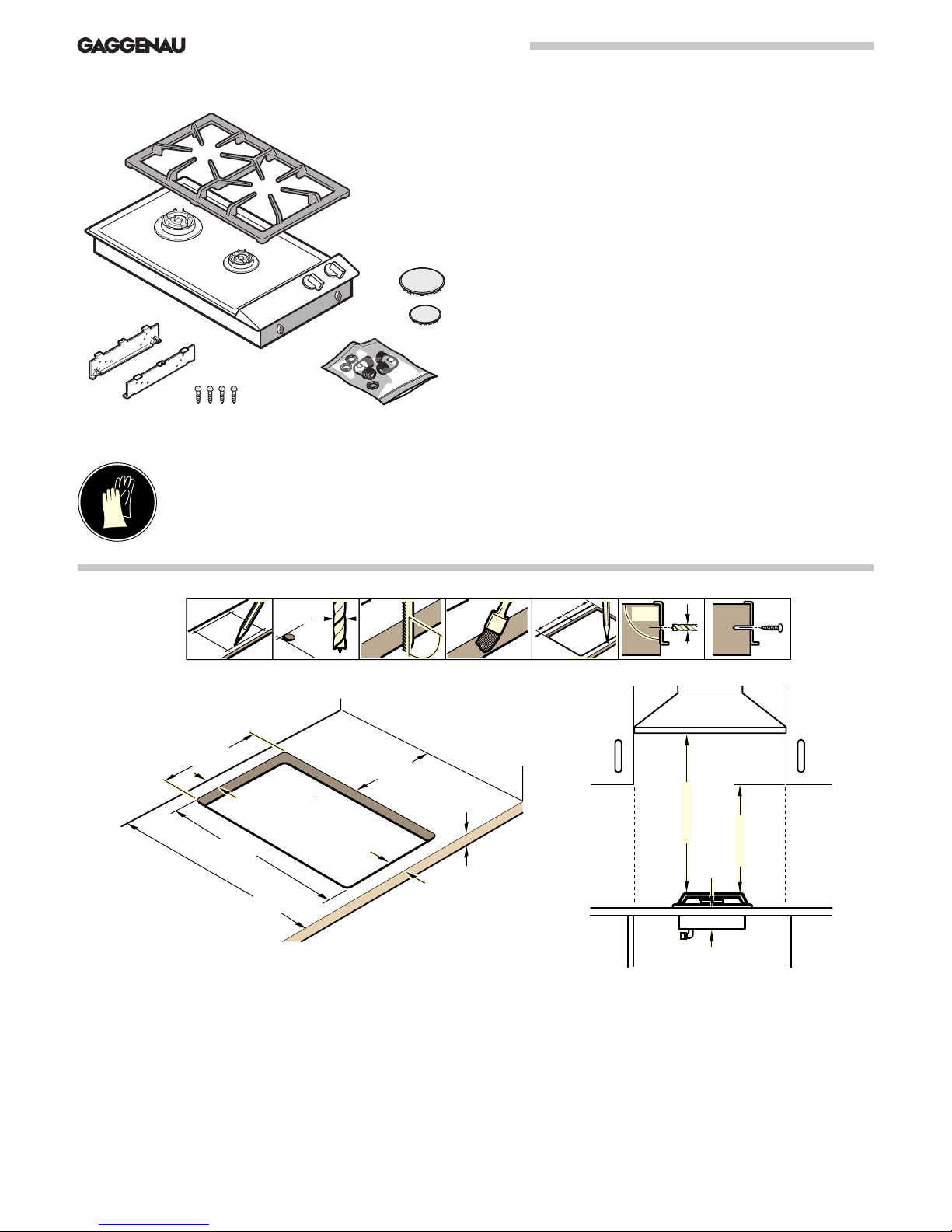
Preparing the furniture
The surrounding kitchen unit must be heat-resistant to at least
90 °C. The stability of the unit must be maintained after
producing the cut-out.
Produce the cut-out for one or several Vario appliances.
Proceed as shown in the installation sketch. The angle between
the cut surface and the worktop must be 90°.
After producing the cut-out, remove the shavings. Seal the cut
surfaces to make them heat-resistant.
Observe a minimum clearance between the appliance housing
and parts of the unit of 10 mm.
When fitting several Vario appliances: allow for the additional
space required for the connecting strip VV 200. Appliances can
also be fitted in individual recesses, if a minimum clearance of
40 mm between the appliances is observed.
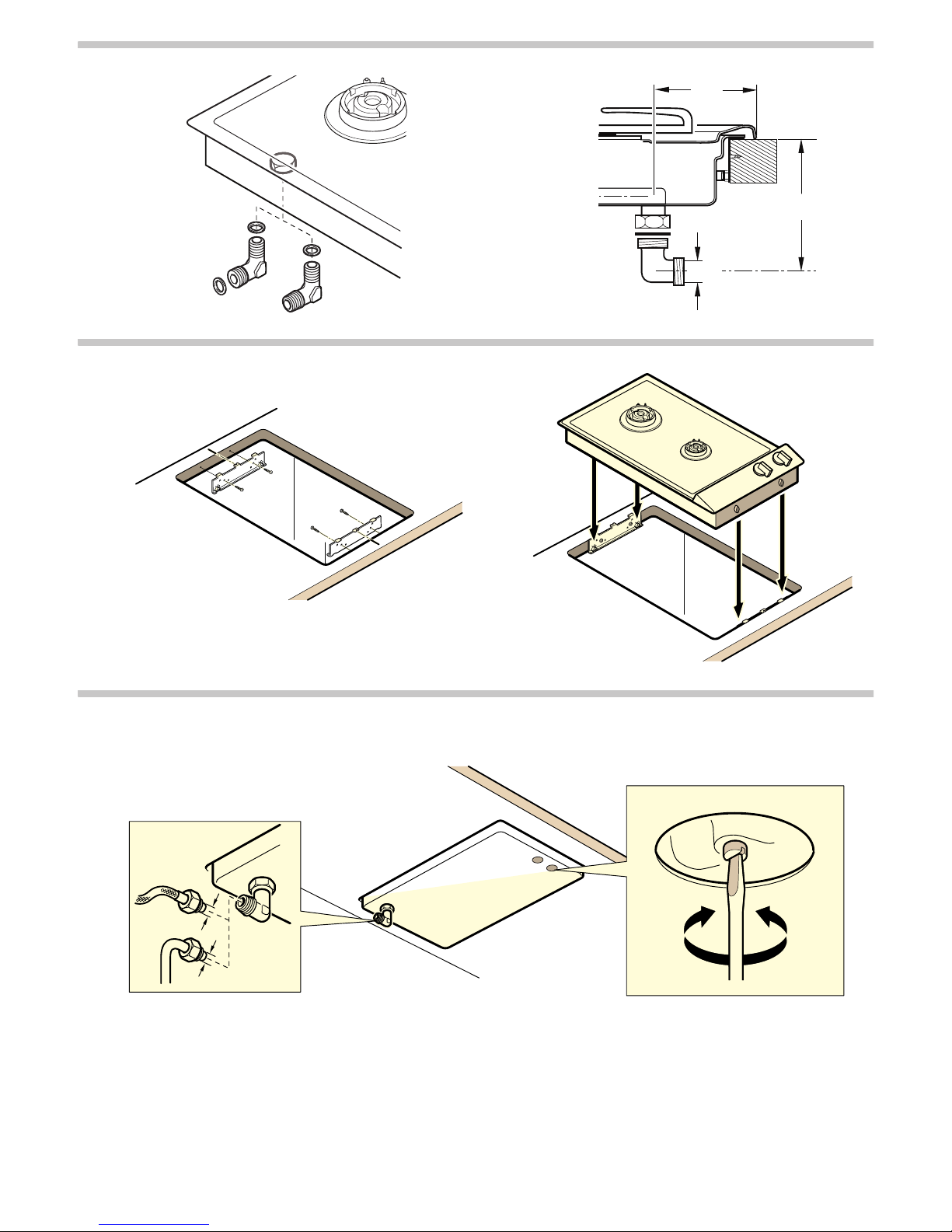
Fitting the appliance
1. Mark the centre of the recess exactly. Fit the mounting rails to
the front and rear of the recess. Make sure the lugs of the
mounting rails lie on the worktop. The centre marking on the
mounting rails must be precisely flush with the centre marking
of the recess.
Note: when fitting the appliance in a stone worktop glue on the
mounting rails with a temperature-resistant two-component
adhesive (metal on stone).
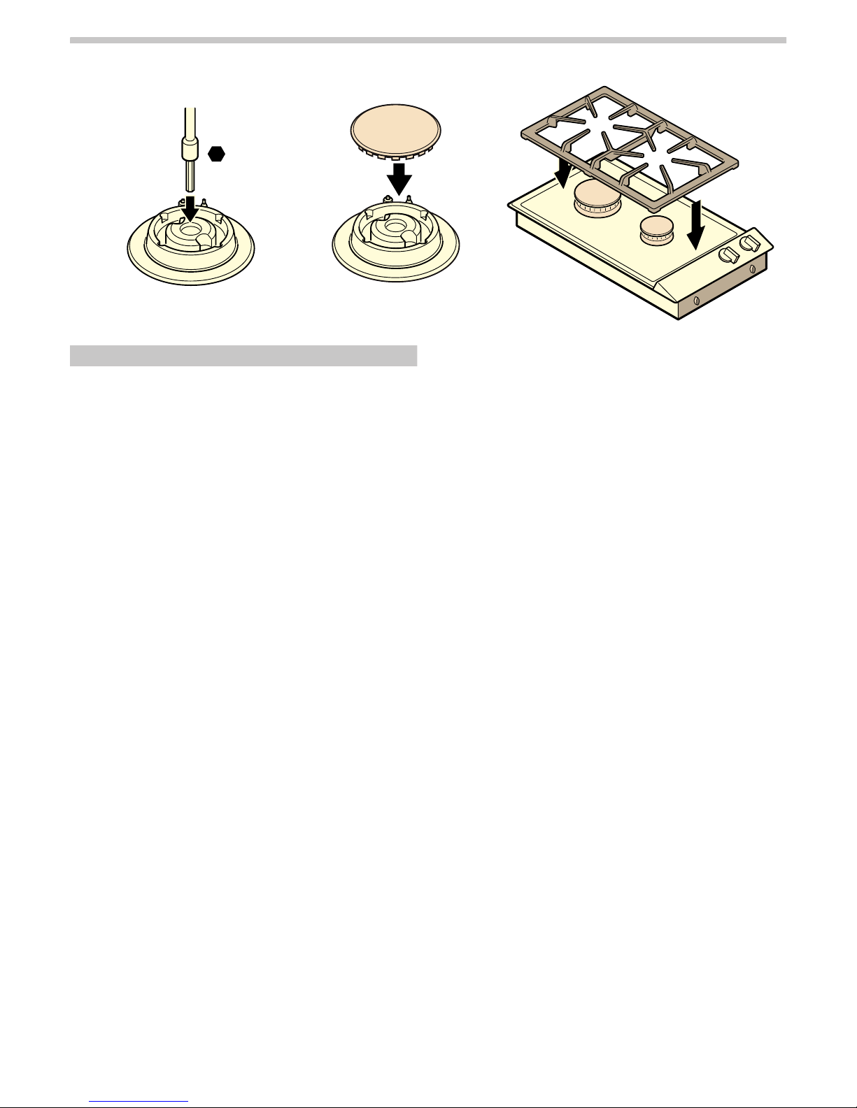
2. For combination with the appliance cover VD 201: secure the
appliance cover on the appliance before installation (refer to
the installation manual of VD 201).
3. Lower the appliance into the cut-out. The snap-in pins on the
appliance must lie exactly on the catch springs. Firmly press
the appliance into the cut-out. The pins on the appliance must
snap into the catch springs.
Removing the appliance
Disconnect the appliance from the power and the gas supply.
Push out the appliance from below.
Caution!
Risk of damage! Do not lever out the appliance from above.
Gas connection
The gas connection must be located in a position where the
stop tap is accessible.
According to the Hong Kong Gas Safety Regulations, any gas
installation works, including appliance and flexible hose
installations shall be undertaken by registered gas installers.
The installers shall register for appropriate class and be
employed by registered gas contractor.
Using one of the R½'' (for appliance side) connection elbows
provided, connect the appliance with the associated gasket to a
fixed connection pipe or a gas safety hose. If the gas safety
hose is not (or only partly) made of metal, the ambient
temperature must not exceed 70°K. In the case of a gas safety
hose made entirely of metal, the permissible ambient
temperature is 115°K. The gas safety hose must be routed so
that it does not come into contact with moving parts of the
kitchen unit (e.g. drawers).