Galanz GL1SS24TBD User manual

nce,
using
rom
ted
ore
e
e
n it is
at
e for
cturing
ng.
moke
©2019 Galanz Americas Limited Company
Model#
GL1SS24TBD GL1SS30TBD
Gas Cooktop User’s Manual
Thank you for purchasing a Galanz product. Please read this manual carefully for correct usage and safety,
and keep for future reference. For service, support and warranty information, call 800-562-0738.
@2019 Galanz Americas Limited Company.

©2019 Galanz Americas Limited Company
Thank you for purchasing a G alanz product. Please read this manual carefully for correct usage and safety,
and keep for future reference. For service, s upport and warranty information, call 800-562- 0738.
FPO
CONTENT
CONTENT
nce,
using
rom
ted
ore
e
e
n it is
at
e for
cturing
ng.
moke
1
INSTALLATION
USE AND CARE
SAFETY NOTICE................................................................................................................ 2
RANGE HOOD OPERATIONS.............................................................................................18
TROUBLESHOOTING.........................................................................................................19
ELECTRIC SCHEMATIC.....................................................................................................21
WARRANTY
COVERAGE & EXCEPTIONS..............................................................................................24
DISCLAIMER......................................................................................................................25
CONTACT INFORMATION................................................................................................. 25
MAINTENANCE
CLEANING, REPLACING FILTER & LIGHTBULB................................................................ 22
SPECIFICATIONS....................................................................................................................... 4
PARTS SUPPLIED...................................................................................................................... 5
TOOLS REQUIRED.....................................................................................................................5
VENTING REQUIREMENTS........................................................................................................ 6
VENTING METHODS.................................................................................................................. 7
HEIGHT CLEARANCES & DUCT SIZE CALCULATOR................................................................ 8
CHARCOAL FILTER INSTALLATION & ELECTRICAL REQUIREMENTS......................................8
PREPARATION...........................................................................................................................10
INSTALLATION OVERVIEW........................................................................................................ 12
INSTALLATION..... .....................................................................................................................13

Thank you for purchasing a G alanz product. Please read this manual carefully for correct usage and safety,
and keep for future reference. For service, s upport and warranty information, call 800-562- 0738.
FPO
INSTALLATION
INSTALLATION
©2019 Galanz Americas Limited Company
2
READ ALL INSTRUCTIONS BEFORE INSTALLING
AND OPERATING THIS APPLIANCE
WARNING
Your safety and the safety of others is very important. We have
provided many important safety messages in this manual and on
your appliance. Always read and obey all safety messages. All safety
messages will tell you what the potential hazard is, tell you how to
reduce the chance of injury, and tell you what can happen if the
instructions are not followed.
This is the safety alert symbol. This symbol alerts you to potential
hazards that can hurt you and others. All safety messages will follow
the safety alert symbol “/tv’ and the word “WARNING”.
Excessive Weight Require three or more persons to move and install
this range hood. Spinal or other bodily injuries could occur if it is not.
WARNING
Light bulb become extremely hot when turned on. DO NOT touch
bulb until switched off and cooled. Touching hot bulbs could cause
serious burns.
WARNING
Severe Injury
Rotating fan can cause severe injury. Stay clear of fan when power is
present.
WARNING
Excessive Weight Require three or more persons to move and install
this range hood. Spinal or other bodily injuries could occur if it is not.
WARNING
Hazard of electrical shock!
Hazard of Burns!
Do not perform service on an electrically live system.
Disconnect the main electrical supply before servicing this
device. Touching electrical connectors or other exposed
electrical circuity inside this range hood when they energized
could result in death, serious bodily injury, or property
damage.
IMPORTANT SAFETY NOTICE

Thank you for purchasing a G alanz product. Please read this manual c arefully for correct usage and s afety,
and keep for future reference. For service, s upport and warranty information, call 800-562- 0738.
FPO
INSTALLATION
INSTALLATION
3
TO REDUCE THE RISK OF A STOVE TOP GREASE FIRE:
Ducted fans MUST always be vented to the outdoors.
DO NOT vent exhaust into spaces between walls, crawl spaces,
ceiling, attics or garages.
Any old duct work should be cleaned or replaced if necessary to
avoid the possibility of a grease fire. Check all joints on duct work
to insure proper connection and all joints should be properly
taped.
Use only metal ductwork and this unit MUST be grounded.
Before servicing or cleaning unit, switch power OFF at service
panel and lock service panel toprevent power from being
switched ON accidentally.
When cutting or drilling into wall or ceiling, be careful not to
damage electrical wiring or other hidden utilities.
All electrical wiring must be properly installed, insulated and
grounded.
Use this unit only in the manner intended by the manufacturer. If
you have questions, contact the vendor.
DO NOT touch the bottom side of the range hood directly after
usage because it may be hot. Wait until it has cooled.
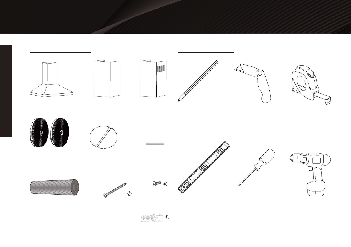
Make sure to inspect shipment and it’s contents as soon
shipment is received.
Plug in and test range hood and all its functions, (refer to Range
Hood Operations, Page 15), directly after receiving shipment,
and before scheduling an installer.
Clean grease laden surfaces frequently.
Clean ventilating fan frequently.
Keep all surfaces clean from grease or oil build up.
Grease should not be allowed to accumulate on fan, baffle, spaces,
filter, grease tunnel and oil container.
Always turn range hood ON when cooking at high heat or when
cooking flaming foods. Use high settings on cooking range only
when necessary.
Never leave burners or cooktop at high settings unattended. Boil
overs cause smoking and greasy spillovers that may ignite. Heat oils
slowly on low or medium settings.
Always use appropriate cookware and utensils size.
Always use cookware appropriate for the size of the surface
element.
TO REDUCE THE RISK OF INJURY TO PERSONS IN THE EVENT
OF A STOVE TOP GREASE FIRE:
SMOTHER FLAMES with a close-fitting lid, cookie sheet, or metal
tray, then turn OFF the burner. BE CAREFUL TO PREVENT BURNS.
NEVER PICK UP A FLAMING PAN-you may be burned.
KEEP FLAMMABLE OR COMBUSTIBLE MATERIAL AWAY FROM
FLAMES. If the flames DO NOT go out immediately, EVACUATE
AND CALL THE FIRE DEPARTMENT or dial your local emergency
service immediately.
DO NOT USE WATER, including wet dishcloths or towels — a
violent steam explosion may result.

Thank you for purchasing a Galanz product. Please read this manual carefully for correct usage and safety,
and keep for future reference. For service, support and warranty information, call 800-562-0738.
FPO
INSTALLATION
INSTALLATION
©2019 Galanz Americas Limited Company
nce,
using
rom
ted
ore
e
e
n it is
at
e for
cturing
ng.
moke
4
Use an extinguisher ONLY if:
Extinguish any open flame.
DO NOT turn on the range hood fan or any type of ventilator.
DO NOT turn on the lights or any type of appliance.
Open all doors and windows to disperse the gas. If you still smell
gas, call the gas company and fire department, or dial your local
emergency service immediately.
You know you have a Class A, B, C extinguisher, and you already
know how to operate it.
The fire is small and contained in the area where it is started.
The fire department is being called.
You can fight the fire while maintaining a safe exit path.
TO REDUCE THE RISK OF INJURY TO PERSONS IN THE EVENT
OF A GAS LEAKS:
SPECIFICATIONS
Body Material
Overall Voltage
Maximum Power Usage
* Subject to change without notice, please contact your local
reseller for details.
Ducting / Venting
Protections
Filtration Type
Stainless Steel, Brushed Finish
115V/60HZ
88W
6 inches, Round, Top Venting
Electrical Short Fuse
Stainless Steel Baffle Filter

INSTALLATION
Thank you for purchasing a G alanz product. Please read this manual carefully for correct usage and safety,
and keep for future reference. For service, s upport and warranty information, call 800-562- 0738.
FPO
INSTALLATION
©2019 Galanz Americas Limited Company
nce,
using
rom
ted
ore
e
e
n it is
at
e for
cturing
ng.
moke
5
PARTS SUPPLIED TOOLS NEEDED
Range Hood Lower Chimney Upper Chimney
Marker or Pencil Utility Knife Measuring Tape
Level Flat & Phillips
Screwdrivers
Powered Drill
Charcoal Filter
(Sold Seperately)
Flexible Duct Tube
Range Hood Hook
Draft Damper Flaps Chimney
Mounting Bracket
Qty: 2 PCS
Qty: 9 PCS
Qty: 9 PCS

INSTALLATION
Thank you for purchasing a G alanz product. P leas e read this manual c arefully for correc t usage and s afety,
and keep for future reference. For service, s upport and warranty information, call 800-562- 0738.
FPO
INSTALLATION
©2019 Galanz Americas Limited Company
6
Vent system must terminate to the outside (roof orside wall).
DO NOT terminate the vent system in an attic orother enclosed
area.
DO NOT use 4”(10 cm) laundry-type wall caps.
Use metal/aluminum ducting only. Rigidmetal/aluminum ducting
is recommended.
Always keep the duct clean to ensure proper airflow.
Calculate the following figures before installation:
A distance of 26” to 30” is recommended betweenstove top and
the bottom of range hood.
26" is the lowest recommended for safe operation;30" is only
recommended for efficient operation, butcan be mounted higher.
It is recommended that the range hood be ventedvertically
through the roof through 6" (15 cm) orlarger round metal/alumi-
num vent work.
The size of the vent should be uniform.
Use no more than three 90° elbows.
For best results, attempt to make a minimum of24" (61 cm) of
straight vent between the elbows ifmore than one elbow is used.
DO NOT install two elbows together.
The length of vent system and number of elbowsshould be kept
to a minimum to provide efficientperformance.
The vent system must have a damper.If roof or wall cap already
has a damper, DO NOT use the supplied damper (if applicable).
Use duct tape or equivalent to seal all joints in thevent system.
Use caulking to seal exterior wall or roofopening around the cap.
2 Due to different ceiling height configurationsf recommended
height may not be applicable.
1. Distance from the floor to the ceiling. *(less than108").
2.Distance between the floor to thecountertop/stove.
(Recommend 26ft to about30").
3.Distance between the countertop/stove to therange hood.
(Recommended26" to -30").
4.Height of range hood body and chimney coverscombined.
(Extension available1 2)
For the most efficient & quiet operation:
VENTING REQUIREMENTS

7
Thank you for purchasing a G alanz product. Please read this manual c arefully for correct usage and s afety,
and keep for future reference. For service, s upport and warranty information, call 800-562- 0738.
FPO
INSTALLATION
INSTALLATION
IMPORTANT
This range hood is factory set for venting through the roof or wall.
Vent work can terminate either through the roof or wall. To vent
through a wall, a 90° elbow is needed.
NEVER exhaust air or terminate duct work into spaces between
walls, crawl spaces, ceiling, attics orgarages. All exhaust must be
ducted to the outside.
Use metal/aluminum duct work only.
Fasten all connections with sheet metal screws and tape all joints
with certified duct tape or equivalent.
Use caulking to seal exterior wall or roof opening around the cap.
VENTING REQUIREMENTS VENTING METHODS
Horizontal Wall Venting
Option 1: Option 2:
Vertical Roof Venting

Thank you for purchasing a G alanz product. P leas e read this manual c arefully for correc t usage and s afety,
and keep for future reference. For service, s upport and warranty information, call 800-562- 0738.
FPO
INSTALLATION
INSTALLATION
©2019 Galanz Americas Limited Company
8
A minimum of 6" round (standard for this range hood) must be used
to maintain maximum airflow efficiency.
A flexible 6" round duct is provided for convenience and for use in
difficult installations, however alwaysattempt to use a smooth
metal/aluminum rigid type of ducting to maximize airflow efficiency.
ALWAYS, when possible, reduce the number or transitions and
turns. If long duct run is required, increaseduct size to 7" or 8". If a
reducer is used, install a long reducer instead of a pancake reducer.
Any reductionsof duct size will restrict and decrease airflow; to
maximize airflow flow efficiency place any reducers furthestaway
from any bends or transitions.
If turns or transitions are required, install them as evenly distanced as
possible, and as far away from therange hood as possible.
Please use the Duct Size Upgrade Calculator below to compute the
total available duct run when usingelbows, transitions and caps.
It is important to install the hood at the proper mounting height.
Hoods mounted too low is considered unsafeand could result in
heat damage and fire hazard; while hoods mounted too high are
harder to reach and willloose general effectiveness.
Minimum mount height between stove top to hood bottom should
be no less than 26''. Any less isconsidered unsafe and not recom-
mended.
Maximum mount height between stove top to hood bottom can be
higher than 30" is recommended to be thebest efficiency. (Extension
available*)
If available, also refer to stove top manufacturer's height clearance
requirements and recommended hoodmounting height above range.
Round ■6” minimum
Minimum duct size recommended is 6” round. Maximum duct
length recommend is 50 ft. Any duct length over 50 ft is
recommended to use a larger diameter duct size.
Survey the installation application and record the estimated
length of ducting required or used for that application. Record
the number of bends, angle of bends, and/or any transitional
pieces used. Each bend or transition will reduce air flow and
reduce the recommended duct length.
*Due to different ceiling height configurations, recommended height may
not be applicable.
Height & Clearance
minimumDuct Size Upgrade Calculator
Duct Deductions:
Each 90° bend 9 ft
Each 45° bend 5 ft
Each 6” to 3 1/4” x 10” transition 7 ft
Side wall cap with damper 1 ft
Roof Side wall cap with damper 1 ft
IMPORTANT
Minimum Duct Size:

Thank you for purchasing a G alanz product. Please read this manual c arefully for correct usage and s afety,
and keep for future reference. For service, s upport and warranty information, call 800-562- 0738.
FPO
9
INSTALLATION
INSTALLATION
To contact a qualified electrical installer.
To assure that the electrical installation is adequate and in
conformance with National Electrical Code,ANSI/NFPA 70 —
latest edition*, or CSA Standards C22.1-94, Canadian Electrical
Code, Part 1 and C22. 2No. 0-M91 - latest edition** and all local
codes and ordinances.
Provide a circuit protected power service; preferably a Ground
Fault Circuit Interrupter (f,G.F.C.I.f,): 120-volt,60 Hz, AC, with at
least 2-amps of available service.
Enlist a qualified electrician to ensure the range hood and
electrical lines are adequately grounded andproperly protected.
NEVER electrically ground to a gas pipe.
The range hood should be connected with a circuit breaker
protected power service.
Wire sizes (copper wire only) and connections must conform with the
rating of the appliance as specified on the model/serial rating label.
Wire sizes must conform to the requirements of the National Electrical
Code ANSI/NFPA 70 — latest edition*, or CSA Standards C22.1-94,
Canadian Electrical Code Part 1 and C22. 2 No. 0-M91 - latest
edition** and all local codes and ordinances. A U.L. - or C.S.A. - listed
conduit connector must beprovided at each end of the power supply
cable (at the range hood and at the junction box).
(1)90o bend, (1) 31/,x 10” transition, (2) 45° bends,(1)sidewall
cap with damper (with factory dampernot installed)
-9ft + -7ft + -5ft + -5ft + -1ft = -27ft
Deduct 27 ft from 50 ft, giving you 23 ft of available straight
ducting before it is recommended to upgrade your ducting size.
Remove grease filters from the hood.
Position the charcoal filters onto both side of the motor housing,
aligning the mounting points, turn until itlocks. Re-install baffle
filters.
Charcoal filters must be replaced after 120 hours of use (or
approximately every 2 to 3 months based on theaverage of 1 to
2 hours of daily cooking time). Available at your local resellers.
It is the customer’s responsibility:
1.
2.
3.
IMPORTANT: Observe all governing ordinances and local codes.
(Please consult with a qualified electrician for any electrical wiring)
IMPORTANT: Save this Installation Guide for future reference
and/or electrical inspector use.
Charcoal Filter Installation
Electrical Requirements
Duct Deduction Calculation Example:
NOTE:
OPTIONAL CHARCOAL FILTERS (SOLD SEPERATELY)

Thank you for purchasing a G alanz product. P leas e read this manual c arefully for correc t usage and s afety,
and keep for future reference. For service, s upport and warranty information, call 800-562- 0738.
FPO
INSTALLATION
10
INSTALLATION
Copies of the standards listed may be obtained from:
*National Fire Protection Association
Batterymarch Park
Quincy, Massachusetts 02269
** CSA International
8501 East Pleasant Valley Road
Cleveland, Ohio 44131-5575
Familiarize yourself with the controls of the range hood by
readingthrough Range Hood Operations, Page 15.
Place the range hood on a flat, stable surface. Connect the
rangehood to a designated standard outlet (please refer the
product labelfor the suitable voltage of this unit) and turn on the
range hood.Verify all operations of the range hood by referring
to Range HoodOperations, Page 15.
Place all supplied parts and required hardware on a flat, stable
surface and verify the presence of all PartsSupplied listed on
Page 4.
Carefully remove the white plastic protective coat from the
chimney covers and range hood.
Determine whether your household ducting has a draft damper
system; only 1 draft damper system isrecommended for proper
efficiency.
Determine if you will be using the draft damper system on the
range hood. Install them onto the range hoodbefore starting the
installation. If you are using a draft damper system within the
household ducting, thedraft dampers do not need to be used
on the range hood.
Excessive Weight Require three or more persons to move and
install this range hood. Spinal or other bodily injuries could
occur if it is not followed.
1.
2.
3.
4.
5.
6.
WARNING
Preparation
Advanced Preparations:

Thank you for purchasing a G alanz product. Please read this manual c arefully for correct usage and s afety,
and keep for future reference. For service, s upport and warranty information, call 800-562- 0738.
FPO
INSTALLATION
11
INSTALLATION
Severe Injury
Rotating fan can cause severe injury. Stay clear of fan when
power is present.
WARNING
Determine and mark the center line on the wall where the range
hood will be installed. Make sure there isproper clearance within
the ceiling or wall for exhaust vent.
Due to the weight and size of this unit, please make sure that
the support system or framework being used isstable and
secure in the wall or ceiling.
Put a thick, protective covering over counter top, cook top or
range to protect from damage or dirt. Removeany hazardous
objects around the area when installing.
Mark the locations of the support mounting bracket holes,
ducting cutout (if used) and power supply cablecutout on the
wall or ceiling behind the chimney. Use drill and saber saw or
keyhole saw to cut openings forpower supply cable and ducting
(see Venting Requirements and Electrical Requirements, Pages
6 & 9 ).
If venting to the outside install vent system (see Venting
Methods, Page 7). Use caulking to seal exterior wallor roof
openings.
Disconnect main electrical supply, prepare and run electrical
wiring through ceiling or wall. Install a poweroutlet within
reaching distance of the range hood assembly. DO NOT restore
power until installation iscompleted.
Disconnect power cord, remove the baffle filter by pressing on
the latch toward the direction of solid arrowwhile holding the
metal handle, gently pull the aluminum filter toward the direction
of dashed arrow as shownin Figure 1.
Set aside the baffle filters and grease cup until the range hood is
properly installed.
If the range hood comes with a glass canopy and has not already
been mounted to the hood, loosen the fourcanopy screws and
washers from the hood top, carefully place the canopy on the hood
top, and looselytighten the four canopy screws along with washers.
DO NOT put excessive pressure against the glass.
1.
8.
9.
2.
3.
4.
5.
5.
7.
Preparations:
NOTE: To avoid damage to your hoods prevent debris
from entering the vent opening.

Thank you for purchasing a G alanz product. P leas e read this manual c arefully for correc t usage and s afety,
and keep for future reference. For service, s upport and warranty information, call 800-562- 0738.
FPO
INSTALLATION
INSTALLATION
12

Installation
Thank you for purchasing a G alanz product. Please read this manual c arefully for correct usage and s afety,
and keep for future reference. For service, s upport and warranty information, call 800-562- 0738.
FPO
INSTALLATION
INSTALLATION
13
Confirm your centerline and side measurements of each piece
of hardware. Use removable tape, pencil, orerasable marker to
mark your ideal installation.
Measure the distance between the stovetop and the bottom
edge of your range hood and then confirm therecommended
height of 26” to 30”*; Mark where the bottom of your range will
be installed.
*Due to different ceiling height configurations, this recommend-
ed height range may not be applicable.
1. Confirm where you want your range hood installed
Double check your bracket is level, then mount thebracket on
the wall using the predrilled holes in theprevious step. Utilize all
provided hardware as it isdesigned as a system for a safe
installation. Ifdifferent hardware is used, ensure it meets or
exceedthe provided hardware. It is recommended to fastenas
many mounting points as possible into a wall stud,structural or
sub-frame for a secure result.
4. Install the mounting bracket
With the help of an extra person, lift the range hoodbody and
hang it onto the mounting bracket. Themounting bracket is
designed to assist in mountingthe range hood and can only
support the range hoodtemporarily while checking for proper
alignment.After the hood is aligned and level, mark themounting
hole locations inside the cavity of the rangehood. Predrill those
marks, then mount the rangehood to the wall carefully to not
drill into any wires,cables or pipes.
5. Position range hood body
The upper chimney is designed to be screwed ontothe chimney
mounting bracket and the lowerchimney is to be hung onto the
mounting bracket.Temporarily place the lower chimney cover
onto thehood and place the mounting bracket into place
andmark its installation holes. Remove the lower chimney
cover. The upper chimney must be flush against the wall, if
there is any crown molding or fixtures in the way, these items
must be modified. Measure the offset of the mounting bracket
screw hole locations from the top edge of the chimney cover.
Using that measurement, align the chimney bracket against the
wall and mark the screw hole locations. Ensure the chimney
and mounting brackets are level and centered.
6. Mark chimney mounting bracket
Temporarily fit the range hood mounting bracket onto its
moutning position on the range hood assembly;note its
orientation and how it mounts on to the rangehood body.
Measure the distance from the bottomedge of the range hood
moutning bracket. Use thatmeasurement to mark the location
of the range hoodmounting bracket on your installation surface.
2. Determine mounting bracket offset height
Using your marked location of the bottom of therange hood,
measure upward the distance of themounting bracket offset,
found in the previous step.Mark in the center of the installation
surface, this willbe your center screw location. Using the
bracketcentered on the wall with a level, mark the location
ofthe other screws. Using a powerdrill, pre-drill thescrew hole
locations ensuring you do not drill intoany power cables, wires
or pipes.
3. Mark screw hole locations

Thank you for purchasing a G alanz product. Please read this manual c arefully for correct usage and s afety,
and keep for future reference. For service, s upport and warranty information, call 800-562- 0738.
FPO
INSTALLATION
INSTALLATION
14

Thank you for purchasing a G alanz product. Please read this manual c arefully for correct usage and s afety,
and keep for future reference. For service, s upport and warranty information, call 800-562- 0738.
FPO
INSTALLATION
INSTALLATION
15
Predrill all mounting holes marked in the prior step.Install the
mounting bracket using the providedhardware. Wait to mount
the chimney and extensionuntil after step 9.
7. Secure the mounting bracket
Install the duct tubing onto the household ducting firstand then
allow the duct to extend downward. Allowabout 6‘’ of extra
ducting past the duct mountingsurface of the range hood and
cut off any excess.Connect the flexible duct onto the ducting of
therange hood. Only use certified duct tapes, adhesives,fixtures
or hardware for all ducting installation aspermitted by local
codes. Install the power plug into acertified eletrical socket.
Ensure any excess wiring istied together or tucked away and
power is turned offwhile installing. Check that the area is free
fromdebris, then function test the range hood. It isrecommend-
ed to test the hood before and afterducting is installed. After
testing turn the power offbefore continuing.
8. Install ducting, connect power and test
Fasten the upper chimney onto the upper chimneymounting
bracket using the supplied hardware; andthen hang the lower
chimney onto the lower chimneymounting bracket. Install the
lower chimney by flexingthe chimney apart, wrapping it over the
upperchimney, and then align the edges so that it hooksonto
the lower chimney mounting bracket.
9. Install the chimney covers

16
OPERATION INSTRUCTIONS
WARRANTY REGISTRATION
INSTALLATION
INSTALLATION
To install the filters, postion the filters in the correct direction
with the latch facing down and angle the rear section (end
without the latch) into position, hooking the hanging tabs of the
filter into the correct spaces of the hood. Continue to push and
pivot the filter upward, while depressing the latch until it fits into
place. Release the latch again and push thelatch end of the
filter upward. Test that the filters are in place by slowly moving
your hands away, if it does not move, then the filter is installed
correctly. An additonal test to ensure the filters are properly
installed is to poke or grab at the edges of the filters and give
them a tug while keeping your hand below to catch them if they
are lose.
10.Install the filters
After installing there will be fingerprints on your rangehood. To
remove finger prints use a soft cloth andwarm water. For
tougher spots, use warm water anda mild soap.
Lightly wipe away any left over water or moisture.ALWAYS
wipe in the direction of the grain of thebrushed stainless steel.
NEVER wipe in a circularmotion, against or across the grain of
the stainlesssteel. Use a specialized stainless steel cleaner
forthe toughest of stains or soils. Always spot test thecleaner in
a hidden spot and follow all manufacuturerinstructions on how
to use on the range hood.
11.Cleaning the range hood

INSTALLATION
INSTALLATION
17
Figure 6

USE AND CARE
USE AND CARE
18
This button is used to turn ON the ventilation fan and also increase
the suction of the ventilation fan.
Increase Value Button
This button is used to turn OFF the ventilation fan and also
decrease the suction of the ventilation fan.
IDecrease Value Button
This button is used to activate the Delayed Power-Off Timer.
Delayed Power-Off Button
This button is used to activate and deactivate the Lighting System.
Light Button
Press and hold for 1-second the Increase Value Button to
activate the ventilation fan to the Low Speed.
Continue to press the Increase Button to increase the ventilation
fan speed to Medium and then High speeds.
Off, Low, Medium, High
Turning ON the ventilation fan and increasing the
suction
Press the Decrease Value Button to decrease the ventilation fan
speed.
Continue to press the Decrease Value Button to OFF to turn off
the ventilation system
High, Medium, Low, Off
Decreasing the suction and turning OFF the ventilation
fan
Press the Light Button to turn ON or OFF the lighting system
Turning ON and OFF the lighting system
From the ON position (ventilation system), press and hold for
1-second the Delayed Power-Off Button to activate theDelayed
Power-Off System
The Delayed Power-Off System is set to 5-minutes by default
Delayed Power-Off Button
Range Hood Operations

USE AND CARE
USE AND CARE
19
From the ON position (ventilation system), press and hold for
2-seconds the Delayed Power-Off Button to modify the Delayed
Power-Off System
Use the Increase Value Button and Decrease Value Button to
adjust the Delayed Power-Off System
The Delayed Power-Off System can be adjusted from 1 to 9
minutes.
Check if the range hood has been plugged in, make sure that all
power has been turned back ON, and all electrical wiring areprop-
erly connected. Swap out light bulb to working ones to determine
Whether it is caused by defective bulbs. See Replacing the light
bulbs on Page 20.
Adjusting the Delayed Power-Off System
Note:For all other inquiries, please contact us. Our
contact information can be found on the back cover
page.
Troubleshooting
If the range hood or light does not operate after
installation:
The blower might be jammed or scraping the bottom due
toshipping damage. Please contact us immediately.
The lights work but the blower isnot spinning, is stuck or
is rattling.
The range hood might not have been secured properly on to
theceiling or wall. Check with your installer.
The range hood vibrates when the suction is on:
Check that the duct sized used is at least 6".Range hood WILL
NOT function efficiently with insufficient duct size. For example: T
duct over 6" hole and loosely secured.
Check if duct is clogged or if damper unit (half-circular flapper)
isnot installed correctly or opening properly. A tight mesh on aside
wall cap unit might also cause restriction to the air flow.
The suction or fan seems weak:
This manual suits for next models
1
Table of contents
Popular Cooktop manuals by other brands

Gaggenau
Gaggenau Vario 400 Series use and care manual

KitchenAid
KitchenAid KGCP462KSS - 36" Gas Cooktop parts list

Viking
Viking VGWT Use & care manual

Gaggenau
Gaggenau VP 230 614 use and care manual

CASO DESIGN
CASO DESIGN Pro S-Line 1800 instruction manual

Fisher & Paykel
Fisher & Paykel CG365CWACX1 Installation instructions and user guide