GalileoSky 4.0 User manual

RS232, RS485.
Connection
and Operation of
Galileosky Photo Camera
User Manual
www.galileosky.com

RS232, RS485. Connection and O eration of Galileosky Photo Camera
(version 3 dated from August 8, 2018)
2
Contents
Necessary Tools, Devices, Materials ........................................................ 3
General Information .................................................................................. 4
Connecting Photo Camera via RS232 Interface ........................................ 5
Connecting Galileosky Photo Camera via RS485 Interface...................... 7
Setting the Parameters of Photo Camera O erating .................................. 9
U loading Photos from MicroSD Card .................................................... 11

RS232, RS485. Connection and O eration of Galileosky Photo Camera
(version 3 dated from August 8, 2018)
3
ecessary Tools, Devices,
Materials
To Connect Galileosky hoto camera to the Galileosky tracking device (hereinafter -
tracking device) one should have:
1. Electrical tools.
2. Set of connecting wires.
3.
Windows-based com uter with the installed rogram of configuration of Galileosky
tracking devices – "Configurator". It is recommended to install the latest version of the
rogram from the site htt s://galileosky.com/ odderzhka/ rogrammyi.html

RS232, RS485. Connection and O eration of Galileosky Photo Camera
(version 3 dated from August 8, 2018)
4
General Information
The camera is designed for shooting and the subsequent transfer of ictures to the
monitoring server from the vehicle and (or) from stationary installation sites. The camera is
to be installed together with Galileosky and Galileosky GPS/GLONASS tracking devices
and can be used for:
1. Automation of technical rocesses.
2. Registration of a road situation.
3. Protection of stationary and mobile objects.
4. Making hoto re orts.
Pic. 1
External view of the camera

RS232, RS485. Connection and O eration of Galileosky Photo Camera
(version 3 dated from August 8, 2018)
5
Connecting Photo Camera via
RS232 Interface
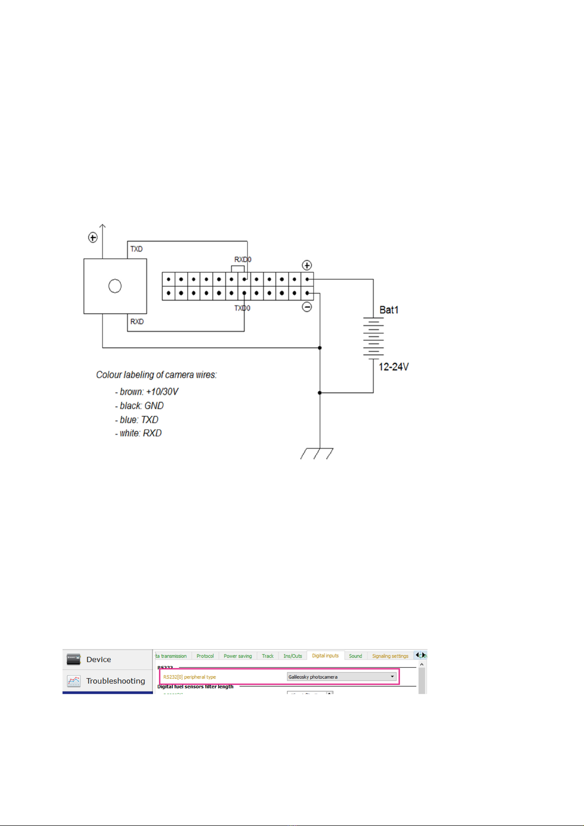
The camera is connected to the Galileosky v. 5.0 tracking unit via RS232 according to the
scheme resented in Picture 2.
The algorithm of connection and setting is the following:
1. Connect the contacts RXD, TXD, GND of the camera and TXD0, RXD0, GND of the
tracking unit corres ondingly.
ATTENTION! Grounds (GND) of the tracking unit and the camera must be connected,
RS232 contacts should be connected strictly according to the scheme: RXD of the camera
to TXD0 of the tracking unit and TXD of the camera to RXD0 of the tracking unit. Power
su ly is rovided se arately.
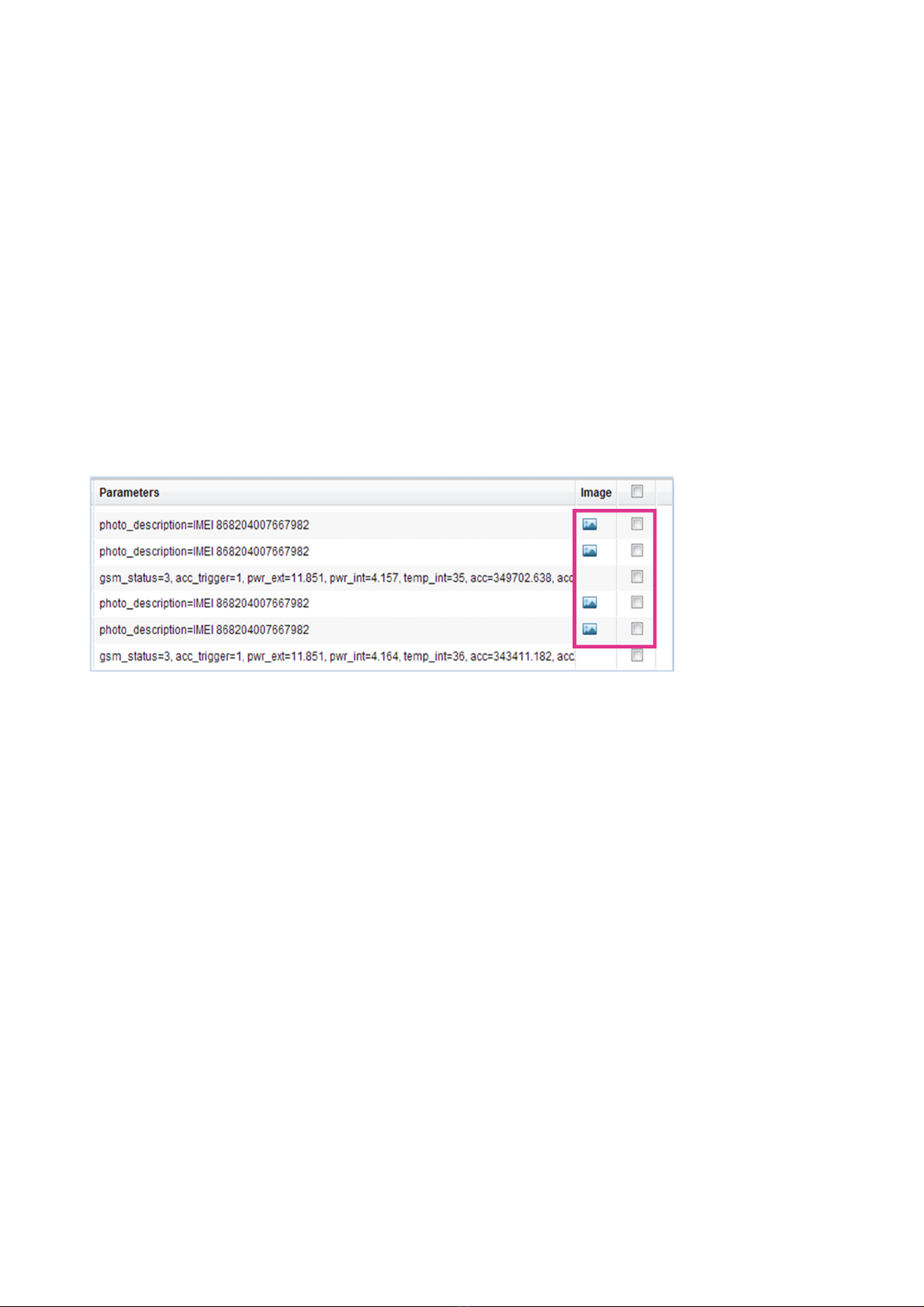
2. Insert a microSD card into the tracking unit in order to save the ictures.
3. Set RS232[0] in ut of the tracking device to o erate with the camera (Pic. 3):
- go to tab Settings -> Digital In uts and select “Galileosky hotocamera” or send
command RS2320 4 in the Commands tab;
- click A ly button;
Pic. 2
Connection scheme of the
camera to Galileosky v. 5.0
via RS232
Pic. 3
Settin s of RS232 input in the
Confi urator

RS232, RS485. Connection and O eration of Galileosky Photo Camera
(version 3 dated from August 8, 2018)
6
- go to tab Device in the Configurator and reset the tracking unit by clicking button
“Reset device” or in the Command tab send command “reset”.
4. Check if the tracking unit works with the camera correctly:
- go to tab Commands of Configurator service rogram and send command
“make hoto”;
- go to tab “Troubleshooting” and tick the o tion “RS232[0]”.
The exam le of troubleshooting message for firmware u to 229 is resented below:
RS232[0].cam. Sna shot start.
RS232[0].cam. ImageSize = 28160.
RS232[0].cam. Pic/RS0/20131025/043925.j g created successfully.
RS232[0].cam. rx ic.
- check LED of the camera – green LED on the camera blinks rarely (1 time er second)
when in standby mode and quickly (u to 10 times er second) during icture
recording.
5. Visually estimate the quality of the icture in the Device tab of Configuratoe
software (Pic. 4)
Pic. 4
Picture checkin in the
Confi urator

RS232, RS485. Connection and O eration of Galileosky Photo Camera
(version 3 dated from August 8, 2018)
7
Connecting Galileosky Photo
Camera via RS485 Interface
The camera is connected to the Galileosky v. 5.0 tracking unit via RS485 according to the
scheme resented in Picture 5.
The algorithm of connection and setting is the following:
1. Connect contacts RS485_A, RS485_B, GND of the camera and RS485_A,
RS485_B, GND of the tracking unit corres ondingly.
ATTENTION! Grounds (GND) of the tracking unit and the camera must be connected!
Power su ly is rovided se arately.
2. Insert a microSD card into the tracking unit to save ictures.
- set RS485 in ut of the tracking unit to work with the camera (Pic. 6):
- Go to the tab Settings -> Digital in uts and select “Photocamera and FLS”;
- click A ly button;
3. Make sure the tracking unit and the camera coo erate correctly:
Pic. 5
Connection scheme of the
camera to Galileosky v. 5.0
via RS485
Pic. 6
Settin RS485 input in
Confi urator

RS232, RS485. Connection and O eration of Galileosky Photo Camera
(version 3 dated from August 8, 2018)
8
- go to tab Commands of Configurator and send command “make hoto”;
- go to tab Troubleshooting and tick the o tion “RS485”.
The exam le of troubleshooting message for firmware u to 229 is resented below:
RS485.cam. Retrans ok.
RS485.cam. Sna shot start.
RS485.cam. ImageSize = 22176.
RS485.cam. Pic/RS4850/20131025/050953.j g created successfully.
RS485.cam. rx ic.
- check LED of the camera – green LED on the camera blinks rarely (1 time er second)
when in standby mode and quickly (u to 10 times er second) during icture
recording.

RS232, RS485. Connection and O eration of Galileosky Photo Camera
(version 3 dated from August 8, 2018)
9
Setting the Parameters of
Photo Camera Operating
You can set additional arameters of o eration with the camera in the tab settings -> Digital
in uts (Pic. 7), or by the command PhotoCfg (see the descri tion in the A endix 1).
1. First of all set the Recording eriod which is an interval of frequency with which ictures
are taken aand saved to the microSD card. When the value “0” is set, recording by
event is carried out, in other words when the
make hoto
command is given or when
signaling conditions are triggered.
2. Parameter “Recording and send eriod” defines an interval of frequency in which
ictures are taken, saved to the microSD card and sent to the server. When the value
is 120 or lower, recording is carried out by event. In order the ictures were
transmitted to the server correctly, make sure the server arameters are set correctly.
(Pic. 8).
Pic. 7
Settin the parameters of
photo makin in Confi urator
Pic. 8
Settin the operation
parameters of the camera in
Confi urator software

RS232, RS485. Connection and O eration of Galileosky Photo Camera
(version 3 dated from August 8, 2018)
10
3. Parameter “Recording in geofence” defines the behavior of the tracking unit on taking
ictures by the camera de ending on the use of Geofences.
4. Parameter “Size” allows you to set the icture resolution: 640х480 or 320х240
oints. If GPRS-connection is not very good, it is recommended to set a lower
resolution which would allow increase the s eed of ictures transmission to the
monitoring server.
5. The last arameter “Require an acknowledgment from server” defines the server
behavior when receiving a icture. As the ictures are divided into arts and
transmitted to the server in this way because of the big size, in case of lack of
confirmation by the server and loss of one of the ackets the whole icture is lost.
Therefore, it is necessary to set this arameter for guaranteed transmission of the
icture.
Camera ca tures received by the monitoring software are dis layed in the column
“Image” in the monitoring software (Pic. 9).
Pic. 9
Example of pictures display in
the monitorin server

RS232, RS485. Connection and O eration of Galileosky Photo Camera
(version 3 dated from August 8, 2018)
11
Uploading Photos from
MicroSD Card
Pictures from the camera, which is connected to zero in ut RS232[0], are saved to the micro
SD card to the catalog Pic\RS0, to the in ut RS232[1] – to the catalog Pic\RS1. Pictures
from the camera, which is connected to in ut RS485, are saved to the micro SD card to the
catalog Pic\RS4850. For each date there is a se arate catalog created. Files names are
formed by the time of shooting.
All the ictures taken by the camera and saved in microSD card can be dis layed and (or)
u loaded to the com uter in two ways:
1. Remove the microSD card from the tracking unit, connect it to the com uter and save
the ictures focusing on the file catalog structure listed above;
2. Some of the images can be requested remotely through monitoring software or SMS-
command. For that send command
Get hoto
with necessary arameters (see the
descri tion in A endix 1).
Connection of Galileosky hoto camera and Galileosky tracking unit is com leted,
the tracking device is ready for use.
RSA “Galileosky”, LLC roduces satellite monitoring equi ment for GPS and GLONASS
real time vehicles monitoring. The tracking devices determine the mobile object location
recording the time and route as oints with geogra hical coordinates and send the data to
the server to be further rocessed and sent to the traffic controller anel.
In addition, a number of other vehicle arameters are recorded: the state of analog and
discrete in uts of the tracking device and the state of digital interfaces.
The tracking devices can be used in any vehicle.

RS232, RS485. Connection and O eration of Galileosky Photo Camera
(version 3 dated from August 8, 2018)
12
APPENDIX 1
Photo camera o eration settings
Command format
GetPhoto d,t,n
Parameters
d – hoto date, format DDMMYY, where DD – day, MM – month, YY – year;
t – hoto time, format HHMMSS, where HH – hours, MM – minutes, SS – seconds;
n – ort number to which the camera taking hotos is connected:
Explanation
Request to transmit the nearest to the given time and data hoto to the server.
Example
Request: GetPhoto 050511,052030,0
Re ly: Send of hoto is scheduled
Command format
PhotoCfg t1,t2,mode,res,confirm
Parameters
t1 – eriodical shooting interval, [sec]. Photos are saved only to the SD-card, 0 – shooting
only by event;
t2 – shooting interval [sec]. Photos are saved to the SD-card and sent to the server, 0 –
shooting only by event;
mode – eriodical shooting in geofences:
0 – hotos are taken regardless of geofences;
1 – hotos are taken only inside geofences;
2 – hotos are taken only outside geofences.
res – icture resolution:
0 – 640х480 oints;
1 – 320х240 oints.
confirm – waiting for a confirmation of a icture rece tion from the server:
0 – do not wait;
1 – wait.
Explanation
Settings of a eriodical camera shooting, icture format and image transfer rotocol..
Example
Request: PhotoCfg 5,150,0,0,0
Re ly: PHOTOCFG:WrPeriod=5,SendPeriod=150,Ty e=0,Size=0,Confirm=0;

RS232, RS485. Connection and O eration of Galileosky Photo Camera
(version 3 dated from August 8, 2018)
13
Command format
MakePhoto
Explanation
Take a hoto and send it to the server
Example
Request: MakePhoto
Re ly: Photo ok
Table of contents