Gallien-Krueger 1000RB User manual

Operating
Instructions
1000RB

Table of Contents
INTRODUCTION ………………………………………………………. 3
1000RB FEATURES ……………………………………………………. 3
FRONT PANEL FEATURES …………………………………………… 4
REAR PANEL FEATURES …………………………………………… 5
HOOKING UP YOUR SPEAKERS …………………………………… 6
GETTING YOUR SOUND ……………………………………………. 6
TROUBLESHOOTING ……………………………………………….. 7
USING EFFECTS ……………………………………………………… 8
2

We are very proud of the 1000RB, G-K's most pow-
erful bass amplifier to date, and in many ways, the
culmination of 27 years in the amplification busi-
ness. The 1000RB was designed with you in mind -
to be your personal creative tool, to give you the ulti-
mate bass response and tone. We've learned many
things by talking to bass players like you for almost
three decades. We know you want lots of headroom
and raw power, yet you want your amp to be dead
quiet and free of noise. Your need fast response and
clarity. And perhaps most of all, you want all that
great performance night after night, year after year,
from an amp that will never let you down.
The 1000RB is definitely not just another high power
bass amp. Its High Current Capacity output stages-
capable of delivering instantaneous power of 5,000
watts - are revolutionary. Its relay-activated Fault
Detection Circuitry is state - of - the art. All the
design parameters for the 1000RB are optimized for
response, headroom, and reliability.
Like all G-K bass amps, the 1000RB is user friendly.
It's easy to get the sound you're looking for - in fact,
it is hard to get a bad sound. We took all the same
responsive bass tone G-K amps are known for, and
made it even better. We think you will be very
pleased with your new 1000RB. We are.
Bob Gallien & Rich Krueger
Introduction
Power : 500 watts RMS into 4 ohms
High Current Capacity : 60 amps peak current
(5,000 watts of instantaneous power) gives the
1000RB unparalleled transient response with
complete control over the movement of your
speakers.
Low Noise Operation : Both preamp and power
amp stages have increased headroom so that
noise ( hiss ) is barely perceptible.
Fault Detection Circuitry : Relays automatically
disconnect the amplifier from your speakers
during power up/down, or if any unsafe
operating conditions occur.
Fan Cooling : Temperature controlled, continuously
variable fan speed.
Tuner output with footswitchable mute.
Tunable Voicing Filters
Four Band Active Equalization
Boost 1 (Normal) & Boost 2 (High Gain) :
Footswitching between these two sections.
GIVE Technology : Gate Induced Valve Effect,
used throughout for warm, "punchy" response.
Parallel effects loop with Stereo Aux In and Aux
Return Level
Direct/balanced output : Electronically balanced,
low impedance output with variable level,
pre/post & ground lift switches.
Speakonconnectors : For reliable connection of
high power / high current outputs to speaker
cabinets.
1000RB Features
3

(1) INPUT JACK
1/4'' phone jack to plug in active or passive basses with a
shielded cord
(2) -10 dB PAD
This switch should be pressed if the CLIP(3) light stays on
continuously. It may be necessary to "pad" the input if you are
using a bass with active electronics or very high output.
(3) CLIP
LED indicator which lights when the input stage is being over-
driven. If -10dB PAD (2) is pressed and CLIP(3) still stays lit,
turn down the volume on your bass.
(4) TUNING MUTE
Switch that mutes all outputs from the amplifier (speakers, direct
and balanced outs) so you can tune up without sending signal to
the audience or the P.A.. Tuning mute can be footswitch con-
trolled by using a G-K RF2 footswitch, which will leave both
hands free to tune your instrument. To control TUNING MUTE
by footswitch, TUNING MUTE (4) switch must be "in"
(5) LED INDICATOR
Lights when TUNING MUTE is activated.
(6) VOLUME
Controls signal level at the beginning of preamp stages.
Volume should be turned up until the CLIP(7) light comes on
when you're hitting your loudest notes. At this setting you will
have the optimum signal/noise ratio. Remember that your set-
tings in the VOICING FILTER and ACTIVE EQUALIZATION
sections can also cause clipping. IF this occurs, re-adjust
VOLUME as explained above.
(7) CLIP
LED indicator that lights when either VOLUME, VOICING
FILTER, OR ACTIVE EQUALIZATION stages are being over-
driven.
(8) BOTTOM
Voicing filter which boosts or cuts +/-12dB at very low frequencies
(20Hz center freq.). Boost this control if you want to add more
low-bass response. Or, keep it turned down if you want a tighter,
less "boomy" bottom end.
(9) CONTOUR
Voicing filter that boosts highs (4kHz) and lows (80Hz), while
dropping out mids (600Hz). Most players use this control
between half and maximum to create a "round" or "hi-fi" sound.
Use lower settings for a "flatter" response.
(10) PRESENCE
Voicing filter that boosts high frequencies (6.5kHz center freq.)
by as much as 12dB. This control adds "edge" to help you cut
through the mix.
(11) - (14) ACTIVE EQUALIZATION
Four highly active tone controls, TREBLE, HI MID, LO MID,
AND BASS. Each band of EQ creates wide tonal variations
without affecting the other bands.
(15) BOOST 1
A post EQ gain stage using GIVE Technology which adds
"growl" as you turn it up. The RF2 footswitch allows you to
switch between BOOST1 and BOOST 2.
(16) LED INDICATOR
Lights when you have footswitched into the BOOST 2 mode.
(17) BOOST 2
A post EQ gain stage like BOOST 1, except this stage has higher
gain for "lead-bass" or solos. Use BOOST 2 with LEVEL (18)
to create the desired amount of overdrive. Note: You can only
access the BOOST 2 section via the RF2 footswitch.
(18) LEVEL
Determines the level coming out of BOOST 2 section. Used to
set a different volume level for solos.
(19) AUX LEVEL
Controls signal level coming from AUX IN(26). Creates effects
blend (dry vs. wet) when used in a "parallel" effects loop.
(20) MASTER
Master volume that controls output level to speakers.
(21) POWER SWITCH
(22) PROTECT
LED indicator that lights on power up, power down, or when-
ever the FAULT DETECTION CIRCUITRY relays have discon-
nected the 1000RB from your speakers.
(23) CLIP
LED indicator that lights when the output is clipping.
(24) POWER
LED indicator that lights during normal operation.
Front Panel Features
4

Note : The block diagram of the 1000RB is printed on the rear
panel and describes the signal flow from input to output. Many
of your questions about the use and functions of the 1000RB are
explained in this diagram.
(25) FOOTSWITCH RF2
1/4'' stereo phone jack that connects to RF2, two button
footswitch, via stereo cable. This jack is wired so that TUNING
MUTE is controlled by the "tip", BOOST 2 is controlled by the
"ring", and the "sleeve" is ground.
(26) AUX IN
1/4'' phone jack that accepts a line level input. Can be used as an
effects return in a "parallel" effects loop.
(27) RETURN
Accepts line level return from external effects that are connected
in a "series loop" (such as limiters, enhancers, etc.). Plugging
into RETURN opens the connection between the 1000RB pre-
amp and power amp stages.
(28) SEND
Line level output that is post EQ and pre BOOST. Used when
sending a full range mono signal to an external device (effects or
slave amp).
(29) PRE/POST
Select the source for the XLR balanced output(32). In the "out"
position, the direct output is PRE meaning that it comes right off
the input stage, (after TUNING MUTE, before VOLUME), and
is unaffected by any front panel controls except the -10dB PAD
switch. The PRE position is used to take a balanced direct out-
put to the house PA in a live situation where the soundman wants
a signal unaffected by your VOLUME and EQ controls. In the
"in" position the balanced output is POST (comes from the last
point in the preamp, just before the master volumes) and is
affected by all the front panel controls. A POST balanced out-
put can be used for recording.
(30) BAL. LEVEL
Adjusts signal level of balanced output (32).
(31) GND LIFT
Ground lift switch that disconnects ground on balanced output
(32) to eliminate hum.
(32) Bal. Out
XLR connector with electronically balanced, low impedance
output, used to send signal to P.A. or recording consoles. Wiring
for the XLR is "American Standard" : Pin 1 is ground, pin 2 is +,
and pin 3 is-.
(33) TUNER OUT
Output that comes directly off the input stage, and can be
patched to a tuner with a shielded patch cord.
(34)&(35) SPEAKONCONNECTORS
Deliver power to your speaker(s). Cables with Speakoncon-
nectors are recommended because of the high power/current out-
put of the 1000RB. Refer to the section titled "HOOKING UP
YOUR SPEAKERS" for recommended Speakoncables.
(36) & (37) 1/4'' CONNECTORS
Provided as back-up outputs. 1/4'' connectors do not have the
same power handling as Speakonconnectors, and should only
be used if Speakoncable are unavailable.
(38) AC RECEPTACLE
Plug the power cord that is included with the 1000RB into this
receptacle.
Rear Panel Features
5

Hooking Up
Your Speakers
Before you power up your 1000RB, make sure your speaker cab-
inets are compatible with your amp. Remember, you can not
hook up a combined speaker impedance which is less than
4ohms to your 1000RB. Anything over 4 ohms is OK. Using
more speaker cabinets than recommended will drop your com-
bined speaker impedance below 4 ohms, which could result in
the Fault Detection System disconnecting your 1000RB from
your speakers. Refer to the chart below:
A note regarding speaker cable: The 1000RB is capable of deliv-
ering more power than typical speaker cables can handle. We
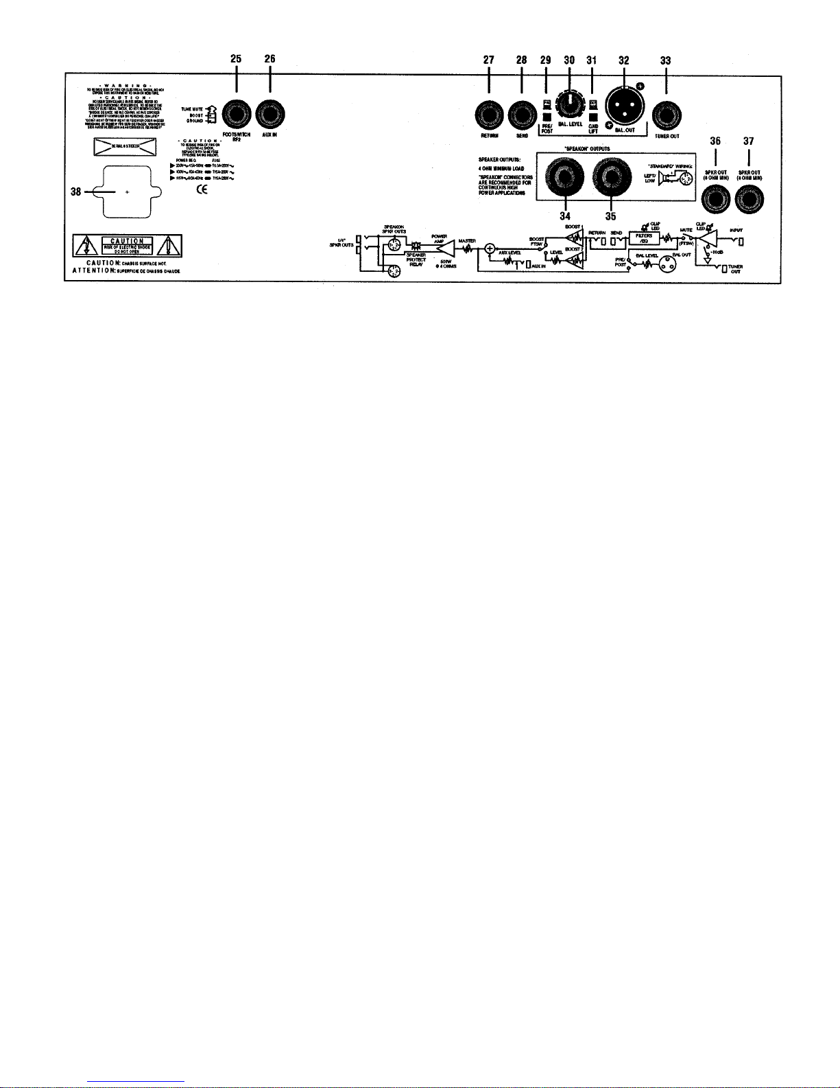
therefore recommend Speakonspeaker cables. Choose cables
that are compatible with the connectors on your speaker cabinets.
These can be purchased through your G-K dealer.
G-K part no.: 304-0007-0 (Speakon-1/4" , "Normal" cable)
G-K part no.: 304-0009-0 (Speakon-"banana", "Normal" cable)
G-K part no.: 304-0011-0 (Speakon- Speakon, "Normal" cable)
Getting Your Sound
Your should have your speakers hooked up with the recom-
mended cables. Now, connect the power cord to your amp and
to a rounded (3prong) AC outlet that has at least 20 amps of
capacity. Use a power cord which is 16 gauge or heavier.
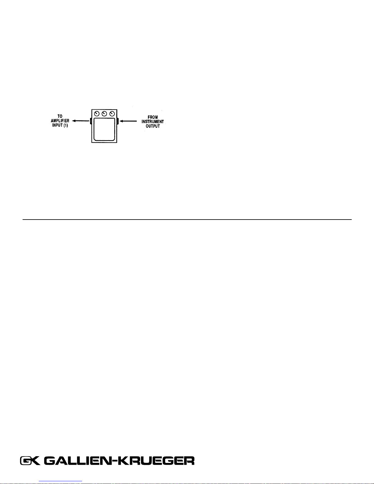
1. PLUG IN YOUR BASS
For starters, turn the volume on your bass all the way up. You
may need to adjust this later. If you have conventional tone con-
trols on your bass, turn them all the way up. If your bass has
active tone controls that boost and cut, set them in the flat posi-
tion. You can fine tune these tone controls after you finish the
following instructions.
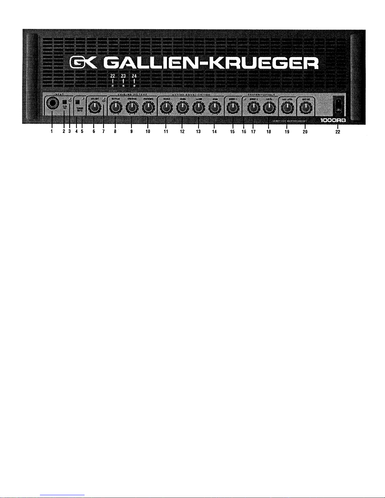
2. INITIAL FRONT PANEL SETTINGS
Start by setting these front panel controls at 12 O’clock:
VOICING FILTERS (BOTTOM, CONTOUR, PRESENCE),
ACTIVE EQUALIZATION (TREBLE, HI MID, LO MID,
BASS), BOOST1 and BOOST2. Turn down VOLUME and
MASTER control.
3. POWER UP
Turn on the power switch and wait about 5 seconds for the PRO-
TECT lights to go off and the POWER lights to come on. This
indicates that the system checks OK and protection relays have
connected the 1000RB to your speakers.
4. CHECK TO SEE IF -10dB PAD IS REQUIRED
Play a few notes and notice if the CLIP (3) LED stays on con-
tinuously. If so, press the -10dB PAD(2) to prevent clipping in
the input stage. The CLIP indicator should only light when you
hit your loudest notes. If it stays lit after you have pressed the -
10dB PAD, turn down the volume on your bass.
5. ADJUST VOLUME FOR LOW NOISE OPERATION
Turn up VOLUME(6) as you play, and set it so the CLIP (7)
LED comes on with your loudest notes. Save this setting-it will
give you the best signal to noise ratio. You may have to come
back and re-adjust VOLUME once you have found VOICING
FILTER and ACTIVE EQ settings you like. You may have to
reduce VOLUME (which also determines the SEND level) to
prevent your external effects from being overdriven. You can
now set the MASTER control for comfortable listening.
6. VOICING FILTERS
CONTOUR:
Many players like CONTOUR, so start by setting this control
between 12 and 3 O’clock. CONTOUR drops mids while boost-
ing highs and lows, which creates a "round" sound. If you like a
flatter response ("funk" e.g.)try experimenting with CONTOUR
settings between 9 and 12 O’clock.
BOTTOM:
If you want lots of low end response, try boosting BOTTOM
above 12 O’clock. If you want the tone of older G-K amps, try
setting Bottom between 10 and 12 O’clock.
PRESENCE:
Presence will add "edge" so you can cut through the mix. Try
settings below and above 12 O’clock until you find one you like.
Note: PRESENCE adds high end-too much can also create
unwanted "hiss".
7. ACTIVE EQUALIZATION
Once you have your VOICING FILTER settings, use the
ACTIVE EQ to "tailor" your tone. While you play, adjust each
EQ control all the way up and all the way down from the center
position, until you find settings you like. Let your ears be the
judge. There are no EQ settings that can harm your amp.
8. BOOST 1
Most players use BOOST because it adds "growl" (an effect that
is very noticeable but hard to describe). Start with BOOST 1 set
between 10 and 1 O’clock, and experiment with settings above
and below.
9. BOOST 2 & LEVEL
BOOST 2 (which is only activated by footswitch) gives you a
more pronounced BOOST effect for solos. In the higher set-
tings, BOOST 2 is slightly overdriven. Use LEVEL to set your
volume for solos.
10. MASTER
Now that you have your basic tone, use the MASTER control to
set your loudness(stage volume).
6

SYMPTOM POSSIBLE CAUSE POSSIBLE SOLUTION
NO LIGHTS UNIT NOT PLUGGED IN CONNECT POWER CORD TO AC OUTLET,
CHECK AC OUTLET
UNIT HAS FAILED REFER TO SERVICE TECHNICIAN
POWER LED ON BUT SHORTED SPEAKER CORD REPLACE W/DIFFERENT CABLE
FAULT LED ALSO ON SPEAKER IMPEDANCE TOO LOW CHECK MANUAL FOR RECOMMENDED
SPEAKER LOADS
AMP HAS OVERHEATED TURN AMP OFF, WAIT&TURN ON
CHECK SPEAKER IMPEDANCES
AMP HAS FAILED REFER TO SERVICE TECHNICIAN
POWER LED ON BUT TUNING MUTE ON TURN TUNING MUTE OFF
NO SOUND EFFECT IN LOOP TURNED OFF TURN EFFECT ON
VOLUME, BOOST,MASTERS OFF TURN CONTROLS UP
INSTRUMENT TURNED OFF TURN INSTRUMENT VOLUME UP
BAD GUITAR CABLE REPLACE CABLE
BAD BATTERY IN ACTIVE BASS CHECK BATTERY
COMPONENT FAILURE REFER TO SERVICE TECHNICIAN
HUM AND/OR NOISE PICKUPS TOO CLOSE TO AMP OR TRY MOVING,TURN OFF LIGHTS,
OR OTHER ELECTRICAL DEVICE OR OTHER ELECTRONIC DEVICES
BAD GUITAR CABLE REPLACE CABLE
COMPONENT FAILURE REFER TO SERVICE TECHNICIAN
DISTORTION INPUT STAGE CLIPPING PRESS-10Db SWITCH, TURN
DOWN BASS
PREAMP CLIPPING TURN DOWN VOLUME, ADJUST EQ
EFFECTS CLIPPING TURN DOWN VOLUME, BOOST OR
LEVELS ON EFFECTS
POWER AMP CLIPPING TURN DOWN VOLUME, BOOST OR MASTER VOLUME
BAD BATTER IN ACTIVE BASS CHECK BATTERY
COMPONENT FAILURE REFER TO SERVICE TECHNICIAN
LOUDNESS IS EFFECTS NOT HOOKED UP CHECK MANUAL FOR USING
BELOW NORMAL CORRECTLY EFFECTS
WRONG SPEAKON CABLE USE NORMAL SPEAKON CABLE,
NOT BRIDGE MODE CABLE
HUM IN DIRECT OUT GROUND LOOP PRESS GROUND LIFT SWITCH
DISTORTION IN DIRECT SIGNAL TOO "HOT" TURN DOWN BAL.LEVEL CONTROL
TUNING MUTE BAD CORD FOR RF2 FOOTSWITCH REPLACE CORD
AND/OR BOOST2 RF2 DEFECTIVE REFER TO SERVICE TECHNICIAN
NOT WORKING COMPONENT FAILURE REFER TO SERVICE TECHNICIAN
Troubleshooting
GALLIEN-KRUEGER • 2240 PARAGON DR. • SAN JOSE, CA 95131
US: (408) 441-7970 • FAX (408) 441-8085
EUROPE: 41.42.234520 • FAX: 41.42.239525
7

Using Effects
1. In line with the input
Effects like compression work best when connected in line with
the input of the 1000RB. Many players also connect other
"stomp box" type effects in line with the input because it is so
easy. Except for compression, however, this is not the best con-
figuration for low noise, since it amplifies any noise created in
your effects by the gain of the whole amplifier.
Come out of your instrument with a shielded patch cord, into the
effects unit, and from there into the INPUT of the 200RB.
2. "Series" effects loop
A "Series" effects loop is a simple and effective way to use
effects like chorus, delay, or reverb with the 1000RB. It is also
the best configuration for a limiter. Putting effects in a "loop"
results in much lower noise than "in line with the input". In a
"series" effects loop, effects are connected in "series" between
the 1000RB's preamp and power amp stages. Connect SEND(28)
to the "mono" input of an external (effects) device. Come out of
the "mono" output of your effects unit into RETURN(27).
SEND(28) is post VOLUME, and post EQ. If the SEND signal
is too "hot", it can overdrive your effects unit, and it may be nec-
essary to reduce VOLUME (6) until the unwanted distortion in
your effects goes away.
3. 'Parallel" effects loop
Also known as a "side chain", this configuration works like the
"effects buss" on a professional mixing console.
A line level signal is taken from either SEND(28), routed to an
external effects unit, and finally brought back to the 1000RB via
the AUX IN(26). Then AUX LEVEL(19) is used to mix the
effects signal with the main signal, which creates an effects
blend(''wet" vs. "dry").
GALLIEN-KRUEGER • 2240 PARAGON DR. • SAN JOSE, CA 95131
US: (408) 441-7970 • FAX (408) 441-8085
EUROPE: 41.42.234520 • FAX: 41.42.239525
Table of contents
Other Gallien-Krueger Musical Instrument Amplifier manuals

Gallien-Krueger
Gallien-Krueger 800RB User manual

Gallien-Krueger
Gallien-Krueger Backline 100 User manual

Gallien-Krueger
Gallien-Krueger 250ML User manual

Gallien-Krueger
Gallien-Krueger 400RB-III User manual

Gallien-Krueger
Gallien-Krueger 200MB User manual

Gallien-Krueger
Gallien-Krueger Backline 100 User manual

Gallien-Krueger
Gallien-Krueger 250ML User manual