Gardenline GL-BC 25S User manual

AFTER SALES SUPPORT
1
After Sales Support
Now you have purchased a
Gardenline®product you can rest
assured in the knowledge that as
well as your 1 year parts and labour
guarantee you have the added
peace of mind of dedicated helplines
and web support.
25cc Petrol Brush Cutter
User Guide

AFTER SALES SUPPORT
2
Warranty Details
The product is guaranteed to be free from defects in workmanship and parts for a
period of 12 months from the date of purchase. Defects that occur within this
warranty period, under normal use and care, will be repaired, replaced or refunded
at our discretion. There will be no returns accepted with products containing fuel.
The benefits conferred by this warranty are in addition to all rights and remedies in
respect of the product that the consumer has under the Competition and Consumer
Act and similar state and territory laws.
Our goods come with guarantees that cannot be excluded under the Australian
Consumer Law. You are entitled to a replacement or refund for a major failure and
for compensation for any other reasonably foreseeable loss or damage. You are also
entitled to have the goods repaired or replaced if the goods fail to be acceptable
quality and the failure does not amount to a major failure.
Please note: No returns to stores will be accepted with products containing fuel.
25cc Petrol Brush Cutter
After Sales Support
Telephone: 1300 922 271
Email: [email protected]
1

AFTER SALES SUPPORT
3
Contents
10 Safety Information
10 Layout
10 Items Supplied
13 Intended Use
13 Technical Data
13 Before Starting The Equipment
15 Operations
16 Cleaning, Maintenance and Ordering Spare Parts
17 Storage and Transport
18 Disposal and Recycling
19 Troubleshooting
What your 1 year warranty means
Congratulations on choosing to buy a Gardenline®product. By doing so you now have the
assurance and peace of mind that comes with purchasing a product made by one of Australia’s
leading suppliers.
All products brought to you by Gardenline®are manufactured to the highest standards of
performance and safety, and, as part of our philosophy of customer service and satisfaction, are
backed by our comprehensive 1 Year Guarantee.
Please fill in and return the Guarantee Card to the address provided.
We hope you will enjoy using your purchase for many years to come.

AFTER SALES SUPPORT
4
3
1
3
1
2
2
32
222325
26
24
27
28
29
30
10
13 14b
14a 15 16 17 18 19 20 21
15
5
912
11
6
7
8
4

AFTER SALES SUPPORT
5
5a 6a5b
24
27 26 25 16
4a 4c4b
21
2
22
AC
B
6c6b
26
16
23
3a 3c3b
6d 25

AFTER SALES SUPPORT
6
5
6f6e
27
31
20
7b
7a
7c
8b
8a
8c 8d
31
8f8e 9a

AFTER SALES SUPPORT
7
6
11a
12a
11b
9c 9d
9e 9f
12b
10b
10a
9b
12c

AFTER SALES SUPPORT
8
7
12d 12e 12f
13a 13b
D
B
A
C
E

AFTER SALES SUPPORT
10
Important!
When using equipment, a few safety precautions
must be observed to avoid injuries and damage.
Please read the complete operating manual with due
care. Keep this manual in a safe place, so that the
information is available at all times. If you give the
equipment to any other person, give them these
operating instructions as well.
We accept no liability for damage or accidents which
arise due to non-observance of these instructions
and the safety information.
Safety Information 1
CAUTION!
Read all safety regulations and instructions.
Any errors made in following the safety regulations
and instructions may result in an electric shock, fire
and/or serious injury.
Keep all safety regulations and instructions
in a safe place for future use.
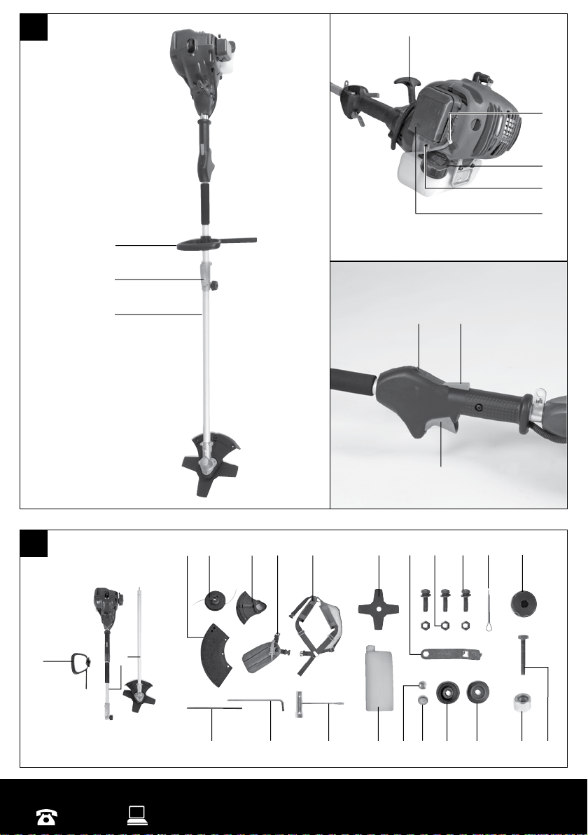
Safety Devices
When working with the equipment, the appropriate
plastic guard hood for cutting blade mode or cutting
line mode must be fitted to prevent objects being
thrown out by the equipment. The integrated blade
in the cutting line guard hood automatically cuts the
line to the optimum length.
Explanation of the information signs on the
equipment:
1. Warning:
2. Read the directions for use before operating the
equipment.
3. Wear safety goggles, a face guard and ear
protection.
4. Wear sturdy, non-slip footwear.
5. Wear safety gloves.
6. Protect the equipment from rain and damp.
7. Be careful of objects being thrown out!
8. Always switch off the equipment and pull out
the spark boot plug before carrying out any
maintenance work.
9. All bystanders must be kept at least 15m from
the equipment.
10. The tool continues to rotate!
11. Caution: Hot equipment parts. Keep your
distance.
Safety Information
1. Read the directions with due care. Familiarise
yourself with the settings and proper operation
of the machine.
2. Never allow children or other persons who are
not familiar with the operating instructions to
use the petrol power scythe. Contact your local
governmental agency for information regarding
minimum age requirements for operating the
petrol power scythe.
3. Never mow in the direct vicinity of persons -
especially children - or animals.
Warning:
Maintain a safety distance of 15m. If
approached, switch off the appliance
immediately.
Always keep in mind that the machine operator
or user is responsible for accidents involving
other persons and/or their property.
Preliminary measures
1. Always wear sturdy, non-slip footwear and long
trousers when mowing.
2. Check the grounds on which the machine will
be used and remove all objects that could be
caught up and violently flung out.
3. Warning:Petrol is highly flammable! Therefore:
- Only store petrol in containers designed to
hold petroleum-based liquids.
- Only refuel out in the open and do not smoke
during the refueling process.
- Always refuel before starting the engine. Do
not open fuel tank cap and do not refuel when
the engine is running or when the scythe is hot.
- If petrol has overflowed, do not under any
circumstances attempt to start the engine.
Instead, remove the machine from the affected
area. Avoid starting the engine until the petrol
fumes have completely evaporated.
For safety reasons, the petrol tank and other
tank closures must be replaced if they are
damaged.
4. Replace defective mufflers.
5. Before using the scythe, visually inspect it to
ensure that the blade, mounting bolts and the
entire cutting apparatus are in good working
order (i.e. not worn out or damaged). To prevent
any imbalance, replace worn out or damaged
blades and mounting bolts as a set only (if
applicable).
6. The powered equipment will create toxic
exhaust fumes as soon as the engine is started.
Never work in enclosed rooms or in rooms with
poor ventilation.
Handling
1. Wear close fitting, tough work clothing
that will provide protection, such as long slacks
or trousers, safety work shoes, heavy duty work
gloves, hard hat, a safety face shield, or safety
glasses for eye protection and a good grade of
ear plugs or other sound barriers for hearing
protection.

AFTER SALES SUPPORT
11
2. Store in a safe place. Open fuel cap slowly
to release any pressure which may have formed
in the fuel tank. To prevent a fire hazard, move
at least 10 feet (3 meters) from fueling area
before starting.
3. Turn unit off before setting it down.
4. Always hold unit firmly with both hands,
the thumb and fingers encircling the handles.
5. Keep all screws and fasteners tight.
Never operate your equipment when it is
improperly adjusted or not completely and
securely assembled.
6. Keep handles dry, clean and free of fuel
mixture.
7. Keep stringhead as close to ground as
practical. Avoid hitting small objects with
stringhead. When cutting on a slope, stand
below ringhead. NEVER cut or trim on a hill
or slope, etc. if there is the slightest chance of
slipping, sliding or losing firm footing.
8. Check area you will be trimming for
debris that may be struck or thrown during
operation.
9. Keep all parts of your body and clothing
away from stringhead when starting or
running engine. Before starting engine, make
sure stringhead will not come in contact with
any obstacle.
10. Stop engine before examining cutting line.
11. Store equipment away from possible
flammable materials, such as gas-powered
water heaters, clothes dryers, or oil-fired
furnaces, portable heaters, etc.
12. Always keep the debris shield, stringhead,
and engine free of debris build-up.
13. Operation of equipment should always be
restricted to mature and properly instructed
individuals.
14. If unfamiliar with trimming techniques,
practice the procedures with engine in “OFF”
position.
15. Always clear work area of debris such as
cans, bottles, rocks, etc. Striking objects can
cause serious injury to operator or bystanders
and also damage equipment. If an object is
accidentally hit, immediately turn engine off
and examine equipment. Never operate unit
with damaged or defective equipment.
16. Always trim or cut at high engine
speeds. Do not run engine slowly at start or
during trimming operations.
17. Do not use equipment for purposes other than
trimming or mowing weeds.
18. Never raise stringhead above knee height
during operation.
19. Do not operate unit with other people or
animals in the immediate vicinity. Allow a
minimum of 50 feet (15 meters) between
operator and other people and animals when
trimming or mowing. Allow a distance of
100 feet (30 meters) between operator and
other people and animals when scalping with
stringhead cutter.
20. If operating unit on a slope, stand below
the cutting attachment. Do not operate on a
slope or hilly incline if there is the slightest
chance of slipping or losing your footing.
21. In case of equipment with a coupling,
make sure tha the cutting tool does not turn in
idling mode.
Additional instructions
1. DO NOT USE ANY OTHER FUEL than that
recommended in your user guide. Always follow
instructions in the Fuel and Lubrication section
of this manual. Never use petrol unless it is
properly mixed with 2-cycle engine lubricant.
Permanent damage to engine will result,
voiding manufacturer’s warranty.
2. DO NOT SMOKE while refueling or operating
equipment.
3. DO NOT OPERATE UNIT WITHOUT A
MUFFLER and properly installed muffler
shield.
4. DO NOT TOUCH or let your hands or body
come in contact with the muffler. Hold unit with
thumbs and fingers encircling the handles.
5. DO NOT OPERATE UNIT IN AWKWARD
POSITIONS, off balance, outstretched arms,
or one-handed. Always use two hands when
operating unit with thumbs and fingers
encircling the handles.
6. DO NOT RAISE STRINGHEAD above ground
level while unit is operating. Injury to operator
could result.
7. DO NOT USE UNIT FOR ANY PURPOSES
OTHER than trimming lawn or garden areas.
8. DO NOT OPERATE UNIT FOR
PROLONGED PERIODS. Rest periodically.
9. DO NOT OPERATE UNIT WHILE UNDER
THE INFLUENCE OF ALCOHOL OR DRUGS.
10. DO NOT OPERATE UNIT UNLESS DEBRIS
SHIELD AND/OR GUARD IS INSTALLED
AND IN GOOD CONDITION.
11. DO NOT ADD, REMOVE OR ALTER ANY
COMPONENTS OF THIS PRODUCT.
Doing so could cause personal injury and/or
damage the unit voiding the manufacturer’s
warranty.
12. DO NOT operate your unit near or around
flammable liquids or gases whether in or out of
doors. An explosion and/or fire may result.
13. DO NOT USE ANY OTHER CUTTING
TOOLS. For your own safety only use the
accessories and additional equipment specified
in the operating manual or recommended or
specified by the manufacturer. The use of tools
or accessories other than those recommended in
the operating manual or catalogue may place
you in danger of personal injury.

AFTER SALES SUPPORT
12
Safety when handling the blade
1. FOLLOW ALL WARNINGS and instructions
for using the machine and for installing the
blade.
2. The blade may suddenly jump away
out of control if it comes up against
objects which cannot cut through. This
may result in the amputation of arms
or legs. Keep onlookers and animals at least
15m away from where you are working. If the
machine strikes a foreign body, stop the engine
immediately and bring the blade to a standstill.
Check the blade for signs of damage. Always
replace the blade if it is bent or torn.
3. THE BLADE WILL THROW UP OBJECTS
AT HIGH SPEED: This may cause blinding
injuries. Always wear eye, face and leg
protection. Remove all objects from the
working area before using the blade. Keep
other people and animals at least 15m away
from the machine in all directions.
4. Check your machine and other
equipment carefully for signs of
damage. Do not use the machine unless
all the blade mountings have been installed
correctly.
5. THE BLADE WILL SLOW DOWN AND
STOP IF YOU RELEASE THE THROTTLE
VALVE (petrol lever). While it is slowing down,
the blade can still cut you or onlookers. Before
you carry out any work on the blade, switch off
the engine and make sure that the blade has
stopped.
6. DANGER ZONE WITH A DIAMETER OF
15 METERS. Onlookers may suffer blindness
or injuries. Keep onlookers and animals at least
15m away from where you are working.
Layout (Fig. 1/2) 2
1. Connecting piece for long handle
2. Long handle
3. Steady grip
4. Starter cable
5. Choke lever
6. Tank
7. Fuel pump “primer”
8. Air filter housing cover
9. ON/OFF switch
10. Locking pin
11. Throttle lever
12. Throttle lever lock
13. Line spool with cutting line
14a. Cutting line guard hood
14b Cutting blade guard hood
15. Comfort carrying belt
16. Cutting blade
17. Key for changing the spool
18. Nut for guard hood (3x)
19. Screw for guard hood (3x)
20. Safety split pin
21. Handle screw
22. Connecting screw
23. Spacer sleeve
24. Spacer bush (already assembled)
25. Fastening ring
26. Carrier plate
27. Nut
28. Oil/petrol mixing bottle
29. Spark plug wrench
30. Allen key
Items Supplied 3
• Open the packaging and take out the
equipment with care.
• Remove the packaging material and any
packaging and/or transportation braces (if
available).
• Check to see if all items are supplied.
• Inspect the equipment and accessories for
transport damage.
• If possible, please keep the packaging until the
end of the guarantee period.
Important!
The equipment and packaging material are
not toys. Do not let children play with plastic
bags, foils or small parts.
There is a danger of swallowing or
suffocating!
• Petrol power brush cutter
• Line spool with cutting line (2x)
• Cutting blade
• Guard hood (2 parts)
• Comfort carrying belt
• Oil/petrol mixing bottle
• Spark plug wrench
• Screw for cutting hood (3x) Nut for cutting
hood (3x)
• Split pin
• Allen key
• Locking pin
• Key for changing the spool
• Nut
• Carrier plate
• Fastening ring
• Spacer bush

AFTER SALES SUPPORT
13
• Handle screw
• Original operating instructions
Intended Use 4
The equipment is designed for cutting lawns and
grassed areas. The operating instructions as supplied
by the manufacturer must be kept and referred to in
order to ensure that the equipment is properly used
and maintained. Any use which is not expressly
permitted in the user guide may result in damage to
the equipment and place the user in serious danger.
Be sure to observe the restrictions in the safety
instructions.
Please note that our equipment has not been
designed for use in commercial, trade or industrial
applications. Our warranty will be voided if the
equipment is used in commercial, trade or industrial
businesses or for equivalent purposes.
Important!
Due to the high risk of bodily injury to the user,
the petrol brush cutter must not be used to carry
out the following work: to clean dirt and debris off
walkways, or to chop up tree or hedge clippings.
Moreover, the petrol brush cutter may not be used
to level out high areas such as molehills. For safety
reasons, the petrol brush cutter may not be used as a
drive unit for other work tools or toolkits of any kind.
The equipment is to be used only for its prescribed
purpose. Any other use is deemed to be a case of
misuse. The user/operator and not the manufacturer
will be liable for any damage or injuries of any kind
caused as a result of this.
Technical Data 5
Engine type
2-stroke engine,
air cooled chrome
cylinder
Engine power (max.) 0.75 kW (1 HP )
Displacement 25 cc
Idle speed of engine 3,000 min-1
Max. engine speed 10,500 min-1
Max. torque
Brush cutter:
Trimmer:
9,500 min-1
8,000 min-1
Ignition Electronic
Drive Centrifugal Clutch
Weight (with empty tank) 6.0 kg
Long handle length 134 cm
Cutting width double line 43 cm
Cutting width knife 23 cm
Cutting line length 4.5 m
Cutting line diameter 2.5 mm
Tank capacity 0.45 L
Spark plug L8RTC
Sound and Vibration
Sound pressure level LpA 98.2 dB(A)
Uncertainty KpA 3 dB
Sound power level LWA 112 dB(A)
Uncertainty KWA 3 dB
Wear ear-muffs.
The impact of noise can cause damage to hearing.
Functions
Vibration emission value ah:
Front-handle: 8.97 m/s2
Back-handle: 9.78 m/s2
K uncertainty = 1.5 m/s2
Reduce noise generation and vibration to a
minimum!
• Use only equipment that is in perfect condition.
• Maintain and clean the equipment regularly.
• Adopt your way of working to the equipment.
• Do not overload the equipment.
• Have the equipment checked if necessary.
• Switch off the equipment when not in use.
• Wear gloves.
Before starting the equipment 6
6.1 Assembly
6.1.1 Fitting the steady grip
Install the steady grip (Fig. 1/Item 3) as shown in
Figs. 3a-3c. Do not tighten the screws until you have
set the perfect working position with the comfort
carrying belt. The steady grip should be aligned
as shown in Fig. 1/Item 3. To dismantle, proceed in
reverse order.

AFTER SALES SUPPORT
14
6.1.2 Fitting the long handle
The fitting of the long handle (Fig. 1/Item 2) is shown
in Fig. 4a-4c.
Slide the spacer sleeve (Fig. 4a / Item 23) between
the two screw holes (Fig. 4a/Item B). Insert the
connecting screw (Fig. 4b/Item 22) through the
holes and the spacer sleeve as shown in Figure 4b.
Screw the handle screw (Fig. 4b /Item 21) onto the
connecting screw (Fig. 4b/Item 22). However, do not
tighten. Now press the locking lever (Fig. 4a/Item A)
and push the long handle (Fig. 4a/Item 2) carefully
into the connecting piece for the long handle (Fig.
4a/Item A). While doing so, make sure that the drive
shafts on the inside of the long handle slide into
each other (turn the spool head gently, if required)
and that the front lug of the locking lever latches
into the relevant hole (Fig. 4b/Item C) on the long
handle. Now tighten the handle screw as shown in
Fig. 4c. After this initial assembly, you will only have
to loosen the handle screw and activate the lever to
dismantle the long handle.
6.1.3 Fitting the blade guard hood
Important! The cutting blade guard hood (Fig. 2/
Item 14b) must be fitted if you wish to work with the
cutting blade. The guard hood for the cutting blade
must be installed as shown in Figs. 5a/5b.
6.1.4 Fitting/Replacing the cutting blade
The fitting of the cutting blade (Fig. 6a/Item 16)
is shown in Figs. 6a – 6f. To dismantle, proceed in
reverse order.
• Fit the carrier plate (26) onto the spline shaft
(Fig. 6b).
• Securely fit the cutting blade (16) on the cover
ring (Fig. 6c).
• Slide the fastening ring (25) over the thread
(Fig. 6d).
• Look for the hole in the carrier plate, line
up with the notch beneath it, lock with the
supplied locking pin (31), and tighten the nut
(27).
Important! Left-hand screw thread (Fig. 6e)
• Slide the safety split pin (20) through the hole
in the drive shaft and bend the lugs around the
shaft as shown in Fig. 6f.
6.1.5 Fitting the cutting line guard hood
Important! The cutting line guard hood (Fig. 2/Item
14b) must be additionally fitted if you want to work
with the cutting line.
• Place the cutting line guard hood onto the blade
guard hood (Fig. 7a)
• Fasten the cutting line guard hood using the
screws for the guard hood (Fig. 7b).
6.1.6 Fitting/Replacing the line spool
The fitting of the line spool (Fig. 2/Item 13) is shown
in Fig. 7c. To dismantle, proceed in reverse order.
Look for the hole in the carrier plate, line up with the
notch beneath it, lock with the supplied locking pin
(31), and screw the line spool onto the thread.
Important! Left-hand screw thread (Fig. 7c).
6.2 Setting the cutting height
• Fit the comfort carrying belt (Fig. 2/Item 15) as
shown in Figures 8a-8c.
• Hook the equipment to the carrying belt (Fig.
8d).
• Adjust the perfect working and cutting position
using the various strap adjusters on the
carrying belt (Fig. 8e).
• In order to establish the optimum length of
the carrying belt, you should then make a few
swinging movements without starting the
engine (Fig. 9a).
The carrying belt is fitted with a quick-release
mechanism. Pull the red strap section (Fig. 8f) if you
need to remove the belt quickly.
Important! Always use the belt when working
with the equipment. Attach the belt as soon as you
have started the engine and it is running in idle
mode. Switch off the engine before you take off the
carrying belt.
Check the equipment for the following each time
before use:
• That there are no leaks in the fuel system.
• That the equipment is in perfect condition and
that the safety devices and cutting devices are
complete.
• That all screws are securely fastened.
• That all moving parts move smoothly.
6.3 Fuel and oil
Recommended fuels
Use only a mixture of unleaded petrol and special
2-stroke engine oil. Mix the fuel mixture as indicated
on the fuel mixing table.
Important! Do not use a fuel mixture which has
been stored for longer than 90 days.
Important! Never use 2-stroke oil with a
recommended mixing ratio of 100:1. The
manufacturer’s warranty will be voided in case of
engine damage due to inadequate lubrication.
Important! Only use containers designed and
approved for the purpose to transport and store fuel.
Pour the correct quantities of petrol and 2-stroke oil
into the oil/petrol mixing bottle (Fig. 2/Item 28) (see
scale printed on the bottle).
Then shake the bottle well.
6.4 Fuel mixture table
Mixing procedure: 40 parts petrol to 1 part oil.

AFTER SALES SUPPORT
15
Petrol 2-stroke oil
1 litre 25 ml
5 litres 125 ml
Operations 7
Please note that the statutory regulations governing
noise abatement may differ from town to town.
7.1 Starting the engine when cold
Fill the tank (Fig.1 / Item 6) with the required amount
of oil/petrol mix.
See “Fuel and oil”.
1. Set the equipment down on a hard, level
surface.
2. Set the choke lever (Fig. 1/Item 5) to “ “.
3. Press the fuel pump “primer” (Fig. 1/ Item 7)
10 times.
4. Move the ON/OFF switch (Fig. 1/Item 9) to “I”.
Secure the throttle lever (Fig. 1/Item 11). To
do this, press the throttle lever lock (Fig. 1/
Item 12).
5. Hold the equipment firmly and pull out the
starter cable (Fig. 1/Item 4) until you feel it start
to resist. Then tug sharply on the starter cable 4
times. The equipment should start.
6. Important! Never allow the starter cable to
snap back. This may damage the equipment.
7. Once the engine has started, move the choke
lever immediately to “ “and allow the
equipment to warm up for approx. 3 seconds.
Important! Since the throttle lever (Fig.
1/Item 11) is secured, the cutting tool starts
to operate when the engine is started. Then
release the throttle lever by simply actuating
it (the engine then returns to running in idle
mode).
8. If the engine does not start up, repeat steps 6-7
above.
Note: If the engine does not start up even after
several attempts, read the section “Troubleshooting”.
Note: Always pull the starter cable (Fig.1 /Item 4 )
out in a straight line. If it is pulled out at an angle,
then friction will occur on the eyelet. As a result of
this friction, the cable will become frayed and will
wear away faster. Always hold the starter handle
when the cable retracts. Never allow the cable to
snap back when it has been pulled out.
7.2 Starting the engine when warm
(The equipment has been in idle mode for less than
15-20 min.)
1. Set the equipment down on a hard, level
surface.
2. Switch the ON/OFF switch (Fig. 1/Item 9) to “I”.
3. Secure the throttle lever (Fig. 1/Item 11) (in the
same way as described in “Starting the engine
when cold” Section 7.1).
4. Hold the equipment firmly and pull out the
starter cable (Fig. 1/Item 4) until you feel it start
to resist. Then tug sharply on the starter cable.
The equipment should start after 1-2 tugs. If the
equipment does not start after 6 pulls, repeat
steps 1 – 7 of the procedure for “starting the
engine from cold,” Section 7.1.
7.3 Switching off the engine
Emergency Stop procedure:
If it becomes necessary to stop the equipment
immediately, set the ON/OFF switch (Fig. 1/Item 9) to
“Stop” or “0”.
Normal procedure:
Let go of the throttle lever (Fig. 1/Item 11) and wait
until the engine has changed to idling speed. Then
set the ON/OFF switch (Fig. 1/Item 9) to “Stop” or “0”.
7.4 Practical tips
Practice all operating techniques with the engine
switched off before you start to use the equipment.
Extending the cutting line
Warning! Do not use any kind of metal wire or
metal wire encased in plastic in the line spool. This
may cause serious injuries to the user.
To extend the cutting line run the engine at full speed
and tap the line spool on the ground. This will
automatically extend the line. Important! Do not
tap the line spool too hard on the ground as this will
damage the line spool. The blade on the safety shield
will cut the line to the appropriate length (Fig. 9b).
Important! Remove all grass and weed remains at
regular intervals to prevent the shaft tube
overheating. Grass and weed remains become
trapped under the safety shield (Fig. 9c) and they
prevent the shaft tube receiving adequate
ventilation. Remove the remains carefully using a
screwdriver or the like.
Different cutting methods
If the equipment is correctly assembled it will cut
weeds and long grass in places with difficult access,
for example along fences, walls and foundations and
also around trees. It can also be used for mowing
work to remove vegetation to allow the better
preparation of a garden or to clear a certain area
down to the soil.
Note: Even if it is used carefully, cutting
around foundations, stone or concrete walls, etc. will
result in the line suffering above normal wear.

AFTER SALES SUPPORT
16
Trimming/mowing
Swing the trimmer from side to side in a scything
motion. Always keep the line spool parallel to the
ground. Check the site and decide what cutting
height you require. Guide and hold the line spool at
the required height to ensure that you cut evenly
(Fig. 9d).
Low trimming
Hold the trimmer right in front of you at a slight
angle so that the underside of the line spool is above
the ground and the line strikes the correct target.
Always cut away from yourself. Never draw the
trimmer towards yourself.
Cutting along fences/foundations
When cutting approach wire mesh fences, lath
fences, natural stone walls and foundations slowly
so that you can cut close to them without striking the
obstacle with the line. If for example the line strikes
stones, stone walls or foundations, it will wear or
fray. If the line strikes wire fencing it will break.
Trimming around trees
When trimming around tree trunks, approach slowly
so that the line does not strike the bark. Walk around
the tree, cutting from left to right. Approach grass or
weeds with the tip of the line and tilt the line spool
forwards slightly.
Warning: Take extreme care during mowing work.
When doing such work keep a distance of 30 meters
between yourself and other people or animals.
Mowing
For mowing you want to cut all the vegetation
down to the ground. To do this, set the line spool
at an angle of 30° to the right. Place the handle in
the required position. Remember the increased risk
of injury to the user, watchers and animals and the
danger of damaging other items due to objects (for
example stones) being thrown out (Fig. 9e).
Warning: Do not remove any objects from
footpaths, etc. using the equipment.
The equipment is a powerful tool and can throw
small stones and other objects a distance of 15 meters
or more, causing injuries and damage to cars, houses
and windows.
Sawing
The equipment is not suitable for sawing.
Jamming
If the cutting blade jams as a result of attempting to
cut vegetation that is too dense, switch off the
engine immediately.
Remove the grass and scrub from the equipment
before you restart it.
Preventing recoil
When you work with the blade there is a risk of recoil
if it strikes solid objects such as tree trunks, branches,
tree stumps, stones or the like. This will throw the
equipment backwards in the direction opposite to the
rotation of the tool. This can cause you to lose control
of the equipment. Do not use the blade near fences,
metal posts, boundary stones or foundations.
For cutting dense stalks, position it as shown in
Figure 9f to prevent recoil.
Cleaning, Maintenance and
Ordering Spare Parts 8
Always switch off the equipment and pull out the
spark boot plug before carrying out any maintenance
work.
8.1 Replacing the line spool/cutting line
1. Undo the line spool using the supplied key (Fig.
2/Item 17) and remove the line spool screw (Fig.
12a/12b).
Important! Left-hand thread.
2. Take the line spool out of the line spool housing
(Fig. 12c).
3. Remove any remaining cutting line.
4. Place the new cutting line in the center and
attach the resulting loop to the recess in the
spool splitter (Fig. 12d).
5. Wind the line onto the spool counter-clockwise
with tension (Fig. 12e). The spool splitter will
separate the two halves of the nylon line (Fig.
12f).
6. Hook the last 15cm of the two ends of the line
to the line holders opposite the line spool (Fig.
12f).
7. Thread the two ends of the line through the
metal eyelets in the line spool housing (Fig. 12c).
8. Press the line spool into the line spool housing.
9. Secure the line spool with the line spool screw
Fig. 12a/12b). Important! Do not overtighten
the line spool screw.
10. Pull the two line ends briefly and powerfully to
release them from the line holders in the line
spool.
11. Cut the excess line to a length of around 13cm.
This will reduce the load on the engine when
starting up and warming up.
12. If you are replacing the complete line spool,
ignore points 3-6 of this section. To dismantle
and fit the line spool to the brush cutters, refer
to Section 6.1.6.
8.2 Servicing the air filter
Soiled air filters reduce the engine output by
supplying too little air to the carburetor. Regular
checks are therefore essential. The air filter should
be checked after every 25 hours of use and cleaned if

AFTER SALES SUPPORT
17
necessary. If the air contains a lot of dust, the air filter
should be checked more frequently.
1. Remove the air filter cover (Fig. 10a).
2. Remove the filter element (Fig. 10b).
3. Clean the filter element by tapping it or
blowing it.
4. Assemble in reverse order.
Important! Never clean the air filter with petrol or
inflammable solvents.
8.3 Maintenance of the spark plug
Spark plug electrode gap = 0.6mm. Tighten the spark
plug with a torque of 12 to 15 Nm. Check the spark
plug for dirt and grime after 10 hours of operation
and if necessary clean it with a copper wire brush.
Thereafter service the spark plug after every 50 hours
of operation.
1. Pull off the spark plug boot (Fig. 11a) by
twisting.
2. Remove the spark plug (Fig. 11b) with the
supplied spark plug wrench (Fig. 2/Item 29).
3. Assemble in reverse order.
8.4 Grinding the safety hood blade
The safety hood blade can become blunt over time.
When you notice this, undo the two screws holding
the safety hood blade to the safety hood. Clamp the
blade in a vise. Sharpen the blade with a flat file and
make sure that the angle of the cutting edge is not
altered in the process. File in one direction only.
8.5 Carburetor settings
Important! Settings on the carburetor may only be
made by authorised customer service personnel.
Please call the After Sales Support on 1300 922 271.
The air filter cover must be removed before any work
on the carburetor, as shown in Figs. 10a and 10b.
Setting the throttle cable
If the maximum speed of the equipment falls over
time and you have ruled out all the other causes
listed in section 11 “Troubleshooting,” it may be
necessary to adjust the throttle cable.
First of all check whether the carburetor opens fully
when the throttle lever (Fig. 1/Item 11) is pressed
fully. This is the case if the carburetor slide (Fig. 13a/
Item A) rests against the stop (Fig. 13a/Item B) when
the throttle is fully open Fig. 13a shows the correct
setting. If the carburetor slide does not touch the
stop, it must be adjusted.
The following work is required to adjust the throttle
cable:
• Undo the lock nut (Fig. 13b/Item C) a few turns.
• Undo the adjusting screw (Fig. 13b/Item D) until
the carburetor slide rests against the stop
when the throttle is fully open, as shown in
Fig.13a.
• Retighten the lock nut.
Setting the idling speed
Important! Set the idling speed when the
equipment is warm.
If the engine stalls when the throttle lever (Fig. 1/
Item 11) is not pressed and you have ruled out all the
other causes listed in Section 11 “Troubleshooting,”
the idling speed must be adjusted. To do this turn
the idling speed screw (Fig. 13b/Item E) clockwise
until the equipment runs smoothly at idling speed. If
the idling speed is so fast that the cutting accessory
turns as well, it has to be reduced by turning the
idling speed screw counter-clockwise for as long as
is required for the cutting accessory to stop turning
as well.
8.6 Environmental protection
Dispose of soiled maintenance material and
operating materials at the appropriate collection
point. Recycle packaging material, metal and plastics.
8.7 Ordering spare parts
Contact our After Sales Support on 1300 922 271 and
quote the following data when ordering replacement
parts:
• Model/type of the equipment
• Article number of the equipment
• ID number of the equipment
• Spare part number of the required spare part
Storage and Transport 9
9.1 Storage
Important! Never put the equipment into storage
for longer than 30 days without carrying out the
following steps.
Storing the equipment
If you intend to store the equipment for longer than
30 days, the equipment must be prepared accordingly.
Otherwise the fuel still remaining in the carburetor
will evaporate and leave a rubbery sediment. This can
cause problems when starting up the equipment and
may require expensive repairs.
1. Slowly remove the fuel tank cap to release any
pressure that may have formed in the tank.
Carefully empty the tank.
2. Start the engine and let it run until the
equipment stops in order to remove any fuel
from the carburetor.
3. Leave the engine to cool (approx. 5 minutes).
4. Remove the spark plug (Section 8.3).
5. Add one teaspoon of 2-stroke engine oil into
the combustion chamber. Slowly pull the starter
cable several times to apply a layer of oil to all
internal components. Fit the spark plug again.
Note: Store the equipment in a dry place and far
away from possible ignition sources such as an oven,

AFTER SALES SUPPORT
18
a gas-fired hot water boiler, a gas-fired dryer, etc.
Putting the equipment back into operation
1. Remove the spark plug (Section 8.3).
2. Quickly tug on the starter cable to remove
excess oil from the combustion chamber.
3. Clean the spark plug and check that the
electrode gap (0.6 mm) is correct.
4. Prepare the equipment for operation.
5. Fill the tank with the relevant mixture of fuel
and oil. (Section 6.3/6.4)
9.2 Transport
To transport the equipment, empty the tank as
described in section 9.1. Clean coarse dirt off the
equipment with a brush or hand brush. Dismantle the
steady grip as described in section 6.1.1.
Disposal and Recycling 10
The equipment is supplied in packaging to prevent it
from being damaged in transit. The raw materials in
this packaging can be reused or recycled. The
equipment and its accessories are made of various
types of material, such as metal and plastic. Defective
components must be disposed of as special waste.
Ask your local council.

AFTER SALES SUPPORT
19
Troubleshooting 11
Fault Possible Cause Troubleshooting
The machine does not start. Correct starting procedure not
followed.
Follow the instructions for
starting, Section 7.1/7.2, p.12.
Sooted or damp spark plug. Clean the spark plug or replace it
with a new one, Section 8.3, p.14.
Incorrect carburetor setting. Contact our After Sales Support
on 1300 922 271.
The machine starts but does not
develop its full output.
Incorrect choke lever setting. Set choke lever to “ ”
Soiled air filter. Clean the air filter, Section 8.2,
p.13.
Incorrect carburetor setting. Contact our After Sales Support
on 1300 922 271.
The engine does not run smoothly.
Incorrect electrode gap on the
spark plug.
Clean the spark plug and adjust
the electrode gap or fit a new
spark plug (Type: L8RTC), Section
8.3, p.14.
Incorrect carburetor setting. Contact our After Sales Support
on 1300 922 271.
Engine smokes excessively. Incorrect fuel mix. Use the correct fuel mix (see fuel
mixing table), Section 6.4, p. 12.
Incorrect carburetor setting. Contact our After Sales Support
on 1300 922 271.
GARDENLINE®is a registered trademark of ALDI Stores.
ALDI Guarantee
Specially made for ALDI Stores to our stringent quality specifications. If you are not entirely satisfied with this
product, please return it to your nearest ALDI Store, within 60 days from the date of purchase, for a full
refund or replacement, or take advantage of our after sales support by calling the Customer Service Hotline.
ALDI STORES
1 SARGENTS ROAD
MINCHINBURY NSW 2770
www.aldi.com.au

AFTER SALES SUPPORT
20
08/2013
Art.Nr: 34.019.44-11013
Table of contents
Popular Brush Cutter manuals by other brands

Husqvarna
Husqvarna FC2255W Operator's manual

Black & Decker
Black & Decker Powerful Solutions GL652 Original instructions

Craftsman
Craftsman BUSHWACKER INCREDI-PULL 316.715860 Operator's manual

Zenoah
Zenoah BCZ4505DW owner's manual

Shindaiwa
Shindaiwa C282 Owner's/operator's manual

EGO
EGO BCA1200 Operator's manual