Solo 128L User manual

9 128 103 english 01/2008
128L / 128B / 135L / 135B
Gebrauchsanweisung
Instruction manual
Instructions d'emploi
Manual de instrucciones
Istruzioni per l'uso
Gebruiksaanwijzing
Achtung!
Lesen Sie vor der ersten Inbetriebnahme diese
Gebrauchsanweisung und separate Motor-
Gebrauchsanweisung gründlich durch und
beachten Sie unbedingt die
Sicherheitsvorschriften!
Important!
Before using this power tool for the first time,
please make sure that you read these operating
instructions and the separate operating
instructions for the engine carefully and follow all
the warnings and safety instructions.
Attention!
Avant la première mise en service, lisez
attentivement ce mode d’emploi ainsi que la
notice spéciale du moteur. Respectez
absolument les consignes de sécurité.
¡Atención!
Antes de poner en marcha este aparato lea
atentamente el manual de uso y el manual de
uso separado del motor y respete siempre las
normas de seguridad.
Attenzione!
Prima della prima messa in funzione leggere a
fondo le presenti istruzioni per l'uso, le istruzioni
per l'uso del motore fornite separatamente, e
osservare assolutamente le norme di sicurezza..
Opgelet!
Lees deze gebruiksaanwijzing en de
afzonderlijke motor-gebruiksaanwijzing grondig
voor u de machine voor het eerst gebruikt en
hou altijd rekening met de
veiligheidsvoorschriften!
Motorsense
Brushcutter
Débroussailleuse
Desbrozadora
Decespugliatore
Bosmaaier
Type 128L

ENGLISH 2
Preface
Dear Customer,
Thank you for choosing this quality product
from SOLO.
All of the models in this range of high quality
brushcutters benefit from our new functional tool
design and are equipped with modern engines
supplied by renowned engine manufacturers.
The
128L, 128B, 135L and 135B models are all
powered with a two-stroke Kawasaki engine.
Before using this power tool for the first time,
please make sure that you read these operating
instructions and the separate operating
instructions for the engine carefully and follow all
the warnings and safety instructions.
In order to maintain the performance of the
brushcutter, it is necessary to carefully follow the
service instructions.
Your dealer will be glad to assist you with any
questions.
Packaging and disposal
Please keep the original packaging in order to
protect the equipment against transport damage in
case you ever need to ship it or transport it. If the
packaging materials are no longer required then
they must be disposed of properly in accordance
with applicable local regulations. Cardboard
packaging materials are raw materials which can
be recycled or reused.
At the end of the equipment’s service life, please
make sure that you dispose of it properly, in
accordance with the official directives and
regulations that apply in your area
In the best interest of continued technological
progress we reserve the right to change the design
and configuration of any product without prior
notice.
For that reason, no claims can be accepted with
reference to text and illustrations in this manual.
Symbols
The following symbols are used in this manual and
on the product:
Thoroughly read these operating
instructions before undertaking any
maintenance, installation and cleaning
steps
Wear ear defenders and a face shield
before starting the engine
Wear protective gloves when handling
and working with the equipment
Wear solid shoes, preferably safety shoes
with a good tread
Always handle this power tool with
particular care
Maintain a minimum distance of 15
metres bystanders
Please note: objects may be thrown out
and high
Please note: power tool may kick back on
contact with a solid object
Never exceed the specified
maximum speed
Never smoke near the power tool or
where the equipment is refuelled!
Keep open flames away from the power
tool and the fuel can
- This equipment produces exhaust fumes
and
- fuel vapours are poisonous;
never start or refuel in enclosed spaces
Type plate:
a: Type designation
b: Serial number
c: Build year (08 Î2008)

ENGLISH 3
Index
Page
1. Safety regulations ........................................................................................................................ 4
1.1 Correct use / General safety instructions 4
1.2 Working clothes 4
1.3 Fuelling 5
1.4 When transporting the equipment 5
1.5 Preparing the equipment for starting 5
1.6 Starting 5
1.7 Working with the machine 6
1.8 Maintenance and repairs 6
2. Standard delivery ......................................................................................................................... 7
3. Control and function elements ..................................................................................................... 7
4. Preparing the equipment for use .................................................................................................. 8
4.1 Assembly of the handle 8
4.2 Shield installation 9
4.3 Cutter installation 10
4.4 Shoulder strap adjustment 12
5. Fuelling ...................................................................................................................................... 12
5.1 Fuel information 12
5.2 Fuelling 12
6. Starting / Stopping the engine .................................................................................................... 13
6.1 Startup settings on the engine 13
6.2 Starting 13
6.3 Turning off the engine: 13
7. Using your brushcutter............................................................................................................... 14
7.1 Scope of Application 14
7.2 Correct brushcutter operation 14
7.3 Sharpening instruction for brush blade (subject to model) 14
7.4 Note on using the nylon line head (available as accessory) 15
8. Operating and maintenance instructions .................................................................................... 16
8.1 General operating and maintenance instructions 16
8.2 Gearbox lubrication 16
8.3 Engine components 17
8.4 Shutdown and storage 17
8.5 Scheduled maintenance 18
9. Accessories ............................................................................................................................... 19
10. Specification ............................................................................................................................ 20
11. Guarantee................................................................................................................................. 21
12. Parts subject to wear and tear .................................................................................................. 21
13. CE Declaration of conformity.................................................................................................... 21

Safety regulations
ENGLISH 4
1. Safety regulations
1.1 Correct use / General safety instructions
The brushcutter must only be used to cut grass, reeds, weeds and wild growth at ground level. The brushcutter
must not be used for any other purposes (see chapter 7.1 "Scope of Application").
Before using the tool for the first time, make sure that you read these operating instructions and the
separate operating instructions for the engine carefully. These operating instructions must be kept in a
safe place. Always take great care when using this power tool.
Failure to comply with the safety instructions can have potentially fatal consequences. Please make sure that you
also follow any health and safety regulations which apply. The operating instructions must always be kept together
with the tool. Anybody who intends to work with or on the tool (including maintenance or servicing purposes) must
read the instructions before doing so.
•You should request and receive instructions from the vendor on the safe operation if you are using this type of
product for the first time.
•Children and young people under 18 years may not work with this power tool, with the exception of young people
over 16 years of age who are being trained under supervision.
•Keep bystanders and animals away from the working area. Maintain a minimum distance of 15 m. When working
near thickets, be aware that children and animals may be hidden there. Immediately stop the machine and the
cutter if any person or animal comes close to the working area. The operator is responsible for any accidents or
damage caused to parties or property.
•The device must only be lent, hired or passed on to persons who are familiar with this type of tool and who have
read the operating instructions and know how to use the tool. Always pass on both sets of operating instructions
together with the tool.
•Ensure you are rested and in good health when using this machine.
•Persons under the influence of alcohol or drugs, including prescription drugs, are not allowed to use this
machine, as their ability to quickly react to potential danger may be impaired.
•Never alter, change or modify any safety equipment or functional assemblies on this machine.
•Only use this machine if it is in good, safe condition. Always check the machine prior to use. Risk of accident!
•Only use those accessories and attachments that have been supplied by the manufacturer and that are
expressly approved for attachment. When using a nylon head, never replace a plastic line with a steel line.
Always use the appropriate contact protection with each cutter.
•Always stop the engine and remove the spark plug cap when changing cutters to prevent unintentional starting of
the engine.
•The reliability and safe operation of your machine depend on the quality of parts used with the machine. Only use
original spare parts. Original spare parts are identical with genuine production parts and guarantee best quality in
material, dimensions, function and safety. Original parts and accessories are available from your specialist
dealer. Your dealer has been supplied with appropriate documentation to determine the correct parts. Your
dealer is frequently supplied with updates about improvements to the equipment. Please note that the use of
non-original parts will void your warranty.
•Always store the machine in a safe place and in such a way that it will not pose any danger. Stop the engine
when the machine is not used.
Persons who disregard safety instructions, operating or maintenance instructions may be liable for any damage or
consequential losses.
1.2 Working clothes
To prevent injuries, always wear suitable clothing and safety equipment when working with this power tool. This
clothing should be practically oriented to the application (for example a tight fitting work suit), but should not be
confining.
We recommend: SOLO forest and countryside work jacket EN 340 Part no: 99303000 + size (2[s] - 6[xxl])
SOLO Outdoor Knee-breeches Part no: 9902095 + size
or SOLO Outdoor dungarees Part no: 9902094 + size
Never wear scarves, ties, jewellery or other items of clothing, which might get caught in the equipment, in brush or on
branches. Safely tie back long hair (use a cap, helmet or similar).
Wear sturdy shoes with a good tread - ideally safety shoes.
We recommend: SOLO leather forest boots Part no: 9930510 + size (36 - 48)
Wear protective gloves with non-slip palms.
We recommend: SOLO Fit Part no: 9939012 + size.
Use ear defenders and/or a visor for protection against flying objects or objects caught up in the turbulence
(protective goggles for example).
We recommend: SOLO face/ear protection pack Part no: 993901002 (one size)

Safety regulations
ENGLISH 5
1.3 Fuelling
Petrol is very light and highly flammable. Keep away from open flames and never spill fuel. Do not
smoke at the operating site or at and near the refuelling site!
•Stop the engine prior to refuelling.
•Let the engine cool down before refuelling - fire risk!
•Open the tank lid slowly to allow any excess pressure in the tank to be reduced without the risk of petrol spraying
out.
•Fuel may contain substances similar to solvents. Prevent products made from mineral oil coming into contact
with skin and eyes. Wear protective gloves during filling with fuel. Frequently change and clean protective
clothing.
•Avoid breathing in fuel vapour.
•The refuelling site should be well ventilated.
•Avoid any soil spillage of fuel or oil (protection of the environment). Use a suitable mat.
•Immediately clean any spilled fuel on the machine. Change contaminated clothing without delay.
•Firmly tighten all tank lids. This will reduce the risk of spillage from lids, which have become loose from engine
vibrations.
•Check for petrol leaks. Do not start the machine or work with the machine if there is a petrol leak. Life threatening
risk from burns!
•Store fuel and oil in approved and correctly labelled containers.
1.4 When transporting the equipment
•Always turn off the engine when transporting the machine.
•Never carry or transport the brushcutter with the engine running.
•Always cover the cutters with blade protectors, when transporting the equipment over longer distances.
•To prevent fuel running out and associated damages, secure the equipment against tipping over during vehicle
transportation. Check the tank for leaks. It is advisable to drain the tank before transportation.
•Drain the tank before despatching the equipment.
1.5 Preparing the equipment for starting
Check the complete machine for operational safety.
•The stop switch should function properly.
•The throttle must have freedom of movement and return to the idle position on its own accord.
•The cutters and contact protection must be tightly secured and in perfect condition.
•Ensure the spark plug cap and the ignition cable are connected firmly. A loose connection may cause a spark,
which can ignite any existing fuel:air mixture - fire hazard!
Should the check reveal any irregularities or recognisable damage (also to the frame), incorrect adjustments or
reduced efficiency of the machine, do not commence work. Take the power tool to a specialised workshop and have
it checked.
1.6 Starting
•Start the machine no less than 3 metres from the refuelling location. Never start the machine in an enclosed
space.
•Ensure that you are standing firmly on the ground when starting. Always start on even ground, with a firm grip on
the power tool.
•Only one person at the time may operate this power tool - no other people should be within a radius of 15 m -
even when starting.
•Continue with the starting procedure as described in section 6. "Starting/Stopping the engine".

Safety regulations
ENGLISH 6
1.7 Working with the machine
•Only use this power tool when it is complete and in a safe condition.
As soon as the engine is running, the power tool generates toxic gases, which may be invisible and odourless.
Never work with the power tool in enclosed spaces. In confined conditions such pits or excavations, ensure
adequate air changes during work.
Do not smoke at the work site and in the immediate vicinity of the power tool. There is an increased fire
hazard!
•Work conscientiously, thoughtfully and calmly, and do not endanger third parties.
- Pay attention to good visibility and lighting conditions.
- Always remain within earshot of other people who can provide help in case of emergency.
- Plan for timely work breaks.
- Pay attention to possible hazards and take appropriate precautions. Be aware that wearing ear defenders
reduces the ability to perceive noise. This includes sounds alerting to danger such as signals, shouts, etc. that
can go unnoticed.
- Exercise caution when the ground is wet or covered in ice and snow, on overhangs, or uneven terrain. There is
an increased risk of slipping!
- Pay attention to the risk of stumbling and obstacles, such as tree roots and stumps, edges, etc. Pay particular
attention to safety when working on slopes.
- Before commencing work, check the working area for stones, broken glass, nails, wire or other solid objects
and remove such debris to prevent them being picked up and thrown out by the cutters.
- Always hold this power tool firmly in both hands, and ensure your safe and solid foothold.
- Always hold the cutters below hip level. Never lift a rotating cutter off the ground.
- Keep all parts of the body away from rotating cutters.
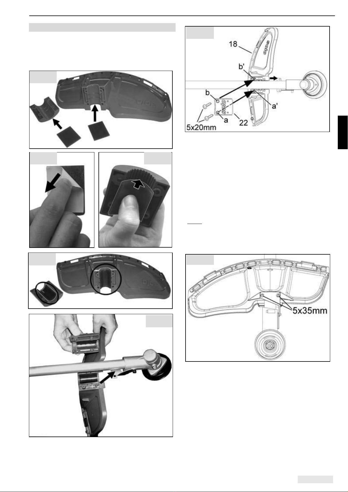
- Use a correct operating mode (see Chapter 7.2 Correct brushcutter operation").
- Use the power tool at lowest possible noise and exhaust levels. Only open the throttle when working, do not let
the engine run unnecessarily. Please note that noise also impacts on the environment. Observe the quiet times
that can vary from place to place.
- Never use blunt cutters and avoid uncontrolled contact of the cutter with debris. Otherwise there will be an
increased risk of the equipment kicking, which could throw the entire machine around. As a result, the operator
could be subjected to involuntary movements, which could lead to serious injury or death.
•Stop the engine if you notice a difference in the operating characteristics of the brushcutter.
•Due to the centrifugal clutch, the cutters will run on for a short time, even if you release the throttle. Ensure the
cutter has come to a full stop before storing the machine.
•Always stop the engine before any contact with the cutter – even when clearing a blockage or if cutters have
become jammed – wait until the cutter has stopped and remove the spark plug cap.
•Never touch the exhaust or the silencer; as long as they are still hot, there is a risk of burns!
•Never work with a defective or missing silencer. There is a hazard of hearing damage and burning!
First Aid
A first aid box should always be available on-site. Immediately replace any materials you have used:
Note:
Over exposing persons with circulatory problems to vibrations can lead to damage to their nervous system or blood
vessels. The following systems may occur from vibrations to fingers, hands or the wrists: Numbness, itching, pain,
twinges, changes to the colour of the skin or the skin itself. Seek medical advice if you experience any of these
symptoms.
1.8 Maintenance and repairs
The power tool must be serviced on a regular basis. Only perform maintenance work or repairs yourself if the work is
described in these operating instructions or in the separate operating instructions for the engine. All other work must
only be performed by an authorised workshop.
•Do not maintain, repair or store the machine near an open flame.
•Before cleaning, maintenance and repair work, always stop the engine first and pull the spark plug cap.
Exceptions: carburettor and idle adjustments.
•For any repairs only use original parts from the manufacturer.
•Do not modify, alter or change the machine as this may impact on the safe operation of the machine and may
lead to accidents and injuries!

Standard delivery; Control and function elements
ENGLISH 7
2. Standard delivery
•Brushcutter partially assembled; the following components are supplied separately and require assembly
•Handle subject to model and all parts required to complete the assembly
•Shoulder strap
•Shield, protective bar (line trimmer assembled) and all parts required to assemble the shield
•Cutting tool: (model-specific, for metal cutting blades this also includes a corresponding transport protector)
•All assembly parts required to fit the grass cutter blade and the nylon head (all models)
•Tools: combination spanner, retaining pin and screw driver
•These operating instructions and the separate engine operating instructions
3. Control and function elements
Brushcutter (engine Îmodel-specific)
Model with "loop" handle Model with "bike" handle
(128L, 135L) (128B, 135B)
135B
(for example)
128L
(for
example)
Fig. 1a 1 Stop-switch
2 Throttle lever
3 Throttle lock
5a "Loop" handle
5b "Bike" handle
12 Strap attachment
13 Anti-vibration system
14 Handle support
15 Quick acting tension
screw
17 Cutter
18 Shield
22 Retainer
Fig. 1b

Preparing the equipment for use
ENGLISH 8
4. Preparing the equipment for use
For shipping purposes, the brushcutter is partly
disassembled and has to be reassembled prior to
use.
Only use the brushcutter after it has been fully
assembled.
Ensure that the tank is fully drained before any
assembly, disassembly or modification.
4.1 Assembly of the handle
A) "Loop" handle for models 128Land 135L
(letter "L" in the model name)
Attach the "loop" handle approximately 5 cm - 30 cm
from the strap attachment according to your
preferred working position. The longer side of the
handle serves as a safety barrier and must therefore
always be on the side of the user:
•If you carry the brushcutter on the right hand side
of your body when working then the longer side of
the handle must face to the left.
•If, however, you prefer to carry the brushcutter on
the left hand side of your body when working (i.e.
if you are left-handed) then the longer side of the
handle must face to the right.
•Initially tighten the screws only lightly.
•Push the handle, in accordance with your body
size, into its optimum position.
•Then tighten the screws.
B) "Bike handle" for models 128B and 135B
(letter “B” in the model name)
•Remove quick release screw (15) with sleeve (19)
and wavy washer (20) from the handle support
(14)
•Take off the two half shells (a) from the handle
support.
•Position the two-handed "bike handle" (5) with the
two half shells (a) on the handle support (14).
•Insert quick release screw (15) with sleeve (19)
and wavy washer (20) into the handle support, but
only so far that the quick release mechanism can
still flip over when the handle is sitting tight. The
quick release mechanism can be flipped over to
the front or rear. If the handle is not quite tight yet,
tighten the quick release screw another half turn
and flip the mechanism to the opposite side.
•The r.h. side of handle should be fitted as near as
possible to the handle support..
•In order to adjust the handle to the perfect
position, flip up the quick release mechanism and
loosen the screw one turn if necessary.
•Adjust the handle and screw the quick release
screw (15) back in again, then flip the quick
release mechanism back over.
Note: You will have achieved an optimum
adjustment, if the centre of the power tool is at the
centre of your body. Your elbow should be slightly
angled in operating position.
Important: Always lead the brushcutter with the
bicycle handlebar on the r.h. side of the body!
Fig. 2b
Fig. 2a

Preparing the equipment for use
ENGLISH 9
4.2 Shield installation
When assembling the guard, the damping inserts
from the accessories pack must be fitted into the
guard and mounting bracket in accordance with
Figures 3a - 3e below.
•Position the brushcutter with the output shaft
facing downward.
•Raise the shaft tube and slide the guard (18) along
the underside of the shaft tube into the correct
position (it should reach a stop at the angular
gearbox).
•Lay down the shaft tube with the guard.
•First insert a 5 x 20 mm bolt through hole a to
tighten the retainer (22) on the guard. Then insert
the second 5 x 20 mm bolt through hole b,
tightening finger tight only at this stage.
(Note: The retainer has a raised part on the inside
near hole a. This allows the first bolt (which is
inserted through hole a) to be tightened straight onto
the block without any risk of the connection not being
straight.)
•Reposition the brushcutter with the output shaft
facing upward.
•Insert the two long 5 x 35 mm bolts through the
hole on the retaining bracket of the angular
gearbox and tighten the guard and the retainer.
The holes must line up exactly, so it may be
necessary to adjust the position of the guard first.
•To finish off, fully tighten the bolt in hole b.
Fig. 4a
Fig. 4b
Fig. 3a
Fig. 3d
Fig. 3b Fig. 3c
Fig. 3e

Preparing the equipment for use
ENGLISH 10
4.3 Cutter installation
Always switch off the engine, pull the spark plug cap
and wear protective gloves when fitting or replacing
the cutter!
Depending on your particular model, one of the
following cutting tools will already be provided as
standard equipment with your brushcutter. The
cutting tools described below are available as
genuine SOLO replacement parts which can be
obtained from specialist retailers and should be
installed as described below. Please refer to the
overview of approved accessories in chapter 9 for
more information.
A) Assembly of the 3-tooth brush cutting blade
and the 4-tooth grass cutting blade
•Position the brushcutter with the output shaft
facing upwards.
•Place the brush cutting blade on the pressure
piece (25). In order to centre the cutting blade, the
shoulder of the pressure piece must be located
exactly in the bore of the cutting blade.
•Fix the pressure washer (26).
•Place the nut protector (27) and turn safety nut
(28) onto the shaft.
Caution! Left hand thread - tighten counter
clockwise.
Take care that all parts are centered.
•Block the shaft with the stop pin (4) and tighten
nut.
It is imperative that the safety nut (28) is
replaced, if it has become loose due to
frequent rem oval and tightening.
Afterwards check that the cutting blade is securely
seated and that it is properly centred.
Transport protection for metal cutting blades
When you first purchase an approved metal cutting
blade which is not supplied together with the
brushcutter (see chapter 9 "Accessories"), you will
also need to purchase a corresponding transport
protector.
When the metal cutting blades are attached (4-tooth
grass cutting blade or 3-tooth brush cutting blade,
provided either as standard equipment with the
different models or purchased as accessories), the
transport protector must always be attached to cover
the blades when the device is being stored or
transported, or during work breaks during which the
engine is switched off.
•Position the transport protector with the
corresponding recess at one of the tips of the
metal cutting blade.
•Press the two tabs (a) on the transport protector
together to increase the internal diameter of the
transport protector.
•Lay the transport protector right over the cutting
tool. Position the inner shoulder (b) between the
metal cutting blade and the running disc.
•Open the two tabs again, and in doing so also
position the inner shoulder between the metal
cutting tool and the running disc at tab (c).
When restarting work, take the transport protector
back off by pressing the two tabs (a) together before
starting the engine.
Fig. 5
Fig. 6

Preparing the equipment for use
ENGLISH 11
B) Assembly of the nylon line head
When fitting a nylon line head, you will not need the
following components shown in Fig. 5:
Retaining nut (28) (caution: left-handed thread), nut
protector (27), pressure washer (26) and metal
cutting blade.
•Fit the anti-winding protection (30) (supplied with
the line head) after the pressure piece (25). The
side of the anti-winding protection labelled with
the number "870" faces the gearbox, so the edge
of the anti-winding protection overlaps the edge of
the bevel gearbox.
•Block the shaft with the pin (29).
•Screw on the line head by hand. Caution: left-
handed thread.
•Fit the protective bar (31) with assembled line
trimmer from underneath onto the guard. Bend
the protective bar slightly in the process.
Important: When using the line head, never
start the brushcutter without the protective bar
and the line trimmer assembled.
If the length of the line has been adjusted (see
chapter 74, "Adjusting the cutting line"), the line
trimmer will automatically cut the ends of the line to
the correct length during operation.
When using metal cutting blades, always work
without the protective bar fitted.
C) Assembly of the "Jet-Fit " cutting head
Insert the cutting line
into the main body of
the cutting head in
accordance with the
arrows on the main
body. Insert enough
line so that approx. 20
mm of the cutting line
protrudes from the
opening on the
opposite side.
Make sure that the
cutting teeth are
correctly aligned in the
direction of rotation.
Various washers are
supplied with the
cutting head.
For installation on this
type of brushcutter, use
exactly the washer
dimensions shown in
the illustration (outer
diameter, inner
diameter).
The lower washer with
an inner diameter of 16
mm must be positioned
around the splines on
the shaft.
Block the shaft with the pin (29) and tighten the nut
(28). Check that the cutting head is securely seated
and properly centred.
Fit the cover of the
cutting head in place,
turn it in the direction of
the arrow and tighten it
with the combination
wrench as shown in the
illustration until it
engages.
When using the "Jet-Fit-Flexiblade" cutting head,
always use the standard guard and the assembled
protective bar.
Cutting lines must not touch the guard during rotation.
If necessary, insert the cutting lines slightly further
into the main body of the cutting head. The line
trimmer which is assembled in the protective bar is
not suitable for cutting lines. ÎThe length of the
cutting lines needs to be manually adjusted to the
correct length.
To replace a cutting
line, pull the
protruding end back
out from the main
body in the direction
of the arrow (use
universal pliers if
necessary).
Fig. 7
Fig. 8c
Fig. 8b
Fig. 8d
Fig. 8e
Fig. 8a

Preparing the equipment for use; Fuelling
ENGLISH 12
4.4 Shoulder strap adjustment
Before commencing work, adjust the shoulder strap
and handle according to the operator’s body size.
A) Models with a "loop" handle (128L and 135L-
letter "L" in the model name)
Wear the single shoulder strap over the opposite
shoulder to the side on which you are carrying the
brushcutter. If you carry the brushcutter on your right
while working, wear the strap over your left shoulder.
If, however, you carry the brushcutter on your left
while working, wear the strap over your right
shoulder. Once the length of the strap has been
correctly adjusted the strap hook should be over your
hip. Hook the strap hook into the strap attachment on
the brushcutter.
Balance the brushcutter and attached cutting blade
so that the cutting tool hovers just above the ground
when your hands are off the attached brushcutter.
If the cutting tool hovers more than 10 cm above the
ground, secure the shoulder strap retainer nearer to
the motor.
If the cutter lies on the ground, secure the shoulder
strap retainer nearer the handle.
B) Models with a "bike" handle (128B and 135B -
letter "B" in the model name) – double shoulder
strap
The brushcutter has to be balanced after the hook
(Fig.1b, pos. 12) is placed in the strap hanger. To
balance the brushcutter the hook is hung in one of
the various fastening holes. Release the strap on the
respective hook.
The cutting tool must come to rest directly above the
ground (0 cm - 10 cm) when your hands are off the
attached brushcutter.
5. Fuelling
Always comply carefully with the specifications in
the separate operating instructions for the
engine.
5.1 Fuel information
A high performance two-stroke engine operated with
a petrol:oil mixture (petrol + oil = fuel mixture) or with
a special fuel mixture for two-stroke engines available
from specialists powers this machine. Unleaded
normal petrol can be used for the fuel mix.
Unsuitable petrol or deviations in the mixing ratio may
lead to serious engine damage!
Avoid direct skin contact with petrol and avoid
inhaling petrol fumes - health hazard!
Mixing ratio:
We recommend a mixture of 1:50 (2%) when using
our special 2-stroke oil "SOLO Professional 2-
stroke Engine Oil".
Order no.: 1-litre pouring bottle 0083105
Fuel mixture table
Oil in litres
Petrol in
litres SOLO 2T engine oil
2% (50 : 1)
1 0,020
5 0,100
10 0,200
Never store fuel mixture longer than 3 - 4 weeks.
5.2 Fuelling
While fuelling always follow all safety instructions and
take all safety precautions.
Handle fuel only with the engine turned off. Carefully
clean the area around the filler inlet. Place the
machine with the fuel inlet pointing upwards. Unscrew
the tank lid and fill the fuel mixture up to the lower
edge of the filler neck. Use a funnel with filter to
prevent tank contamination. After filling the tank
replace the tank lid and tighten firmly.
Fig. 9

Starting / Stopping the engine
ENGLISH 13
6. Starting / Stopping the engine
6.1 Startup settings on the engine
Precise details for your engine type can be found
in the separate engine operating instructions.
The Kawasaki engine of your new brushcutter is
already equipped with the Kawasaki easy start
technology (KAR).
Cold start adjustment:
•Move the Stop switch into operating position.
•Press the primer (a) to pump fuel into the
carburetor.
•Turn the cold-start-lever (b) clockwise in the left
position.
•Pull the starter handle, continue starting until the
engine runs. Operate the thottle control once to
reset the cold start position Îthe cold-start-lever
(b) jumps back to the normal position.
If the engine is warm (warm start) the cold-start-lever
(b) has to remain in the normal position.
We recommend the following procedure if the engine
is flooded in this way and it is difficult to start the
engine:
•Remove the spark plug and dry fuel mixture from
the electrodes.
•Move the throttle lever up to full throttle. Pull the
starter handle several times (with removed spark
plug) to clear the combustion chamber.
•Move the throttle lever down to idling position, refit
the spark plug, the plug cap and the plug cover.
•Start the engine with the part throttle stop set and
the choke lever set to the "open" position ( ).
6.2 Starting
Observe the safety instructions when starting.
Lay the brushcutter level and without obstructions on
the ground.
During starting, never stand or kneel on the shaft
tube, otherwise the shaft or the tube might be
damaged.
Take up a safe position, securely hold the machine
and ensure that the cutter does not touch any objects
or the ground.
Move the stop switch to the operating position.
Note: Under good conditions, the engine will already
start under idling throttle if it is at operating
temperature. (If a part throttle stop is set it will be
cancelled by operation of the throttle control even if
the engine is at standstill.)
Set the part throttle stop as described above for all
cold starts or if the engine fails to start with the
throttle lever in idling position..
The following instructions are aimed at increasing the
service life of the starter rope and of the starter
mechanism:
•Always pull the rope out in a straight line.
•Do not let the rope drag across the edge of the
rope eyelet.
•Do not pull rope all the way out - risk of the rope
breaking.
•Always manually guide the rope back into its start
position with your hand on the starter grip - do not
let it retract on its own.
A specialist can replace a damaged starter rope.
6.3 Turning off the engine:
Release the throttle and push the stop switch to
”STOP”.
Important: Due to the centrifugal clutch, the cutter
will run on for a short time, even if you release the
throttle. Ensure the cutter has come to a full standstill
before storing the machine.
Fig. 11
Fig. 10

Using your brushcutter
ENGLISH 14
7. Using your brushcutter
7.1 Scope of Application
Only use brushcutters equipped with a nylon head
(subject to model) for cutting grass – particularly
suitable around obstacles - and for trimming light
weeds and wild growth near ground level. The nylon
head is particularly suitable for a soft cut, e.g. for
clean trimming around trees and posts.
Use brushcutters equipped with the grass cutter
blade (subject to model) only for cutting grass away
from obstacles and for cutting stronger weeds and
wild growth near ground level.
Only use brushcutters fitted with the 3-tooth brush
cutting blade (subject to model) for mowing grass,
light brush, reeds and uncultivated growth at ground
level.
Never use the brushcutter for any other purpose.
Using the cutting tools, which are available as
accessories and which are specified for certain
tasks, enable the brushcutter to be used for those
purposes specifically mentioned in the accessory
instructions. Also observe the safety instructions in
those accessory instructions.
Generally, use only the cutting tools authorised for
use with this brushcutter. Always fit the contact
shield specified for this brushcutter and cutting tool. If
in doubt, contact your local SOLO dealer.
7.2 Correct brushcutter operation
Observe the relevant safety instructions when using
the brushcutter.
The rotational direction of the cutting tool makes the
operation on the l.h. side of the cutting tool (from the
operator's viewpoint, subject to the brushcutter being
held correctly – section A) particularly free from
kicking. Therefore, always approach the area to be
cut from the right. This brings the l.h. side of the
cutting tool into contact with the material to be
trimmed first. Particularly when cutting tougher
growth (such as medium sized weeds and wild
growth), ensure that you do not "stab" the front of the
brushcutter into the material to be trimmed.
Approach the working area with the brushcutter set to
idle, and then switch to full throttle. Never leave the
engine running at high speed without applying a load.
Dip the tool from the r.h. side 2/3 into the material to
be trimmed. Then work the brushcutter lie a scythe,
i.e. by moving forward step by step, whilst cutting
from right to left.
Operate the brushcutter at full throttle to obtain an
optimum cutting result. Never operate with the clutch
in slipping range. Consequential damage through
excess loads or overheating is excluded from our
warranty.
Immediately stop the engine in case of noticeable
vibrations or when material has gathered around the
cutting tool or contact shield. Slow down the cutting
tool by pressing it onto the ground, until it has come
to a complete standstill. Pull the spark plug cap from
the plug, and clean the tool seat of all grass, roots
etc. Check the entire brushcutter for perfect condition.
7.3 Sharpening instruction for brush blade
(subject to model)
When dull, the cutter blade’s edges can be re-
sharpened on both sides with a flat file at an angle of
30°.
All cutting edges need to be filed back equally, if the
wear and tear is substantial, or if there are broken-off
cutting edges. It is necessary to check for imbalance
and if necessary, to make corrections by additional
filing. The sharpening angle is 30°.
Fig. 12
Fig. 13

Using your brushcutter
ENGLISH 15
7.4 Note on using the nylon line head
(available as accessory)
When using the nylon head, always ensure that you
operate only with the correct length of line. When the
contact shield is fitted, the line will always be
trimmed to the permissible length automatically (a
line trimming blade is fitted into the shield). There is
a high risk of injury, and the engine is subjected to
excessive loads leading to a risk of damage, if nylon
lines are left too long.
Important: When using the line head, never
start the brushcutter without the protective bar
and the line trimmer assembled.
Adjusting the cutting line
When using a semi-automatic nylon head:
(schematic diagram)
Whilst the brushcutter is running without load, but
with rotating nylon head, lightly push the nylon head
several times onto ground with growth cover. The
cutting line will be dispensed in stages. With each
action, approx. 30 mm line will be dispensed. The
line trimming blade will correct any excess length.
When the cutting line is fully spent, you can replace it
with line available
Ø 2,4 mm under part no. 6900942
or
Ø 3,0 mm part no. 6900974 (accessory).
Fig. 14

Operating and maintenance instructions
ENGLISH 16
8. Operating and maintenance instructions
8.1 General operating and maintenance
instructions
The maintenance and the repair of modern machines
as well as their safety-relevant assemblies require
qualified specialised training and a workshop
equipped with special tools and test equipment.
Consequently the manufacturer recommends that all
tasks not described in these operating instructions be
carried out by a specialised workshop. That
specialist has the required training, experience, and
equipment at his disposal, to provide you with the
most cost-effective solution for such work. He will
provide additional help in word and deed.
After a running-in time of app. 5 hours, all accessible
screws and nuts (except the carburettor adjusting
screws) must be checked for tightness and they must
be retightened, if required.
Check the cutter regularly and whenever you notice
any irregularities, or when the cutter/contact shield
becomes blocked. For this, switch off the engine and
wait until the cutter has come to a complete
standstill. Pull the spark plug cap, and remove grass,
debris, etc. from the cutter support. Immediately
replace blunt or damaged tools, even if they display
only small cracks – do a ”ping” test.
It is best to store the equipment in a dry, safe
location with a full fuel tank. There should be no
open flame or similar nearby. For longer periods
without using the equipment (longer than four
weeks), see chapter
“8.4 Shutdown and storage”.
8.2 Gearbox lubrication
To lubricate the bevel gear drive, use SOLO "Special
gearbox grease" (part no. 008318025). Check the
grease level weekly and top up, if required (approx.
every 20 - 50 hours).
(schematic diagram)
Remove the filler plug from the side of the gearbox. If
no grease is visible inside, top up with grease (top-up
quantity approx. 5 – 10 g).
Replace and tighten the filler plug.
Please note: Do not overfill with grease, as that may
lead to the gearbox overheating. Never fill the
gearbox casing to the top with grease.
Tip: If required, top up with a maximum of 5g grease.
It is preferable to check more frequently (e.g. before
you start working) whether grease is still visible.
Your SOLO dealer workshop is happy to help you in
case of doubt.
Fig. 15

Operating and maintenance instructions
ENGLISH 17
8.3 Engine components
When performing adjustments or maintenance work
on engine components, always carefully follow the
specifications in the separate operating instructions
for the engine. Only perform work which is actually
described in the instructions and which you feel able
to carry out. All other work must only be performed
by an authorised specialist workshop, who will also
be happy to assist with any queries.
The following work is the minimum level of work
which must be performed on a regular basis in
accordance with the specifications in the operating
instructions for the engine:
•Check the idling position and readjust the idling
stop screw as required.
No drive must be delivered to the cutting tool
when the engine is idling.
•Clean the air filter and check the filter element.
•Check the silencer before starting work and
before starting the engine to check it is in perfect
condition.
Never touch the silencer when it is hot.
•Check the spark plug to make sure that the
electrode gap is correct and the electrodes are
not excessively burned off.
•Check the fuel tank breather and the fuel filter.
8.4 Shutdown and storage
Preferably, store the equipment in a dry and secure
place with a full fuel tank. Open flames or similar
must not be nearby. Prevent unauthorised use –
particularly by children.
For stops longer than four weeks the following steps
should be carried out:
•Empty and clean the fuel tank at a well-ventilated
location.
•Start the engine with an empty fuel tank. Run the
engine until the carburettor is empty and the
engine stalls. Otherwise the carburettor nozzles
could become encrusted with residual fuel mixture
and make a subsequent start harder.
•Clean the power tool well (particularly the air intake
openings, the cylinder fins, the air filter and the fuel
filler area).
•Preferably, store the equipment in a dry and secure
place with a full fuel tank. Open flames or similar
must not be nearby. Prevent unauthorised access
– particularly by children.

Operating and maintenance instructions
ENGLISH 18
8.5 Scheduled maintenance
The following information is based on standard operating conditions.
For special conditions, such as prolonged daily use, the recommended
maintenance intervals should be reduced accordingly.
after the first 5 hours
before starting work
weekly
after every 50 hours
after every 100 hours
as required
before the start of the mowing
season, or once per year
Check idling speed X
Carburettor
Adjust idling speed X
Clean X
Air filter
Replace X
Check the electrode gap and adjust, if required X X
Spark plug
Replace X X
Check X X
Gearbox lubricant
Top up X X X
Check X
Sharpen X
Metal cutting blades
model-specific / accessory
Replace X
Cooling air inlet Clean X XX
Cylinder fins Clean X X
Fuel tank Clean X X
Fuel filter Replace X
All accessible screws
(except for adjusting screws)
Retighten X XX
Controls
(stop switch, throttle lever,
half throttle detent, starter)
Check function X
Silencer Visual inspection X
Visual inspection X
Complete machine
Clean X X X
Implement all maintenance jobs regularly. If required, authorise a specialist service centre to maintain the
machine for you. The owner of the machine is responsible for:
•Any damage caused by a lack of maintenance, incorrect or late maintenance and repairs
•Consequential losses - including corrosion - from incorrect storage

Accessories
ENGLISH 19
9. Accessories
Via dealers, SOLO offers an extensive range of brushcutter accessories. Their use is limited to the particular
model to which it is allocated, together with its relevant protection. Orientate yourself on the following table and
check with your dealer.
Model
Accessory Protection Part no.
128L/B
135 L/B
2 nylon head semi-automatic M 10 x 1.25 LI
(grass, even around obstacles, light weeds)
Standard shield +
protective bar,
line trimming blade
69006515 XX
2 nylon head semi-automatic M 10 x 1.25 LI
(grass, even around obstacles, light weeds)
Standard shield +
protective bar,
line trimming blade
69006526 X X
Replacement line for nylon head 15m, Ø2.4 mm 6900942 XX
Spool of nylon cord 90 m, Ø2,4 mm 0063201 X X
Replacement line for nylon head 15m, Ø3.0 mm 6900974 X
Grass cutter blade 4 teeth, Ø230 mm
(grass, stronger weeds) Standard shield 6900948 X X
Brush blade 3 teeth Ø250 mm
(bushes, reeds, tough grass) Standard shield 6900947 XX
Transport protector for metal cutting blades up to
Ø250 mm 6073543 X X
Brush blade 3 teeth Ø300 mm
(bushes, reeds, tough grass) Standard shield 6900943 X
Transport protector for metal cutting blades up to
Ø300 mm 6073549 X
2-line-Cutter head "Jet-Fit"
(bushes, reeds, tough grass, branches up to 20mm)
Standard shield +
protective bar,
line trimming blade
6900160 XX
Replacement line for "Jet-Fit" cutter head
2.5 mm x 260 mm 50 pcs. 6900166 X X
Replacement line for "Jet-Fit" cutter head
2,5 mm x 53 m 6900175 XX
High performance gearbox grease 008318025 X X
SOLO 2T engine oil 100 ml 0083103 XX
SOLO 2T engine oil 1 l 0083104 X X
SOLO 2T engine oil, in a metering bottle 1 l 0083105 XX
SOLO face/ear protection pack 993901002 X X
SOLO forest and countryside work jacket EN 340 99303000 + size (2[s] - 6[xxl]) XX
SOLO Outdoor Knee-breeches 9902095 + size X X
SOLO Outdoor dungarees 9902094 + size X X
SOLO leather forest boots 9930510 + size (36 - 48) X X
Gloves SOLO Fit 9939012 + size X X

Specification
ENGLISH 20
10. Specification
Brushcutter 128L 128B 135L 135B
Engine type Kawasaki single cylinder two-stroke engine
Engine capacity cm326,3 34,4
Bore / stroke mm 34 x 29 37 x 32
Engine power kW at rpm 1,2 / 7000 1,47 / 7000
Fuel tank capacity l 0,6 0,7
Fuel consumption at max. power
(ISO 7293) kg/h
0,56
0,70
Specific consumption at max. power
(ISO 7293) g/kWh
466
480
Clutch engagement speed rpm 3760 3760
Gear reduction 1,23:1
Shaft tube - connection Ø mm
Drive shaft Ø mm
Star serration
24
7
7 teeth
28
8
9 teeth
Dimensions cm
Height
Width
Length
28
38
185
50
67
185
29
38
186
51
67
186
Weight kg
w/o shield and cutter
5,7 6,2 6,6 7,1
In determining the following values regarding the acceleration of vibrations and sound, the different operating
conditions were weighted in accordance with the current standards.
Weighted effective acceleration ahv,eq
(DIN ISO 22867)
Handle r.h. side / handle l.h. side
Nylon head m/s2
Brush blade 3-tooth m/s2
Grass cutter blade 4 teeth m/s2
Cutter head "Jet-Fit" m/s2
2,2 / 5,8
4,7 / 5,2
4,8 / 6,1
2,8 / 4,8
4,9 / 5,7
4,0 / 4,8
3,8 / 5,8
2,9 / 4,6
3,3 / 6,0
4,4 / 5,0
5,8 / 6,8
4,5 / 6,0
3,6 / 4,8
3,5 / 4,2
3,3 / 4,0
3,6 / 4,5
Sound pressure level LPeq (EN ISO 22868)
Nylon head dB(A)
Brush blade 3-tooth dB(A)
Grass cutter blade 4 teeth dB(A)
Cutter head "Jet-Fit" dB(A)
93
90
90
94
93
90
90
94
95
93
93
95
95
93
93
95
Sound power level LWeq (EN ISO 22868)
Nylon head dB(A)
Brush blade 3-tooth dB(A)
Grass cutter blade 4 teeth dB(A)
Cutter head "Jet-Fit" dB(A)
102
101
101
102
102
101
101
102
105
105
105
105
105
105
105
105
Other manuals for 128L
2
This manual suits for next models
3
Table of contents
Other Solo Brush Cutter manuals