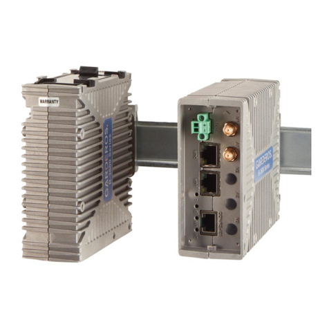
Garderos R-3700 Series User manual

© 2019 Garderos GmbH 1/21
Operating Manual
Garderos R-3700 Series
Ruggedized router (IP42) with
2 RJ-45 10/100/1000 BaseT Ethernet interfaces
1 RJ-45 RS-232 serial interface (management) + RS-485
1 DSUB-9 female RS-232 (full)*
1 or 2 integrated WWAN modems (2/3G, 2/3/4G, CDMA)*
1 or 2 WLAN 802.11n a/b/g/ac*
* optional

© 2019 Garderos GmbH 2/21
1 Safety instructions
Do not open the casing. Warranty shall be void if the warranty seal has been
tampered with.
Don't use or install the device in an explosive atmosphere!
Don't touch any contacts with metallic or pointed items.
This device has no power switch. Please disconnect the power before any
operational work.
In case of any damage to the device, it must not be put into operation.
Do not install the device during a thunderstorm!
Protect the device from heat sources and direct sunlight.
Protect the device from aggressive fluids and vapors.
The router emits electromagnetic waves. To prevent other devices from
being disturbed and to protect other people, install the router only as
described in this document and make sure to comply with safety distances.
Unauthorized persons must not get nearer than 60cm to the
GSM/UMTS/LTE antennas.
Unauthorized persons must not get nearer than 7cm to the WLAN
antennas.
Depending on the router type, the antenna and configured networks the
safety distances may be smaller. Use the calculations in the Annex to
calculate the minimum safety distance of your router.
Remove the power connector before performing any maintenance or
cleaning work near to the antennas or directly at the router.
Read these safety instructions before handling or installing
the device.
Risk of burns! The device can operate in surroundings of
more than 70 °C, so the surface can get very hot. Install the
router inaccessible for unauthorized personnel. Before
touching the router, remove the power supply and wait for
10 minutes for the router to cool down or wear protective
gloves.

© 2019 Garderos GmbH 3/21
2 General information
2.1 Router type
The Garderos R-3700 routers are available as several different models with optional
WLAN, 2G/3G/4G and CDMA interfaces. This document is a general description for
the following router types:
Type
Eth.
RS-232
(Mgmt.)
RS-232
RS-485
WLAN
2/3G
2/3/4G
CDMA
R-3701
2
1
(opt.)
1
1
R-3703
2
1
1
2
R-3707
2
1
(opt.)
1
R-3721
2
1
1
1
1
R-3722
2
1
1
1
1
R-3723
2
1
1
2
1
R-3724
2
1
1
2
1
R-3727
2
1
(opt.)
1
1
R-3728
2
1
(opt.)
1
1
R-3741
2
1
1
1
1
1
R-3742
2
1
1
1
1
1
R-3745
2
1
1
1
2
R-3747
2
1
1
1
1
R-3748
2
1
1
1
1
R-3749
2
1
1
2
R-3751
2
1
1
1
1
1
R-3752
2
1
1
1
2
R-3755
2
1
1
1
2
R-3757
2
1
1
1
1
R-3758
2
1
1
2
R-3759
2
1
1
2
R-3771
2
1
1
1
1
R-3773
2
1
1
2
1
R-3777
2
1
(opt.)
1
1
The router type can be identified by the serial number of the router. The type is coded
into the first 5 characters of the serial number.
2.2 Included in delivery of Garderos R-3700
Standard scope:
Garderos R-3700 router
Phoenix 2-pin power connector and grounding kit
Optional accessories:
Antennas ( 2G/3G/4G, CDMA)
Antenna connector cables and adapters
Industrial grade power supply
Serial cables
Holding angle and additional DIN rail clip
Please check the contents of the package after receipt.

© 2019 Garderos GmbH 4/21
3 Hardware
3.1 Installation
The Garderos R-3700 has 2 options for mounting.
3.1.1 Mounting on integrated DIN rail mounting clip
Mount the router on a DIN rail as shown in the following drawing. Insert the upper
metal hook to the DIN rail first, and then push the plastic holder into the bottom part
of the DIN rail until it clicks in (see picture). The IP protection in this position is IP 41.
For unmounting push the router up, then remove it from the top of the DIN rail first.

© 2019 Garderos GmbH 5/21
3.1.2 Mounting for IP42 ingress protection
Using a DIN rail clip the router can be mounted with the connector side down. The
DIN rail clip will be attached to the router using two M4 screws. The IP protection in
this position is IP 42. Insert the upper part of the clip to the DIN rail, then push the
router down and insert the DIN rail clip to the rail on the lower part.
For unmounting push the router down and remove the lower part of the clip from the
DIN rail first.

© 2019 Garderos GmbH 6/21
3.1.3 Mounting with holding angle
Using an additional holding angle, the R-3700 can be mounted on a DIN rail for IP42
ingress protection, as shown in the following image:
3.1.4 Grounding
Grounding is not required for router operation but it improves the EMI characteristics
and is mandatory to comply with the standard IEC 61850-3. For grounding attach a
1.5mm² ground cable with a 0.8 x 2.8mm flat connector to the spade connector on
the R-3700 router as shown in the following picture.

© 2019 Garderos GmbH 7/21
3.2 Status LEDs
The Garderos R-3700 has 8 LEDs on the front, showing its operational status. All
LEDs, except from the Ethernet LEDs that are integrated into the RJ-45 Ethernet
sockets, are clearly marked on the casing:
P (green) Shows the status of the router’s power supply and is lit
during the entire period of operation.
S (green) Shows the current state of the router operating system.
The LED blinks during fetching and executing the router
configuration and is permanently lit when the configuration
of the device has been completed.
W1 (green) Depending on the type of the WWAN link this LED signals
the state of the link. The LED is off when no WWAN
connection is active and is lit while at least 1 WWAN
connection is active.
W2 (green) Is lit when the integrated WLAN interface is active.
Eth link (green) Is lit when an Ethernet link was detected.
Eth activity (orange) Blinks during Ethernet activity.
In normal operation mode the LEDs Power and Router Status are on, as well as the
green LEDs of all connected Ethernet ports.

© 2019 Garderos GmbH 8/21
3.3 Connectors
Depending on the type, the Garderos R-3700 routers have different connectors on
the front. All possible connectors are described below; the image shows the front
panel of an R-3728 with an optional RS-232 DSUB9 connector as an example. The
R-3700 routers have 2 SIM card slots on the back:
+ DC-Power connection. + (VCC) and –(0V/GND) are marked on the
casing.
CON/RS-485 RJ-45 jack for RS-232 serial console (Settings: 115200 / 8 / N /
1 / none) and RS-485 half duplex serial interface for connection
to industrial components.
eth0 RJ-45 jack for 10/100/1000 BaseT Ethernet
eth1 RJ-45 jack for 10/100/1000 BaseT Ethernet
M1 Main 1 antenna connector. See 3.3.3 for description.
A1 Auxiliary 1 antenna connector. See 3.3.3 for description.
M2 Main 2 antenna connector. See 3.3.3 for description.
A2 Auxiliary 2 antenna connector. See 3.3.3 for description.
M3 Main 3 antenna connector. See 3.3.3 for description.
RS-232 Optional: RS-232 connector.
Select an antenna for the correct band to get the best performance
on the network. Depending on the router type the WWAN supports
different frequencies. WWAN capabilities can be shown by the
command „show hardware wwan wwan0 information”.
See below for more information about login and command line
interface.

© 2019 Garderos GmbH 9/21
3.3.1 DC power connection
GND and VCC are marked. The allowed power range is 12-60V DC. Make sure to
correctly connect 0V/GND (-) and VCC (+) to power as marked on the front plate.
The router supports voltage levels up to +72VDC. When using higher input voltages,
the router may be damaged.
3.3.2 CON/RS-485
The RJ-45 connector’s pins are assigned to an RS-232 serial console and an RS-485
half duplex industrial serial interface. Pin assignment is:
PIN no.
Description
1
RS-232 console port RTS
2
RS-485 half duplex B
3
RS-232 console port TX
4
GND
5
GND
6
RS-232 console port RX
7
RS-485 half duplex A
8
RS-232 console port CTS
Serial cables can be ordered from Garderos.
3.3.3 Antenna connectors
Depending on the router type the antenna connectors M1, A1, M2, A2 and M3 are
used for different antenna connections, e.g. a 4G or a WiFi card, or they do not exist
on the router. The connectors are always SMA female for WWAN antennas and RP-
SMA for WiFi antennas. Login to the router and use the command:
R3700# show hardware connector
to show the assignment of the antenna connectors.
3.3.4 Optional RS-232 connector
The R-3700 series routers can be equipped with an additional fully allocated DSUB-9
connector for RS-232. This must be ordered as a special option. The DSUB-9 socket
is allocated in the following way:
PIN no.
Description
1
RS-232 DCD, data carrier detect
2
RS-232 TX, transmit data
3
RS-232 RX, receive data
4
RS-232 DSR, data set ready
5
Ground (GND)
6
RS-232 DTR, data terminal ready
7
RS-232 CTS, clear to send
8
RS-232 RTS, request to send
9
RS-232 RI, ring indicator

© 2019 Garderos GmbH 10/21
4 Software
The Garderos R-3700 routers run the Garderos Router Software (GRS) operating
system.
GRS provides the following functions:
Router operating system
Automatic management of the configuration:
Local configuration (startup configuration) to configure the router locally.
Remote configuration that can be downloaded from a web server for
central configuration management.
Interfaces to other systems via APIs:
HTTPS Configuration API
RADIUS authentication
NTP
SNMP
…
The GRS documentation is available online at:
https://www.garderos.com/techsup
Username and password for login to the support web are available from your
Garderos sales representative.
The documentation contains a detailed description of all GRS features. This
operating manual is limited to the basic steps for starting the router so that it can be
commissioned.

© 2019 Garderos GmbH 11/21
5 Commissioning
5.1 Installation
Connect the antennas before powering on the router. Connect antennas at least to
the M1, M2 and M3 connectors of the wireless interfaces which will be used. Ethernet
cables can be connected / disconnected at any time.
5.2 Handling of the SIM-card
Insert and remove SIM cards from the router only when the power is disconnected.
5.2.1 Removing a SIM card tray
The R-3700 router has 2 SIM card slots for Mini-SIM format. For routers with 1
WWAN modem (e.g. R-3728) the SIM card must always be inserted into slot “SIM 1”,
which is intended for the modem “wwan0”. For routers with 2 WWAN modems (e.g.
R-3757) the SIM card for the WWAN modem called “wwan0” must be inserted into
“SIM 1”, the SIM card for the modem “wwan1” into slot “SIM 2”.
To access the SIM-card slots remove the DIN Rail mounting kit by pushing it to the
top. Always put back the DIN rail mounting kit after inserting the SIM-card to prevent
the SIM card from moving when the router is exposed to shock or vibration.
Remove the DIN rail mounting kit by pushing the safety lock to the left and pushing
the DIN rail mounting kit up at the same time, as shown in the picture.
Remove the SIM trays by pressing the yellow button with a screw driver.

© 2019 Garderos GmbH 12/21
5.2.2 Inserting the SIM-card
Insert the SIM card into the SIM tray and push the SIM tray back into the router as
shown in the following picture. Take care to correctly push the SIM tray into the SIM
card tray holder. The SIM card tray fits below the tray holder and may slip into the
router, if not put into the right position.
Put back the DIN rail mounting kit after that into the initial position.
5.3 Powering up the router
This device has no power switch. To power it on, just connect DC power (12-60V) to
the router.
Before starting the R-3700 an antenna
must be connected to the M1 connector
for models containing a WWAN modem,
otherwise the router may be damaged.
Remove the WWAN settings of the router before inserting a new
SIM card. Otherwise the router might try to establish the WWAN
connection with the previous settings, and an incorrect PIN might
cause the SIM-card to be locked.
Only insert/remove the SIM-card when the router is powered off!
Use thermo resistant Mini-SIM-cards for up to 80°C (ask your
cellular operator for industrial SIM-cards).
Connect VCC to + and 0V/GND to –as
marked on the front plate. Otherwise the
router might be damaged!

© 2019 Garderos GmbH 13/21
The LEDs (see chapter 3.2) show the operational mode of the device:
P Shows the status of the power supply and is lit during the entire
period of operation.
SShows the current state of the router operating system. The
LED blinks during fetching and executing the router
configuration and is permanently lit when the configuration of
the router has been completed.
W1 Is lit when at least 1 WWAN interface is active.
W2 Is lit when at least 1 WLAN interface is active.
5.4 Login
The Garderos R-3700 can be managed via a serial console. Connect your computer
to the router’s CON/RS-485 port using an RJ-45 serial console cable. Use the
following settings:
Bits per second
115200
Data bits
8
Parity
N
Stop
1
Flow control
None
Log in with the following credentials:
User name
root
Password
g42pnuMN
Find online documentation about initial configuration of the factory default Garderos
router at https://www.garderos.com/techsup in the chapter “Getting Started”. The
online documentation also contains detailed descriptions for more than 600
configuration parameters.

© 2019 Garderos GmbH 14/21
6 Annex
6.1 Technical Data
Dimensions (WxHxD)
44x105x126mm die cast aluminum
Weight
~0.45kg
Input voltage
12-60VDC
Power consumption
~4-12W
Operating temperature range
-40° to +75°C *)
Transport temperature range
Same as operating temperature range.
Storage temperature range
Same as operating temperature range.
WWAN (optional)
2G, 3G, 4G, CDMA (see datasheet for details)
Network interfaces
2 * RJ-45, 10/100/1000 BaseT Ethernet, autosensing, auto-MDI-X
WLAN (optional)
802.11ac a/b/g/n, 802.11 b/g/n
Serial ports
1 * RS-232 (mgmt), 1* RS-485, 1* RS-232 (optional)
Ingress protection
IP42
IEC protection class
3
Conformity
CE, FCC, 61850-3 (criteria for EMI immunity), RoHS
*) Max. temperature range. The temperature range may differ depending on the router variant.

© 2019 Garderos GmbH 15/21
6.2 WiFi radio settings
6.2.1 TX-power
The Garderos R-3700 uses the unregulated bands in the 2.4GHz and 5.5GHz range.
Depending on the country the maximum radiated power is limited by law to e.g.
100mW (20dBm) in Germany and 400mW (26dBm) in the US. By default the
Garderos routers are configured to comply with the German regulatory domain (DE).
The radiated power also depends on the antenna. To comply with the regulatory
limitations, the maximum radiated power must be configured in the R-3700 for the
antenna used with the router.
By default the Garderos R-3700 router will set the radiated power lower than 100mW
(20dBm) for both bands, meaning that it complies with all restrictions when being
used together with an antenna without gain. When using an antenna with a gain, the
power may need to be reduced in the configuration file.
To change the WLAN TX-power see the online documentation for the configuration
parameter:
hardware.wifi.*.tx-power
The following calculation shows how to calculate the TX-power that must be
configured in the router to comply with the regulatory restrictions.
Calculate the total antenna gain. The antenna gain consists of:
Losses inside the router. This is a static value of -0.3dB.
Antenna gain taken from the data sheet of the antenna.
Optional: Losses by extension cables.
Total antenna gain = -0.3dB + Antenna gain + Losses
The maximum value for the TX-power that can be configured on the router to
stay inside the regulatory limitations is calculated from:
Maximum output power allowed in the regulatory domain, e.g. 20dBm for
DE.
The total antenna gain.
tx-power max = 20dBm –Total antenna gain
Example:
Static value for losses in the router: -0.3dB
Antenna has a gain of 4dBi in the configured band 2.4GHz (channel 1-14).
No extension cable.
Regulatory domain Germany (DE) allows max. 20dBm output power.
The TX-power must be set to a value less or equal 16dBm.

© 2019 Garderos GmbH 16/21
tx-power max = 20dBm –(-0.3dB + 4dBi + 0dB) = 16.3dBm
Calculate maximum TX-power as described above and round down the value. Set
the TX-power on the router to that value to stay in the regulatory limits (16dBm in the
example above).
6.2.2 Safety distance
The router’s antennas should be installed in such a way that they are not accessible
for unauthorized persons. The following tables show the minimum safety distance
based on the harmonized EU standards EN 50385:2017 and EN 50383:2010, taking
into account the reference values of the Council recommendations 1999/519/EG:
Calculate the output power on the antenna from the configured TX-power on the
router and the total antenna gain:
Output power = Configured tx-power + Total antenna gain
Output power for the example above:
Output power = 16dBm + (-0.3dB + 4dBi + 0dB) = 19.7dBm
Round up the value (20dBm) and select the safety distance from the table below.
2.4GHz 5.5GHz
Output power
Safety dist.
Output power
Safety dist.
18dBi
2.2cm
18dBi
2.2cm
20dBi
2.8cm
20dBi
2.8cm
22dBi
3.6cm
22dBi
3.6cm
24dBi
4.5cm
24dBi
4.5cm
26dBi
5.7cm
26dBi
5.7cm
28dBi
7.2cm
28dBi
7.2cm
The default value for tx-power is set to 20dBm. If an antenna
with gain is used, the value must be set to a value from the
table above, to comply with the regulatory limitations. It is the
operator’s responsibility to comply with the regulatory
limitations.

© 2019 Garderos GmbH 17/21
6.3 WWAN radio settings
Based on the harmonized EU standards EN 50385:2017 and EN 50383:2010, taking
into account the reference values of the Council recommendations 1999/519/EG the
safety distances for the 2G/3G/4G antennas can be calculated. The calculation is
based on the output power of the router and the gain and losses inside the antenna
and extension cables.
The R-3700 routers are delivered with different WWAN modems depending on the
router type. To find out the modem type used in the router, login to the router, then
execute the command:
router# show hardware wwan
This command also shows the bands that the modem is active in.
The following tables show the maximum output power for all WWAN modems
depending on the supported technology:
WWAN modem type
2G
3G
4G
CDMA450
EG25-G
35dBm
25dBm
25dBm
HE910-D
33.5dBm
24dBm
LE910-EU V2
33.5dBm
24.5dBm
24dBm
LE910-EU1
33.5dBm
24dBm
LE910-EUG
33.5dBm
25dBm
25dBm
MC7430
24dBm
24dBm
MPN200
25dBm
WPD-600N
23dBm
The gain and loss in the antenna and antenna cables also need to be taken into
account to get the output power relevant for the safety distance.
Calculate the total output power on the antenna. This value is calculated from:
Output power for each technology supported by the WWAN modem taken
from the table above.
Losses inside the router. This is a static value of -0.3dB.
Antenna gain taken from the data sheet of the antenna. If the gain depends on
the frequency, the calculation has to be done for each different gain.
Optional: Losses by extension cables.
Output power = Modem power -0.3dB + Antenna gain + Losses
Example:
Output power of the LE910-EU1 WWAN modem for 2G (GSM) is 33.5dBm, for
4G (LTE) it is 24dBm.
Losses inside the router are -0.3dB.
Antenna has a gain of 4dBi in all frequencies for 2G and 4G.
No extension cable.
Output power4G = 24dBm -0.3dB + 4dBi = 26.7dBi
Output power2G = 33.5dBm -0.3dB + 4dBi = 37.2dBi

© 2019 Garderos GmbH 18/21
6.3.1 Safety distance per frequency
The safety distance depends on the output power and the frequency. Generally the
safety distance needs to be higher for lower frequencies.
You can see the frequencies supported by the WWAN modem by using the
command:
router# show hardware wwan
The following table shows the frequencies for the supported bands:
2G (GSM)
3G (UMTS)
4G (LTE)
Band
Frequency
Band
Frequency
Band
Frequency
GSM-850
850 MHz
B1
2100 MHz
B1
2100 MHz
GSM-E-900
900 MHz
B2
1900 MHz
B3
1800 MHz
DCS-1800
1800 MHz
B4
1700 MHz
B5
850 MHz
PCS-1900
1900 MHz
B5
850 MHz
B7
2600 MHz
B6
800 MHz
B8
900 MHz
B8
900 MHz
B18
850 MHz
B9
1700 MHz
B19
850 MHz
B19
800 MHz
B20
800 MHz
B21
1500 MHz
B28
700 MHz
B31
450 MHz
B38
2600 MHz
CDMA 450
B39
1900 MHz
Band
Frequency
B40
2300 MHz
450
450 MHz
B41
2500 MHz
To find out the correct safety distance, first calculate the output power for your
router/antenna setup for all frequencies. Then read the safety distances from the
following table for each of them. Round up the output power and round down the
frequency to one of the values from the table. The highest value shown in the table is
the safety distance that you should comply to:
Output
power
450MHz
700MHz
800MHz
900MHz
1500MHz
1800MHz
>=2GHz
20dBi
6.0cm
4.8cm
4.5cm
4.2cm
3.3cm
3.0cm
2.9cm
22dBi
7.5cm
6.0cm
5.6cm
5.3cm
4.1cm
3.8cm
3.6cm
24dBi
9.5cm
7.6cm
7.0cm
6.7cm
5.2cm
4.7cm
4.5cm
26dBi
11.9cm
9.6cm
8.9cm
8.4cm
6.5cm
6.0cm
5.7cm
28dBi
15.0cm
12.0cm
11.2cm
10.6cm
8.2cm
7.5cm
7.2cm
30dBi
18.8cm
15.1cm
14.1cm
13.3cm
10.2cm
9.4cm
9.0cm
32dBi
23.7cm
19.0cm
17.8cm
16.8cm
13.0cm
11.9cm
11.3cm
34dBi
29.8cm
23.9cm
22.4cm
21.0cm
16.3cm
14.9cm
14.3cm
36dBi
37.6cm
30.2cm
28.2cm
26.6cm
20.6cm
18.8cm
18.0cm
38dBi
47.2cm
37.9cm
35.4cm
33.4cm
25.9cm
23.6cm
22.6cm
40dBi
59.4cm
47.7cm
44.6cm
42.0cm
32.6cm
29.7cm
28.4cm
42dBi
74.8cm
60.0cm
56.1cm
52.9cm
41.0cm
37.4cm
35.8cm
44dBi
94.2cm
75.5cm
70.6cm
66.6cm
51.6cm
47.1cm
45.0cm

© 2019 Garderos GmbH 19/21
6.3.2 Safety distance per modem type
Based on the calculations from above a safe value can be taken from the table
below, if the gain of the antenna connected to the router is known.
Antenna
gain
EG25-G
HE910-D
LE910-EU V2
LE910-EU1
LE910-EUG
MC7430
MPN200
WPD-600N
-4dB
17.8cm
14.1cm
13.3cm
13.3cm
13.3cm
4.6cm
7.5cm
6.0cm
-2dB
22.4cm
17.8cm
16.8cm
16.8cm
16.8cm
6.0cm
9.5cm
7.5cm
0dB
28.2cm
22.4cm
21.0cm
21.0cm
21.0cm
7.6cm
11.9cm
9.5cm
2dB
35.4cm
28.2cm
26.6cm
26.6cm
26.6cm
9.6cm
15.0cm
11.9cm
4dB
44.6cm
35.4cm
33.4cm
33.4cm
33.4cm
12.0cm
18.8cm
15.0cm
6dB
56.1cm
44.6cm
42.0cm
42.0cm
42.0cm
15.1cm
23.7cm
18.8cm
This simplified calculation can only be used, if the antenna
gain is equal for all frequencies, or if the gain is higher for
lower frequencies. In that case choose the higher gain. This
table can not be used, if the gain of the antenna is higher for
the high frequencies!

© 2019 Garderos GmbH 20/21
6.4 Warranty
The conditions of warranty for the Garderos products are described in the Garderos
General Terms and Conditions in the section entitled „Warranty“.
6.5 Declaration of conformity
Garderos GmbH declares that the Garderos R-3700 product conforms to CE. The
complete statement of conformity can be downloaded at:
https://www.garderos.com/conformity
6.6 Disposal information
Please consider the following when disposing of the device:
This device must not be disposed together with household waste.
The Garderos R-3700 contains a CR-2032 battery, which must be
removed before disposal. The battery can be removed in the following
way:
Disconnect the device from the power supply.
Open the device by using a screw driver.
Remove the screws of the router main board by using a screw driver.
The battery is located in a battery holder on the back of the main board. Push
out the battery using a screw driver.
Dispose of the battery at an official collection point for batteries.
Now dispose of the device at an official collection point for electronic waste.
This manual suits for next models
24
Table of contents
Other Garderos Network Router manuals
Popular Network Router manuals by other brands

Alpine
Alpine KAC-001 installation manual

Asus
Asus RT-AC59U quick start guide

ZyXEL Communications
ZyXEL Communications Dimension GS-3012 Support notes

Cisco
Cisco Nexus 7000 Series Hardware Installation and Maintenance

ZyXEL Communications
ZyXEL Communications Prestige 623R-T user guide

NETGEAR
NETGEAR Orbi RBR20 quick reference