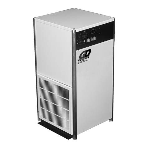
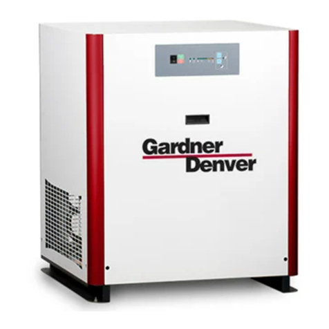
Gardner Denver VSS Series Troubleshooting guide

VSS SERIES REFRIGERATED DRYER
OPERATIONS & MAINTENANCE
300-1000 SCFM
PRINTED IN THE USA
2-2-645 REV A 10/00

2
TABLE OF CONTENTS
SECTION 1 General Information Pg 3-5
Model Numbers / Serial Numbers
Description of Operation
What is True Track Technology?
SECTION 2 Safety Instructions Pg 6-7
Handling
Installation
Operation
SECTION 3 Specifications Pg 8-10
Dimensions
Specifications
SECTION 4 Installation Pg 11-16
Location
Typical Installation
Piping and Connections
Recommended Filters
Electrical Connections
Drain Valve Time Settings
Remote Contact Hook-up
SECTION 5 Start-up and Shutdown Procedures Pg 17-18
VSS Control Panel Flowchart
SECTION 6 Maintenance and Repair Pg 19
SECTION 7 Troubleshooting Guide Pg 20-21
SECTION 8 Replacement Parts Pg 22-30
SECTION 9 Wiring Diagrams Pg 31-36
SECTION 10 Warranty / Claims Pg 37-40
Warranty
Claim Information
Procedures
What is covered?
Claim Form

3
SECTION 1 GENERAL INFORMATION
MODEL AND SERIAL NUMBER EXPLANATION
MODEL NUMBER CODING
SERIAL NUMBER CODING
SERIAL #TIME/DATE OF MANUFACTURE
V S S
FLOW (SCFM)
OPTIONS
VOLTAGE
A= AIR COOLED
W= WATER COOLED
300
400
500
650
800
1000
C= REMOTE OPERATION CONTACTS (48V MAX. INPUT)
F= PACKAGED FILTERS
P= IN/OUT AIR PRESSURE GAUGES
R= REFRIGERANT DISCHARGE PRESSURE GAUGE
S= REFRIGERANT SUCTION PRESSURE GAUGE
T= INLET/OUTLET TEMPERATURE GAUGES
3= 230/3/60
4= 460/3/60
5= 575/3/60

4
COMPRESSOR
CONDENSER
DESCRIPTION OF DRYER OPERATION
Operating principal - The dryers described in this manual operate on the same principal. A refrigeration unit reduces
the temperature of a chamber called an evaporator or heat exchanger through which warm, moist, compressed air is
passed. As the air is passed through the chamber, it is cooled causing moisture in the air to condense. The
condensate is collected and drained away via an automatic drain valve.
Air circuit - Warm, wet compressed air enters the dryer and passes through the air to air heat exchanger. Here, it is
cooled by cool, dry air leaving the evaporator. The pre-cooled air then enters the air to refrigerant heat exchanger
(evaporator ) where it is cooled to a temp of approximately 33-35 DEG F. Cooling in the evaporator causes water
vapor in the air to condense. Liquid water is entrained in the air stream where it enters a high efficiency water
separator and is removed from the system by means of an automatic drain.
Refrigerant circuit - Refrigerant (R-22) gas is pumped at high pressure by a compressor to an air or water cooled
condenser where it is cooled and condensed to a liquid form. The liquid is forced through a capillary tube or TXV
where the resulting pressure drop causes the boiling point of the refrigerant to drop. Low pressure liquid refrigerant
enters the evaporator where heat from the entering air is transferred causing it to boil and become a low pressure, cool
gas. A portion of the liquid may be bypassed through a liquid injection circuit that keeps the compressor cool under
conditions of high load and ambient temperatures. The low pressure gas is returned to the compressor, where it is re-
compressed and begins the cycle again.
Figure 1.2 Refrigeration Circuit
HOT GAS
VALVE
HEAT
EXCHANGER
AIR IN
AIR to AIR HEAT
EXCHANGER
AIR OUT
DRAIN

5
WHAT IS TRUE TRACK TECHNOLOGY ?
True Track Technology is a unique control system that conditions power to the compressor varying the refrigeration
system’s capacity to match the requirements for dry air.
As the load is reduced the compressor will be slowed until its output capacity matches the load. The speed of the compressor
(RPM) will vary directly with the changing need for refrigeration capacity, maintaining a consistent dew point. The power
consumption of the unit is directly proportional to the refrigeration capacity of the system, it is subsequently minimized. The fan
motor will be controlled in the same manner. This results in control of the heat transfer from the high temperature reservoir. Flow of
refrigerant in the system is dynamic. Changes in load, ambient, fan on/off all result in reactions by the refrigerant control devises as
they attempt to maintain a constant flow rate. These fluctuations in flow change the capacity of the system and consequently
change the measured output of the system, in this case the Dew Point of the outlet air.
Controlling the fan speed as opposed to cycling the fan reduces the fluctuation of the refrigerant flow improves the system
efficiency and stabilizes the output air dew point. The key to successfully applying True Track Technology to the dehumidification
process is in sensing the incoming load.
The load is indicated by :
The inlet flow rate
The inlet air temperature
The moisture content of the incoming air.
The refrigeration system indicators are:
The Evaporator Outlet temperature
The Low side pressure
This design monitors the Low-side pressure as the measure of the load on the refrigeration system. A pressure transducer
provides the control signal.
The controller maintains a fixed suction pressure over the dryers full flow range. The low-end frequency is set at the minimum
motor speed that provides
adequate oil distribution in the compressor.
The unit has three control modes:
Start-up Mode
•Controlled Acceleration
•The control gradually increases the input frequency and voltage until the motor is at full speed.
•The industry term for this is "SOFT START".
•It greatly reduces the current inrush, necessary to initiate rotation.
•It reduces winding temperatures and prolongs motor life.
Pressure Monitor
•The control monitors the input from the sensing device, decreasing motor speed to raise the pressure or increasing
the speed to lower the pressure.
•As the load on the refrigeration system increases, the pressure rises. The control reacts by increasing the frequency
and voltage to the motor. It speeds up improving its capacity and returning the pressure to the set point.
•As the load on the refrigeration system decreases, the pressure drops. The control reacts by decreasing the
frequency and voltage to the motor. It slows down reducing its capacity and returning the pressure to the set point.
Hot Gas Mode
•As the load on the refrigeration system continues to be reduced and the motor is slowed to the predetermined
minimum (RPM), the control switches to the Hot Gas Mode.
•The control locks the motor speed and initiates hot gas bypass.
•Injecting hot gas from the high side of the refrigeration system in to the low side prevents evaporator and drain
freeze-ups during extremely low demand.
•Increasing the load at this time will switch the control back into the pressure monitor mode and the unit will function
as described above.
All of this creates tight control of the evaporating pressure resulting in tight control of the output pressure dew point. Regulating the
refrigeration system capacity to match the load reduces the overall power consumption of the unit. Locking the hot gas by-pass out
during, the pressure monitor mode increases the full load capacity of the unit.
6
SECTION 2 SAFETY INSTRUCTIONS
2.1 HANDLING
PANELS,ETC. ARE NOT STRONG ENOUGH TO HANDLE THE WEIGHT OF THE DRYER. DO NOT LIFT THE
DRYER ANYWHERE EXCEPT THE DESIGNATED PLACES. PIPING, PERSONAL INJURY AND / OR EQUIPMENT
DAMAGE COULD RESULT.
ENSURE THAT ALL EQUIPMENT BEING USED TO LIFT THE DRYER IS CAPABLE OF LIFTING THE WEIGHT OF
THE DRYER. NYLON STRAPS AND SOFT RIGGING DEVICES SHOULD BE USED WHENEVER POSSIBLE TO
PROTECT THE COMPONENTS AND FINISH OF THE DRYER.
IF THE DRYER IS BEING TRANSPORTED OVERHEAD, BE SURE THAT ALL PERSONNEL ARE ALERTED AND
SAFETY PROCEDURES ARE FOLLOWED.
FIGURE 2.1.1 APPROVED LIFTING AND MOVING METHOD.
2.2 INSTALLATION
FAILURE TO FOLLOW THE SAFETY INSTRUCTIONS IN THIS SECTION COULD LEAD TO EQUIPMENT
DAMAGE, PERSONAL INJURY OR DEATH, OR BOTH. WILKERSON WILL NOT BE HELD LIABLE FOR FAILURE
TO FOLLOW THESE INSTRUCTIONS AND GUIDELINES.
Before starting or installing the dryer, be sure that all power to the unit is off, valves are shut, and the air circuit is at
atmospheric pressure. DO NOT remove, repair, or replace any component, control, filter, or part, while the air circuit is
energized or under pressure. Turn off the main to the dryer and de-pressurize the unit before starting installation or
maintenance procedures.
Pressure vessels need to be protected by safety relief valves. Refer to OSHA 1910.169 Paragraph B subparagraph (3)
and ASME Boiler and Pressure Vessel code, section VIII, Division 1, UG - 125 through UG - 136. Also check
government regulations, i.e. state and local codes.
When installing this equipment, comply with National Electric Code and any applicable federal, state, and local codes.
Make sure that all customer supplied wiring and electrical devices are properly sized to handle the electrical
requirements of the dryer.

7
MANUFACTURER WILL NOT BE RESPONSIBLE FOR DAMAGE TO EQUIPMENT AS A RESULT OF IMPROPER
WIRING OR ELECTRICAL INSTALLATION. IT IS THE CUSTOMERS RESPONSIBILITY TO ENSURE THAT THE
ELECTRICAL INSTALLATION IS CORRECT AND UP TO APPLICABLE CODES.
Read and understand the MSDS and first aid instructions for Refrigerant 22 (R-22)
2.3 OPERATION
DO NOT OPERATE THE DRYER ABOVE THE STATED WORKING PRESSURE (SEE SPECIFICATION TABLE).
FAILURE, INJURY AND EQUIPMENT DAMAGE COULD RESULT.
USE THIS DRYER FOR COMPRESSED AIR ONLY.
AIR FROM THIS DRYER IS NOT SUITABLE FOR BREATHING AIR SYSTEMS WITHOUT FURTHER FILTRATION
AND TREATMENT.

8
SECTION 3 SPECIFICATIONS
3.1 DIMENSIONS
VSS300-1000
BACK VIEW
aÄèÄÇàìò
aÄèÄÇàìòaÄèÄÇàìò
aÄèÄÇàìò dÄç
dÄçdÄç
dÄç qìÉ
qìÉqìÉ
qìÉ bàÖÖÑëÑçìàÄã
bàÖÖÑëÑçìàÄãbàÖÖÑëÑçìàÄã
bàÖÖÑëÑçìàÄã jÑçÜìá
jÑçÜìájÑçÜìá
jÑçÜìá uàÉìá
uàÉìáuàÉìá
uàÉìá fÑàÜáì
fÑàÜáìfÑàÜáì
fÑàÜáì gçMmîì
gçMmîìgçMmîì
gçMmîì bëÄàç
bëÄàçbëÄàç
bëÄàç uìL
uìLuìL
uìL
kmbcj
kmbcjkmbcj
kmbcj qadk
qadkqadk
qadk `rs
`rs`rs
`rs adk
adkadk
adk téãìÄÜÑ
téãìÄÜÑtéãìÄÜÑ
téãìÄÜÑ fn
fnfn
fn iñ
iñiñ
iñ nëÑííîëÑ
nëÑííîëÑnëÑííîëÑ
nëÑííîëÑ àçÇáÑí>
àçÇáÑí>àçÇáÑí>
àçÇáÑí> àçÇáÑí>
àçÇáÑí>àçÇáÑí>
àçÇáÑí> àçÇáÑí>
àçÇáÑí>àçÇáÑí>
àçÇáÑí> _
__
_`
``
`a
aa
ab
bb
bc
cc
cd
dd
de
ee
ef
ff
fg
gg
g aéççL>lnr
aéççL>lnraéççL>lnr
aéççL>lnr aéççL>lnr
aéççL>lnraéççL>lnr
aéççL>lnr ãÅ
ãÅãÅ
ãÅ
tqqQNN
tqqQNNtqqQNN
tqqQNN QNN
QNNQNN
QNN POTNN
POTNNPOTNN
POTNN OSST
OSSTOSST
OSST PQNKRTNMQMTN
PQNKRTNMQMTNPQNKRTNMQMTN
PQNKRTNMQMTN OLS
OLSOLS
OLS OLS
OLSOLS
OLS OLP
OLPOLP
OLP QQ
QQQQ
QQ PT
PTPT
PT RS
RSRS
RS PWLN
PWLNPWLN
PWLN QSLO
QSLOQSLO
QSLO QPLU
QPLUQPLU
QPLU OSLT
OSLTOSLT
OSLT çMÄ
çMÄçMÄ
çMÄ QLO
QLOQLO
QLO ONLR
ONLRONLR
ONLR QULV
QULVQULV
QULV POLW
POLWPOLW
POLW OKOMP@
OKOMP@OKOMP@
OKOMP@ OMR@
OMR@OMR@
OMR@ RRN
RRNRRN
RRN
tqqRNN
tqqRNNtqqRNN
tqqRNN RNN
RNNRNN
RNN PQRNN
PQRNNPQRNN
PQRNN OVTU
OVTUOVTU
OVTU PQNKRTNMQMTN
PQNKRTNMQMTNPQNKRTNMQMTN
PQNKRTNMQMTN PLN
PLNPLN
PLN OLT
OLTOLT
OLT P
PP
PQQ
QQQQ
QQ PT
PTPT
PT RS
RSRS
RS PWLN
PWLNPWLN
PWLN QSLO
QSLOQSLO
QSLO QPLU
QPLUQPLU
QPLU OSLT
OSLTOSLT
OSLT çMÄ
çMÄçMÄ
çMÄ QLO
QLOQLO
QLO ONLR
ONLRONLR
ONLR QULV
QULVQULV
QULV POLW
POLWPOLW
POLW P@
P@P@
P@ OMR@
OMR@OMR@
OMR@ RTN
RTNRTN
RTN
tqqSNN
tqqSNNtqqSNN
tqqSNN SNN
SNNSNN
SNN PVVNT
PVVNTPVVNT
PVVNT OVTU
OVTUOVTU
OVTU PQNKRTNMQMTN
PQNKRTNMQMTNPQNKRTNMQMTN
PQNKRTNMQMTN PLS
PLSPLS
PLS PLS
PLSPLS
PLS OLT
OLTOLT
OLT QQ
QQQQ
QQ PT
PTPT
PT RS
RSRS
RS PWLN
PWLNPWLN
PWLN QRLV
QRLVQRLV
QRLV QPLU
QPLUQPLU
QPLU OSLW
OSLWOSLW
OSLW çMÄ
çMÄçMÄ
çMÄ QLO
QLOQLO
QLO ONLO
ONLOONLO
ONLO QVLO
QVLOQVLO
QVLO POLW
POLWPOLW
POLW P@
P@P@
P@ OMR@
OMR@OMR@
OMR@ RVN
RVNRVN
RVN
tqqTSN
tqqTSNtqqTSN
tqqTSN TSN
TSNTSN
TSN RPNNN
RPNNNRPNNN
RPNNN PURP
PURPPURP
PURP PQNKRTNMQMTN
PQNKRTNMQMTNPQNKRTNMQMTN
PQNKRTNMQMTN QLN
QLNQLN
QLN QLU
QLUQLU
QLU PLV
PLVPLV
PLV QQ
QQQQ
QQ PT
PTPT
PT RS
RSRS
RS PWLN
PWLNPWLN
PWLN QRLV
QRLVQRLV
QRLV QPLU
QPLUQPLU
QPLU OSLW
OSLWOSLW
OSLW çMÄ
çMÄçMÄ
çMÄ QLO
QLOQLO
QLO ONLO
ONLOONLO
ONLO QVLO
QVLOQVLO
QVLO POLW
POLWPOLW
POLW P@
P@P@
P@ OMR@
OMR@OMR@
OMR@ SSN
SSNSSN
SSN
tqqVNN
tqqVNNtqqVNN
tqqVNN VNN
VNNVNN
VNN SRNNN
SRNNNSRNNN
SRNNN QSSV
QSSVQSSV
QSSV PQNKRTNMQMTN
PQNKRTNMQMTNPQNKRTNMQMTN
PQNKRTNMQMTN RLN
RLNRLN
RLN RLN
RLNRLN
RLN OLT
OLTOLT
OLT QT
QTQT
QT QN
QNQN
QN SOLT
SOLTSOLT
SOLT QQLS
QQLSQQLS
QQLS RNLP
RNLPRNLP
RNLP RTLO
RTLORTLO
RTLO ORLS
ORLSORLS
ORLS çMÄ
çMÄçMÄ
çMÄ QLO
QLOQLO
QLO VLQ
VLQVLQ
VLQ RQLV
RQLVRQLV
RQLV PSLW
PSLWPSLW
PSLW Q@
Q@Q@
Q@ OMR@
OMR@OMR@
OMR@ TNN
TNNTNN
TNN
tqqONNN
tqqONNNtqqONNN
tqqONNN ONNN
ONNNONNN
ONNN TUPNN
TUPNNTUPNN
TUPNN QSSV
QSSVQSSV
QSSV PQNKRTNMQMTN
PQNKRTNMQMTNPQNKRTNMQMTN
PQNKRTNMQMTN SLN
SLNSLN
SLN RLW
RLWRLW
RLW PLS
PLSPLS
PLS QT
QTQT
QT QN
QNQN
QN SOLT
SOLTSOLT
SOLT QQLS
QQLSQQLS
QQLS RNLP
RNLPRNLP
RNLP RTLO
RTLORTLO
RTLO ORLS
ORLSORLS
ORLS çMÄ
çMÄçMÄ
çMÄ QLO
QLOQLO
QLO VLQ
VLQVLQ
VLQ RQLV
RQLVRQLV
RQLV PSLW
PSLWPSLW
PSLW Q@
Q@Q@
Q@ OMR@
OMR@OMR@
OMR@ TPN
TPNTPN
TPN

9
SPECIFICATIONS
amknL amknL amknL kglgksk d_l>kmrmp
kmbcj djmu tmjr_ec pj_ jp_ fn agpasgr>_knq dj_>Fc_G
tqqQNN_KQ QNN>qadk PQNMTNMQ TLN SNLN NLWO OS NLPS
tqqQNN_KR QNN>qadk RTNMTNMQ>K>QVNMQMSN PLV PSLN OLVQ OS NLUN
tqqQNN_KS QNN>qadk SUSMTNMQ PLT PSLN OLVQ OS NLUN
tqqRNN_KQ RNN>qadk PQNMTNMQ TLV SNLN PLNN OS NLQN
tqqRNN_KR RNN>qadk RTNMTNMQ>K>QVNMQMSN QLP PSLN PLNN OS NLUN
tqqRNN_KS RNN>qadk SUSMTNMQ PLW PTLN PLUS OS NLUN
tqqSNN_KQ SNN>qadk PQNMTNMQ WLS UOLN PLSN OS NLUN
tqqSNN_KR SNN>qadk RTNMTNMQ>K>QVNMQMSN RLP QTLN PLSN OS NLUN
tqqSNN_KS SNN>qadk SUSMTNMQ QLP PTLN PLSN OS NLTN
tqqTSN_KQ TSN>qadk PQNMTNMQ ORLT WPLN QLNN PN OLRN
tqqTSN_KR TSN>qadk RTNMTNMQ>K>QVNMQMSN ULP RTLN QLNN OS NLUN
tqqTSN_KS TSN>qadk SUSMTNMQ SLP RRLN QLNN OS NLTN
tqqVNN_KQ VNN>qadk PQNMTNMQ OULN OPQLN SLNN PQ OLUN
tqqVNN_KR VNN>qadk RTNMTNMQ>K>QVNMQMSN VLS TPLN SLNN OS NLVN
tqqVNN_KS VNN>qadk SUSMTNMQ SLR SNLN SLNN OS NLTN
tqqONNN_KQ ONNN>qadk PQNMTNMQ OQLR OSTLN SLNN OW OLUN
tqqONNN_KR ONNN>qadk RTNMTNMQ>K>QVNMQMSN ONLQ UNLN TLNN OS NLVN
tqqONNN_KS ONNN>qadk SUSMTNMQ TLV SRLN TLNN OS NLTP
slgr k_v af_pecH qrb>mncp_rgle qrb>mncp_rgle qrb>mncp_rgle jmu>qgbc fgef>qgbc
kmbcj dj_ dsqc FpKPPG gljcr>_gp>npcqqL gljcr>_gp>rcknL _k`gclr>g_p>rcknL rcqr>npcqqL rcqr>npcqqL
tqqQNN_KQ U OS RV>éôL ONN>nqge ONNm>d ONNm>d OWN>nqge RNN>nqge
tqqQNN_KR QLS OS RV>éôL ONN>nqge ONNm>d ONNm>d OWN>nqge RNN>nqge
tqqQNN_KS PLT OS RV>éôL ONN>nqge ONNm>d ONNm>d OWN>nqge RNN>nqge
tqqRNN_KQ ULP OS TN>éôL ONN>nqge ONNm>d ONNm>d OWN>nqge RNN>nqge
tqqRNN_KR QLU OS TN>éôL ONN>nqge ONNm>d ONNm>d OWN>nqge RNN>nqge
tqqRNN_KS QLV OS TN>éôL ONN>nqge ONNm>d ONNm>d OWN>nqge RNN>nqge
tqqSNN_KQ ONLS OS TV>éôL ONN>nqge ONNm>d ONNm>d OWN>nqge RNN>nqge
tqqSNN_KR S OS TV>éôL ONN>nqge ONNm>d ONNm>d OWN>nqge RNN>nqge
tqqSNN_KS QLU OS TV>éôL ONN>nqge ONNm>d ONNm>d OWN>nqge RNN>nqge
tqqTSN_KQ OT PN ONN>éôL ONN>nqge ONNm>d ONNm>d OWN>nqge RNN>nqge
tqqTSN_KR V OS ONN>éôL ONN>nqge ONNm>d ONNm>d OWN>nqge RNN>nqge
tqqTSN_KS T OS ONN>éôL ONN>nqge ONNm>d ONNm>d OWN>nqge RNN>nqge
tqqVNN_KQ OW QN OPN>éôL ONN>nqge ONNm>d ONNm>d OWN>nqge RNN>nqge
tqqVNN_KR WLR PN OPN>éôL ONN>nqge ONNm>d ONNm>d OWN>nqge RNN>nqge
tqqVNN_KS TLS PN OPN>éôL ONN>nqge ONNm>d ONNm>d OWN>nqge RNN>nqge
tqqONNN_KQ OSLS PN OPN>éôL ONN>nqge ONNm>d ONNm>d OWN>nqge RNN>nqge
upbONNN_KR OOLQ PN OPN>éôL ONN>nqge ONNm>d ONNm>d OWN>nqge RNN>nqge
upbONNN_KS VLQ PN OPN>éôL ONN>nqge ONNm>d ONNm>d OWN>nqge RNN>nqge

10
SPECIFICATIONS
FOR DATA NOT LISTED CONSULT FACTORY
amknL amknL amknL kglgksk slgr
kmbcj djmu tmjr_ec pj_ jp_ fn agpasgr>_knq dj_
tqqQNNuKQ QNN>qadk PQNMTNMQ TLN SNLN NLWO OSLN ULN
tqqQNNuKR QNN>qadk RTNMTNMQ>K>QVNMQMSN PLV PSLN OLVQ OSLN QLS
tqqQNNuKS QNN>qadk SUSMTNMQ
tqqRNNuKQ RNN>qadk PQNMTNMQ
tqqRNNuKR RNN>qadk RTNMTNMQ>K>QVNMQMSN QLP PSLN PLNN OSLN QLU
tqqRNNuKS RNN>qadk SUSMTNMQ
tqqSNNuKQ SNN>qadk PQNMTNMQ WLS UOLN PLSN OSLN ONLS
tqqSNNuKR SNN>qadk RTNMTNMQ>K>QVNMQMSN RLP QTLN PLSN OSLN SLN
tqqSNNuKS SNN>qadk SUSMTNMQ RLT PTLN PLSN OSLN SLQ
tqqTSNuKQ TSN>qadk PQNMTNMQ
tqqTSNuKR TSN>qadk RTNMTNMQ>K>QVNMQMSN ULP RTLN QLNN OSLN VLN
tqqTSNuKS TSN>qadk SUSMTNMQ
tqqVNNuKQ VNN>qadk PQNMTNMQ
tqqVNNuKR VNN>qadk RTNMTNMQ>K>QVNMQMSN VLS TPLN SLNN OSLN WLR
tqqVNNuKS VNN>qadk SUSMTNMQ ONLQ UNLN TLNN OSLN ONLV
tqqONNNuKQ ONNN>qadk PQNMTNMQ
tqqONNNuKR ONNN>qadk RTNMTNMQ>K>QVNMQMSN ONLQ UNLN TLNN OSLN ONLV
tqqONNNuKS ONNN>qadk SUSMTNMQ
k_v af_pecH qrbL>mncp_rgle qrbL>mncp_rgle qrbL>mncp_rgle jmu>qgbc fgef>qgbc
kmbcj dsqc FpKPPG gljcr>_gp>npcqqL gljcr>_gp>rcknL _gp>rcknL rcqr>npcqqL rcqr>npcqqL
tqqQNNuKQ OS QN>éôL ONN>nqge ONNm>d ONNm>d OWN>nqge RNN>nqge
tqqQNNuKR OS QN>éôL ONN>nqge ONNm>d ONNm>d OWN>nqge RNN>nqge
tqqQNNuKS
tqqRNNuKQ
tqqRNNuKR OS QP>éôL ONN>nqge ONNm>d ONNm>d OWN>nqge RNN>nqge
tqqRNNuKS
tqqSNNuKQ OS RN>éôL ONN>nqge ONNm>d ONNm>d OWN>nqge RNN>nqge
tqqSNNuKR OS RN>éôL ONN>nqge ONNm>d ONNm>d OWN>nqge RNN>nqge
tqqSNNuKS PN RN>éôL ONN>nqge ONNm>d ONNm>d OWN>nqge RNN>nqge
tqqTSNuKQ
tqqTSNuKR OS SP>éôL ONN>nqge ONNm>d ONNm>d OWN>nqge RNN>nqge
tqqTSNuKS
tqqVNNuKQ
tqqVNNuKR PN TR>éôL ONN>nqge ONNm>d ONNm>d OWN>nqge RNN>nqge
tqqVNNuKS PN SR>éôL ONN>nqge ONNm>d ONNm>d OWN>nqge RNN>nqge
tqqONNNuKQ
tqqONNNuKR PN SR>éôL ONN>nqge ONNm>d ONNm>d OWN>nqge RNN>nqge
tqqONNNuKS

11
SECTION 4 INSTALLING THE DRYER
4.1 LOCATION
DO NOT INSTALL DRYER IN AN ENVIRONMENT OF CORROSIVE CHEMICALS, EXPLOSIVE GASSES,
POISONOUS GASSES, STEAM HEAT, AREAS OF HIGH AMBIENT CONDITIONS, OR EXTREME DUST AND
DIRT.
Install the dryer in a protected, well-ventilated area where the ambient temperatures are between 40 degrees and 100
degrees F. The dryer will generate the amount of heat listed in the heat rejection column of the specification table. It
must be installed in an area that has ventilation and air flow sufficient to handle the required heat removal.
FAILURE TO INSTALL DRYER IN THE PROPER AMBIENT CONDITIONS WILL AFFECT THE DRYERS ABILITY
TO CONDENSE REFRIGERANT GAS. THIS CAN CAUSE HIGHER LOADS ON THE COMPRESSORS, LOSS OF
DRYER EFFICIENCY AND PERFORMANCE, OVERHEATED CONDENSER FAN MOTORS, ELECTRICAL
COMPONENT FAILURE, AND DRYER FAILURE DUE TO THE FOLLOWING: COMPRESSOR LOSS, FAN MOTOR
FAILURE, AND ELECTRICAL COMPONENT FAILURE. FAILURES OF THIS TYPE WILL AFFECT WARRANTY
CONSIDERATIONS.
Install the dryer in a clean, dry, non-corrosive environment. Clearance
around the dryer should be no less than 12“ on all sides to ensure room
for maintenance and proper air circulation to air cooled components.
Some jurisdictions have codes requiring specific clearances around
equipment. Check with all local authorities to ensure compliance with all
applicable state, local, and national codes.
Refrigerated air dryers have water present in them at all times. Fumes
from things such as formaldehyde, carbon dioxide, sulfur compounds, and
ammonia will combine with water in the dryer to form acids such as
carbonic, sulfuric, and nitric which are extremely corrosive to the dryer.
Install the air inlet to the air compressor in a manner that ensures that
corrosive fumes are not introduced into the air system.
DRYER FAILURE DUE TO ACID OR CORROSIVE SUBSTANCE ATTACK IS CONSIDERED OWNER ABUSE AND
WILL NOT BE COVERED AS A WARRANTY ITEM. IT IS THE USERS RESPONSIBILITY TO ENSURE THAT AIR
SUPPLIES ARE CLEAN AND CONTAMINANT FREE.
Install the dryer indoors. Dryers are not meant to be installed outdoors exposed to the weather. If the dryer must be
installed outdoors, it must be in a weatherproof enclosure that provides for adequate airflow to the dryer.
Position the dryer in an upright position on a solid, level, vibration free surface capable of supporting the dryers weight.
Rubber isolation pads should be installed between the dryer and the surface it is placed on.

12
4.2 PIPING AND CONNECTIONS
Connect the inlet and outlet piping to the dryer using the markings on the dryer as a guide. Pipe size for dryer is
specified in the specification table. Piping should be full flow if possible with the least amount of turns, bends, or
reductions. If the dryer is connected to a machine with excessive vibration, flexible connections should be used to
isolate the dryer from the rest of the system. Use Figure 4.2.1 as a suggested guide for the installation of system
components.
Use di-electric unions to isolate copper from iron piping and reduce possibility of electrolytic action on pipes and other
iron components.
All pipe should be deburred and threaded to a proper depth and length before installation. Threads should be
inspected for cleanliness and depth of cut. Good quality pipe compound should be used in the makeup of joints to
ensure a good, airtight fit of piping components.
Pipe should be anchored separately from the dryer. At no time should the dryer be expected to support the weight or
load of the pipe. Acceptable pipe mounting devices would be unistrut supports anchored to walls, hangers suspended
from ceilings, or pedestals mounted from the floor. Be sure all pipe installation conforms to all building and fire codes.
FIGURE 4.2.1 SUGGESTED PIPING CONFIGURATION
1 Air Compressor
2 Shut-off Valve
3 Flex Connector
4 Aftercooler
5 Liquid Separator
6 Storage Tank
7 Drain Valve
8 Prefilter
9 Afterfilter
10 By-pass Valve
11 Refrigerated Air Dryer

13
4.3 RECOMMENDED FILTERS
Air dryers are part of a complete air treatment system that includes filters, moisture separators, etc. To achieve
maximum benefit from the dryer, install proper filtration. Coalescing filters should be used in conjunction with a good
particulate filter. The particulate filter is used to extend the life and the function of the coalescing element.
Recommended filters are as follows.
DRYER
MODEL PRE-FILTER AFTER-FILTER
VSS300 FSH300P FSH300C-G
VSS400 FSH450P FSH450C-G
VSS500 FSH650P FSH650C-G
VSS650 FSH650P FSH650C-G
VSS800 FSH1000P FSH1000C-G
VSS1000 FSH1000P FSH1000C-G

14
4.4 ELECTRICAL CONNECTIONS
SERIOUS PERSONAL INJURY AND DAMAGE TO THE DRYER WILL OCCUR IF THE DRYER IS CONNECTED TO
A POWER SOURCE OTHER THAN THE VOLTAGE LISTED ON THE DATA TAG OF THE DRYER. THE
MANUFACTURER IS NOT LIABLE FOR DAMAGE DUE TO IMPROPER WIRING, PROTECTION, OR ELECTRICAL
SERVICE INSTALLATION.
WHEN INSTALLING ELECTRICAL SERVICE TO THIS MACHINE, COMPLY WITH THE NATIONAL ELECTRIC
CODE AS WELL AS STATE AND LOCAL BUILDING CODES.
FIGURE 4.4.1 WIRING CONNECTIONS HIGH VOLTAGE
FAILURE TO INSTALL THE PROPER ELECTRICAL PROTECTION CAN RESULT IN PERSONAL INJURY, FIRE,
EQUIPMENT DAMAGE, OR DEATH. THE MANUFACTURER IS NOT RESPONSIBLE FOR DAMAGE OR INJURY
CAUSED BY LACK OF OR IMPROPERLY INSTALLED ELECTRICAL PROTECTION.
VERIFICATION OF PROPER ROTATION CAN BE MADE BY OBSERVING THAT THE SUCTION PRESSURE
DROPS AND THE DISCHARGE RISES WHEN THE COMPRESSOR IS ENGAGED.
See wiring diagram at the end of the manual for electrical connections to the dryer. Check model number to verify that
proper voltage is being supplied to the dryer. Refer to figure 4.4.1 for correct wire connections.
VIEW OF CONNECTIONS
WITH LID REMOVED.
(REAR LEFT CORNER)
A1 A2 B1 B2 C1 C2
L1 (A1) L2 (B1) L3 (C1)
ALL THREE
PHASE UNITS

15
DRAIN VALVE TIMER OPTIONS
OPTIONAL - REMOTE CONTACTS
JP1
S1
S2
S3
I1
I2
AUXILIARY AND REMOTE CONTACTS - THE DRYER IS
EQUIPPED WITH AUXILIARY AND REMOTE CONTACTS
FOR INTERFACE TO CUSTOMER CONTROLS AND
AUTOMATION SYSTEMS. THESE CONTACTS CAN BE
USED FOR REMOTE START AND ALARMS. CONNECT
THESE CONTACTS ACCORDING TO THE FOLLOWING
DIAGRAM.
DRAIN
TIMING (SEC.)
JUMPER
SELECTION
2
3
4
15
8
7
6
L
A
C
O
L
E
T
O
M
E
R
NO-VOLTAGE CONTACT
RUNNING SIGNAL OUTPUT
DEW POINT ALARM SIGNAL OUTPUT
ALARM SIGNAL OUTPUT
(ON WHEN DEW POINT IS ABNORMAL)
(ON WHEN DRYER IS MALFUNCTIONING)
(ON WHEN DRYER IS RUNNING)
POWER SUPPLY
48VAC/DC MAX.
48VAC/DC MAX.
POWER SUPPLY
48VAC/DC MAX.
POWER SUPPLY
MODEL INTERVAL DURATION INTERVAL DURATION
300 SCFM I1 S1 132 3.5
400 SCFM I1 S1 132 3.5
500 SCFM I1 S1 132 3.5
650 SCFM I1 S3 132 1.5
800 SCFM I1 S3 132 1.5
1000 SCFM I1 S2 132 2.5

16
Installation instruction for Remote Option
The remote option (option C) allows start / stop and alarm monitoring functions from a remote location. The option is
universal for all VSS dryer products. There are four terminal on the remote option board. Terminals 1:5 are active
and are used for remote start / stop functions. Terminals 2:6, 3:7, and 4:8 are dry and used for remote alarm
monitoring functions. Follow the procedures outlined below to install the remote option.
CAUTION: DEENERGIZE THE AIR DRYER AT THE MAIN SOURCE OF ELECTRICAL SUPPLY BEFORE
BEGINNING INSTALLATION OF REMOTE OPTION. FAILURE TO DO SO COULD RESULT IN PERSONAL
INJURY AND / OR EQUIPMENT DAMAGE.
1. Install option board in the rear section of the electrical compartment of the dryer. There are two predrilled holes that
are designed to accept self-tapping or sheet metal screws. The terminals on the control board should face the rear of
the dryer when properly installed.
2. Remove jumper (JP1) from the rear of the main dryer solid state control board. JP1 location is detailed in the dryer
Operation and Maintenance manual. Remote option will not work unless JP1 is removed.
3. Plug the “pigtail” provided with the remote option into the blank jack on the back of the main control board.
The switch on the remote board must be in the REMOTE position for the option to work properly.
4. At this point, the option is installed and ready for customer supplied connections. Please refer to the diagram of the
option terminal board when making connections.
PLEASE NOTE: CONTACT RATINGS ON REMOTE OPTION BOARD ARE 48 VAC/DC.
a. Terminals 1 and 5 are connected. Power is supplied to one side of the contacts from the
solid state control board and parallels the on off function on the dryer. When a switch is installed
between 1 and 5 the dryer will turn on when the switch is closed and shut off when the switch is open.
b. Terminals 2 and 6 are connected to dry contacts on the control board that close when the dryer is
on and can be used to give a remote RUN indication. Connect customer-supplied power to
number 2 side on the terminal. Connect number 6 side to customer supplied device such as light,
relay coil. etc. that will be used to give remote indication.
c. Terminals 3 and 7 are connected to dry contacts on the control board that close when a
HIGH REFRIGERANT TEMP OR HIGH TEMP alarm is sensed and can be used to give a
remote high temperature indication. Connect customer-supplied power to number 3 side on
the terminal. Connect number 7 side to customer supplied device such as light, relay coil. etc. that
will be used to give remote indication.
d. Terminals 4 and 8 are connected to dry contacts on the control board that close when a
HIGH DEWPOINT alarm is sensed and can be used to give a remote high dewpoint indication.
Dewpoint alarm will not activate until 15 minutes after the dryer is turned on to allow it to reach
operating conditions. Connect customer-supplied power to number 4 side on the terminal. Connect
number 8 side to customer supplied device such as light, relay coil. etc. that will be used to give remote
indication.

17
SECTION 5 START UP AND SHUTDOWN PROCEDURES
STARTUP
BEFORE STARTING THIS DRYER, FOLLOW THE INSTALLATION INSTRUCTIONS AND PROCEDURES
COMPLETELY.
SERIOUS PERSONAL INJURY CAN RESULT IF INSTRUCTIONS ARE NOT CAREFULLY AND COMPLETELY
FOLLOWED.
DO NOT REMOVE, REPAIR, OR REPLACE ANY ITEM ON THE DRYER WHILE THE DRYER IS UNDER
PRESSURE.
INITIAL START-UPS (This procedure should be followed on initial startup and after periods of extended shutdown)
1. Confirm that all piping and electrical connections are proper.
2. If a bypass is installed around the dryer, close the inlet and outlet isolation valves. Open the bypass valve.
3. With No Pressure or Airflow on the dryer, turn the on / off switch to AUTO. In auto, the dryer will remain off until
the pressure switch senses an increase in pressure. In manual, the dryer will run with no air pressure present. Dryers
are shipped in the “AUTO” mode.
4. VSS Monitor
I. Monitor display should read “Start Mode”
II. Turn dryer ON
5. With valves in position #2, SLOWLY pressurize the airside of the system by opening the inlet valve to the dryer.
As pressure increases, the dryer will turn on and begin to run.
Compressor will now increase speed to the Start Frequency. Monitor display should read “Pressure Mode”
Compressor speed will now vary with the load. If the load is small enough the compressor will slow to the
preset minimum and the Hot Gas Valve will be energized. Monitor display should read “Hot Gas Mode”.
6. When the dryer is under system pressure, slowly open the outlet isolation valve and close the bypass valve.
7. The system is now “on line” and should operate normally. Monitor the dryer to ensure that it is operating within the
proper parameters. Dryer should maintain between 33 and 35 degree dewpoint within 1 hour of startup.
SHUTDOWN
1. Isolate dryer by opening bypass valve and closing the inlet and outlet isolation valves.
2. Remove pressure from dryer by pushing the DRAIN TEST button on the control panel.
3. After dryer is depressurized, turn the On/ Off switch to the off position de-energizing the unit.

18
VSS MONITOR OPERATION
MONITORING PERFORMANCE
See the Monitor Menu
Press Menu
Monitor display should read “Operation”
Press Enter
Use arrows to toggle through displays
To get more information toggle to function monitor
Press Enter
Use arrows to toggle through displays.
PROGRAMMING
Press Menu
Arrow up until display reads “Programming”
Press Enter
Arrow up until the display reads “Set Point”
Press Enter
Arrow across to the digit you want to change
Arrow up or down until you reach your selection
Repeat for additional digits
Press Enter
Display should read “Entry Accepted”
You will hear the Motor Speed change
Go to Operation Monitor to follow speed and kW change
INITIALIZE
Press Menu
Arrow up until display reads “Initialize”
Press Enter
Arrow up until the display reads “Access”
Press Enter
Display should read “User level”
Press
MENU
Monitor reads
OPERATION
Monitor reads
OUTPUT CURRENT
U1-03=XX.X AMPS
Press
ENTE
R
Press
ARROW to:
OUTPUT
V
OLTAGE
OUTPUT
POWE
R
ELAPSED
TIME
SUCTION
PRESSURE
Press ARROW to:
INITALIZE
Press
ENTE
R
Press ARROW to:
A
CCESS LEVEL
Monitor reads
USER LEVEL
Press ARROW to:
PROGRAMMING
Press
ENTE
R
Press ARROW to:
SETPOINT
Monitor reads
PASSWORD
Repeat for
other di
g
its
Press ARROW to highlight
Digit to be changed
Press ARROW to highlight
Di
g
it to be chan
g
ed
Press
ENTER
Press
ENTER
Press
ENTE
R
CONTROL PANEL FLOWCHART

19
SECTION 6 MAINTENANCE AND REPAIR
DO NOT REMOVE, REPAIR, OR REPLACE ANY ITEM ON THE DRYER WHILE THE DRYER IS UNDER
PRESSURE.
BEFORE BEGINNING ANY REPAIRS, MAINTENANCE, OR INSTALLATION WORK, ENSURE THAT THE POWER
IS OFF AND THE DRYER IS AT ATMOSPHERIC PRESSURE.
BEFORE WORKING ON THE DRYER OR RELATED EQUIPMENT, ENSURE THAT ALL PERSONNEL HAVE READ
AND UNDERSTAND THE SAFETY AND OPERATION INSTRUCTIONS IN THIS MANUAL.
EVACUATE AND CHARGING TO BE DONE ONLY BY A CERTIFIED EPA TECHNICIAN !
PREVENTIVE MAINTENANCE SCHEDULE.
This is a suggested schedule based on average dryer conditions. As conditions such as dirty environment, humidity
conditions, ambient temperature, etc. change, the frequency and duration of the inspections may change.
DAILY
1. Inspect the dryer for proper operation.
2. Check the control panel for alarms.
3. Verify proper inlet and ambient air conditions.
WEEKLY
1. Test the drain by depressing the drain switch on the main control panel.
2. Inspect and log pressure differential readings across filters. Inspect filters if they are out of range. Change as
necessary.
MONTHLY
1. Blow entire unit out with compressed air.
2. Blow condenser coils out with compressed air.
3. Inspect refrigeration compressor for overheating.
4. Clean air filter on the condenser. NOTE : Filters that are running in dirtier than normal environments will need to be
inspected and changed more often.
SEMI-ANNUALLY
1. Inspect entire assembly for loose connections, screws, panels etc.
2. Inspect refrigeration circuit for signs of oil and refrigerant leakage.
3. Clean fan blades, casing, motors and internal components. Use light mixture of detergent. No oil based cleaning
solvents should be used for cleaning the unit.
ANNUALLY
1. Tighten all electrical connections. Look for broken, cracked, or bare wires.
2. Measure and record amperage. Verify that readings are within acceptable parameters as listed in specification table.
3. Clean the condenser coil with a mild detergent mixture and brush.

20
SECTION 7 TROUBLESHOOTING GUIDE
PROBLEM POSSIBLE CAUSE SOLUTION
DRYER DOES NOT START WHEN THE
POWER SUPPLY IS TURNED ON
AUTOMATIC MODE
DEWPOINT LAMP DOES NOT TURN ON MAIN SWITCH IS NOT ON
SUPPLY VOLTAGE IS OUT OF RANGE OR
NOT CORRECT
POOR CONNECTION
LAMP IS BURNED OUT
TURN ON THE SWITCH
MAKE VOLTAGE ADJUSTMENT OR APPLY
CORRECT VOLTAGE
REPAIR CONNECTION
REPLACE THE CONTROLLER
RUN LAMP DOES NOT TURN ON LAMP IS NON FUNCTIONAL
AIR PRESSURE IS LOW
REPLACE THE CONTROLLER
BRING AIR PRESSURE INTO PROPER
RANGE
AIR PRESSURE SWITCH IS NON
FUNCTIONAL
SWITCH TO MANUAL AND REPLACE
SWITCH
ALARM LAMP IS ON SAFETY IS TRIPPED REMOVE POWER AND CLEAR SAFETY
MANUAL MODE
DEWPOINT LAMP DOES NOT TURN ON MAIN SWITCH IS NOT ON
SUPPLY VOLTAGE IS OUT OF RANGE OR
NOT CORRECT
POOR CONNECTION
LAMP IS BURNED OUT
TURN ON THE SWITCH
MAKE VOLTAGE ADJUSTMENT OR APPLY
CORRECT VOLTAGE
REPAIR CONNECTION
REPLACE THE CONTROLLER
RUN LAMP DOES NOT TURN ON LAMP IS NON FUNCTIONAL
START SWITCH IS NON FUNCTIONAL
REPLACE THE CONTROLLER
SAFETY IS TRIPPED
YELLOW LAMP ( HIGH TEMP SIDE OF
DEWPOINT LAMP IS ON)
REFER TO 3-1
AMBIENT TEMP IS LOW
INLET AIR TEMP IS LOW
COLD AIR IMPINGEMENT ON CONDENSER
REMOVE POWER AND CLEAR SAFETY
CORRECT LOW AMBIENT CONDITION
CORRECT INLET AIR TEMP CONDITION
CORRECT AIR PROBLEM
This manual suits for next models
6
Table of contents
Other Gardner Denver Dryer manuals

Gardner Denver
Gardner Denver 9VXRD Series User manual

Gardner Denver
Gardner Denver 9VXRD025 User manual

Gardner Denver
Gardner Denver 9VXRD Series User manual

Gardner Denver
Gardner Denver SPX FLOW DHP Series User manual

Gardner Denver
Gardner Denver RDS Series Installation guide

Gardner Denver
Gardner Denver RHP Series User manual

Gardner Denver
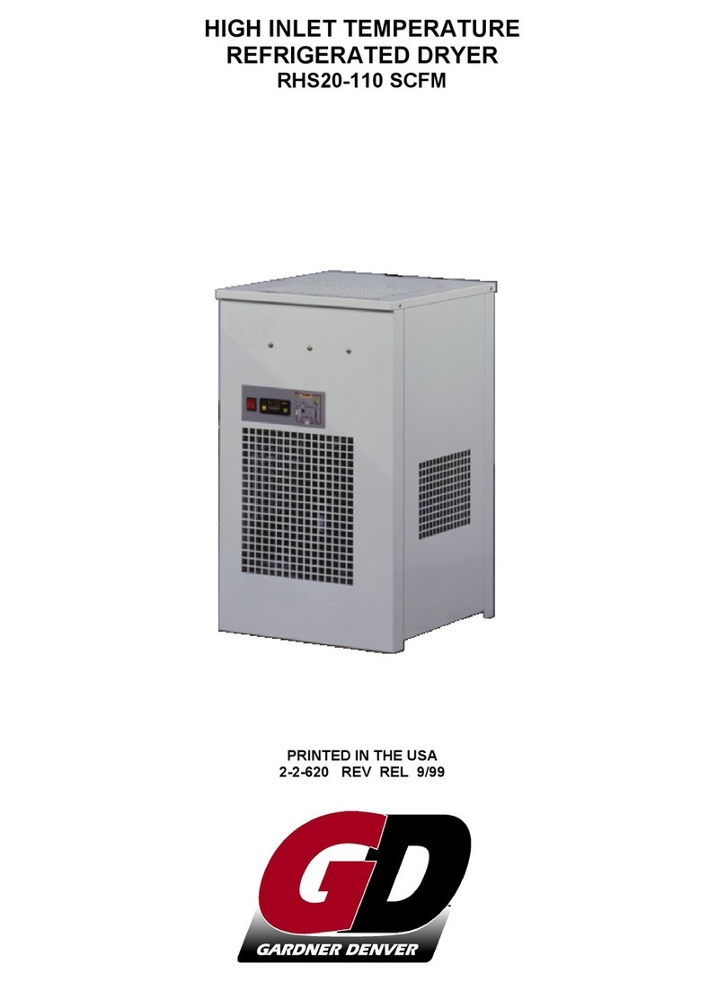
Gardner Denver RHS20 SCFM User manual

Gardner Denver
Gardner Denver 9VXRD Series User manual