Pilz PNOZ Seies User manual

Configuration guide
Technical Catalogue 3.4 – August 2008edition
PNOZmulti Modular Safety System
KURAL TEKNOLOJİELEKTRO MARKET
KURAL TECHNOLOGY ELECTRO MARKET
www.kuralteknoloji.com

Exclusion of liability
We have taken great care in
compiling our application manual. It
contains information about our
company and our products. All
statements are made in accordance
with the current status of technology
and to the best of our know-ledge
and belief. However, we cannot
except liability for the accuracy and
entirety of the information provided,
except in the case of gross
negligence. In particular it should be
noted that statements do not have
the legal quality of assurances or
assured properties. We are grateful
for any feedback on the contents.
August 2008
All rights to this publication are re-
served by Pilz GmbH & Co. KG. We
reserve the right to amend
specifications without prior notice.
Copies may be made for the user’s
internal purposes. The names of
products, goods and technologies
used in this manual are trademarks
of the respective companies.
Why does Pilz offer more?
Because the integrality
of our business activities
is what sets us apart.
Pilz is a solution supplier for all auto-
mation functions. Including standard
control functions. Developments from
Pilz protect man, machine and the
environment. That’s why all our experi-
ence and knowledge goes into
individual products as well as
consistently sophisticated system
solutions.
Sensor technology
Control and communication
Motion Control
Operating and monitoring
Software
Consulting
Engineering
Training
Appropriate services relating to indi-
vidual components and independent
generic services guarantee that our
customers obtain customised
automation solutions, all from one
source.
You can find more details about
Pilz and your products and
services on the Internet:
www.pilz.com
Pilz is a family business
that’s closer to its customers
Pilz has a tradition as a family-run
company stretching back over 50
years. Real proximity to customers is
visible in all areas, instilling
confidence through individual
consultation, flexibility and reliable
service.
We are your contact, guide and
competency leader en route to an
optimum automation solution.
Support –
Technical help round the clock!
Technical support is available from
Pilz round the clock. This service is
provided free of charge beyond
standard business hours.
You can reach our
international hotline on:
+49 711 3409-444

Contents
3
Contents1.02007-11
Basics
1.0
System description
1.1
Installation
1.2
Electrical installation
1.3
Configuration and Wiring
1.4
Products
2.0
Selection guide
2.1
Base units
2.2
Expansion modules
2.3
Adapter for PNOZ ms1p and PNOZ ms2p
2.4
Software
2.5
Applications
3.0
Accessories
4.0
Order reference
5.0
Order reference
5.1
Standards and directives
6.0
Standards and directives
6.1
Service
7.0
Service
7.1

Basics
Pilz GmbH & Co. KG, Sichere Automation, Felix-Wankel-Straße 2, 73760 Ostfildern, Germany
1.0-0
1.0
Basics1.0

Basics
Pilz GmbH & Co. KG, Sichere Automation, Felix-Wankel-Straße 2, 73760 Ostfildern, Germany
2007-11 1.0-1
1.0
Contents Page
System description from 1.1-1
Installation from 1.2-1
Electrical installation from 1.3-1
Configuration and Wiring from 1.4-1

Basics
System description
Pilz GmbH & Co. KG, Sichere Automation, Felix-Wankel-Straße 2, 73760 Ostfildern, Germany
1.1-0
1.1
BasicsSystem description1.1

Basics
Pilz GmbH & Co. KG, Sichere Automation, Felix-Wankel-Straße 2, 73760 Ostfildern, Germany
System description
2007-11 1.1-1
1.1
Contents Page
System description
Overview 1.1-2
Hardware 1.1-3
Software 1.1-4
Maximum system expansion 1.1-5
Diagnostics 1.1-7
Safety 1.1-8

Basics
System description
Overview
2007-11Pilz GmbH & Co. KG, Sichere Automation, Felix-Wankel-Straße 2, 73760 Ostfildern, Germany
1.1-2
1.1
Overview1.12007-11BasicsSystem descriptionOverview
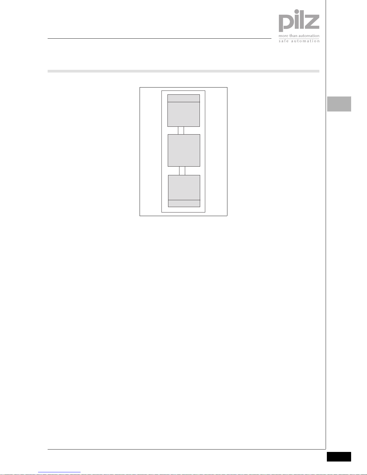
Modular design
`The modular safety system consists
of a base unit and several expan-
sion modules.
`The base unit has several inputs
and outputs and is fully functional
even without an expansion module.
`The expansion modules supple-
ment the base unit with additional
inputs or outputs.
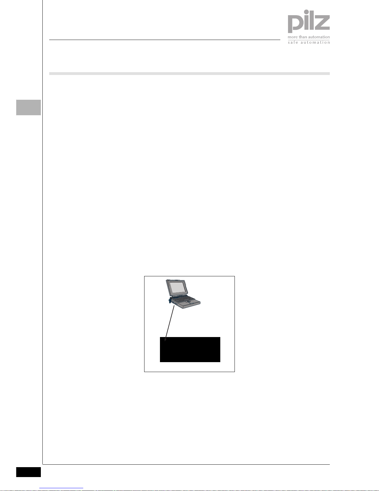
Configuration in the PNOZmulti
Configurator
`The function of the safety system is
established through the PNOZmulti
Configurator.
`The PNOZmulti Configurator is a
graphic tool which is used to define
the functions of the units. Using
predefined symbols, a simple cir-
cuit diagram shows how the units'
inputs and outputs should be con-
nected. This circuit diagram is then
downloaded to the base unit.
`From this data, the base unit recog-
nises the safety functions it is to
perform. For example, safety func-
tions such as E-STOP, two-hand
monitoring and safety gate monitor-
ing are available. With the correct
circuitry it is possible to achieve
categories 2, 3 and 4 in accordance
with EN 954-1.
`The fact that the system is modular
and configurable guarantees the
highest level of flexibility. The safety
system can be expanded or the
safety functions modified at any
time.
Inputs
`Units in the PNOZmulti modular
safety system have semiconductor
inputs for safety-related and stand-
ard applications.
`The inputs for standard applica-
tions can also be set via the serial
interface or via fieldbus modules
(e.g. PROFIBUS-DP, CANopen, ...).
`One expansion module in the
PNOZmulti modular safety system
has safe, analogue inputs. The in-
put signals are converted into digit-
al signals.
`For standard applications, the ex-
act analogue values are made avail-
able to the base unit to forward to a
fieldbus.
Outputs
`Units in the PNOZmulti modular
safety system have both semicon-
ductor and relay safety outputs.
`The outputs for standard functions
use semiconductor technology.
`The safety outputs use semicon-
ductor technology, require no main-
tenance and are non-wearing; they
are therefore suitable for applica-
tions with frequent operations or
cyclical functions. They can be
used for 24 VDC applications.
`The relay safety outputs are suita-
ble for less frequent operations, but
they have a higher breaking capac-
ity and can be used for AC applica-
tions.
`The outputs for standard applica-
tions can also be evaluated via the
serial interface or via fieldbus mod-
ules (e.g. PROFIBUS-DP, CAN-
open, ...).
Base unit + expansion modules
Download
PNOZm Config

Basics
Pilz GmbH & Co. KG, Sichere Automation, Felix-Wankel-Straße 2, 73760 Ostfildern, Germany
System description
Hardware
2007-11 1.1-3
1.1
Hardware1.12007-11BasicsSystem descriptionHardwarePNOZmulti z usammengestellte T exte
Design of the modular safety sys-
tem
The modular safety system consists of
the base unit and expansion modules.
The base unit itself has
`20 inputs
`2 relay outputs
`4 semiconductor outputs
`1 auxiliary output, which is required
for deleting the configuration data
in the base unit
`1 cascading input
`1 cascading output
The number of inputs and outputs can
be increased at any time using the ex-
pansion modules. The modules are
linked via a jumper. The system is con-
figured using the PNOZmulti Configu-
rator. Special expansion modules
enable data to be exchanged via a
fieldbus (non-safety-related) or safe
speed monitoring, for example.
Operation of the units
The PNOZmulti Configurator gener-
ates a project file which is downloaded
to the base unit; there it defines:
`Which safety functions the inputs
are to carry out, e.g. E-STOP moni-
toring, safety gate monitoring
`How the inputs are connected to
the outputs via logic functions
`Which output is configured (semi-
conductor, relay)
The units react the same, irrespective
of these functions:
If the start-up condition of the specific
safety function is met, there will be a
high signal at the output “Out1”. The
output signal can be linked via a logic
function and is then present as the
“Out2” signal at the output on the
PNOZmulti unit.
Fieldbus modules
The fieldbus modules are used to
`Read the diagnostic data
`Set virtual inputs for standard func-
tions
`Read virtual outputs for standard
functions
RS 232 interface
The base unit has an RS 232 interface
to
`Download the project
`Read the diagnostic data
`Set virtual inputs for standard func-
tions
`Read virtual outputs for standard
functions
Safety functions
The safety system has inputs and out-
puts, which can be used for safety
functions. The PNOZmulti safety sys-
tem can be configured to monitor
`E-STOP pushbuttons
`Operating mode selector switches
`Enable switches
`Two-hand buttons
`Safety gates
`Light curtains
`Light beam devices
`Speeds
`Analogue input signals
`Safety mats
`Muting
`Mechanical presses
`Standstill
Various switch types are available for
the required safety-related applica-
tions. With some switch types it is
possible to monitor for simultaneity
(see chapter on “Configuration and
Wiring”).
Standard functions
Expansion modules are available with
inputs and outputs for standard func-
tions.
Press applications
The PNOZ m2p base unit is designed
for applications on mechanical press-
es.
Inputs
Safety
functions
e.g.
E-STOP
safety gate
Outputs
Out1
Logic
functions
e.g.
AND
OR
Delay
Out2
Semiconductor
Relay

Basics
System description
Software
2006-02Pilz GmbH & Co. KG, Sichere Automation, Felix-Wankel-Straße 2, 73760 Ostfildern, Germany
1.1-4
1.1
Software1.12006-02BasicsSystem descriptionSoftware
The functions of the PNOZmulti sys-
tem are defined in the PNOZmulti
Configurator software.
Procedure
`In the PNOZmulti Configurator, the
first step is to enter the units that
are to be used in the safety system.
Each unit must be given a resource
label.
`When all the units are selected, the
interface appears for entering the
circuit diagram. The circuit diagram
describes the application for which
the safety system is to be used. It is
here that you determine which in-
puts are assigned to which safety-
related or standard functions.
`The inputs and/or the results of the
safety-related or standard functions
can be linked through logic func-
tions. The results of the logic func-
tions or the results of the safety-
related or standard functions are
channelled to the outputs on the
PNOZmulti units.
`The circuit diagram is generated on
a graphical interface. Symbols are
provided for the safety-related or
standard functions, logic functions
and the various output types. These
are simply dragged on to a work-
space, configured and intercon-
nected.
`Once the circuit diagram is com-
plete, the data must be saved and
downloaded to the base unit. The
circuit diagram, unit configuration
and all the data that has been en-
tered are stored within a project.
`When the project is saved, various
passwords can be used to protect it
from unauthorised access.
`Once it is saved, the project has to
be downloaded to the base unit. To
do this, the project data is down-
loaded on to a chip card. The data
is either downloaded via the RS 232
interface or via a chip card reader.
`After downloading, a test must be
performed to check that the safety
devices function correctly.

Basics
Pilz GmbH & Co. KG, Sichere Automation, Felix-Wankel-Straße 2, 73760 Ostfildern, Germany
System description
Maximum system expansion
2007-11 1.1-5
1.1
Maximum system expansion1.12007-11BasicsSystem descriptionMaximum system expansion
The PNOZmulti Configurator software
provides support when assembling a
PNOZmulti system. The maximum
system expansion is limited only by
the maximum permitted number of ex-
pansion modules that can be connect-
ed.
The following modules are available:
`Base units
`Expansion modules
`Fieldbus modules
Positioning of units
`Only one base unit may be used.
`Expansion modules and a fieldbus
module may be connected to the
left or right, depending on the base
unit type. The maximum number
per type is given in the tables be-
low.
`The position of the expansion mod-
ules is defined in the PNOZmulti
Configurator.
`Expansion modules for safety-relat-
ed and standard applications may
be combined as required.
`However, if expansion modules of
the same function are combined
into groups it makes things clearer
and simplifies the wiring.
`The power supply for a fieldbus
module is not given a position
number.
`If there is no fieldbus module, the
position numbers to the left of the
base unit will be -1 ... -4.
Base units:
CHIP-Card
PNOZ mo3p
O1+
O0-
O0+
O1-
PROFIBUS-DP
PNOZ mc3p
FAULT
OFF-
LINE
x1
x10
X1
ON-
LINE
ADDRESS
773700
ase unit
Fieldbus module
Max. 8 expansion
modules
8
Position
12...
2
Shield
Power supply
Max. 4 expansion
modules
0-5 -1-2...
Unit type Max. number of expansion modules
installed on the left
Max. number of expansion modules
installed on the right
PNOZ m0p 4 + 1 fieldbus module ---
PNOZ m1p 4 + 1 fieldbus module 8
PNOZ m2p 4 + 1 fieldbus module 8

Basics
System description
Maximum system expansion
2007-11Pilz GmbH & Co. KG, Sichere Automation, Felix-Wankel-Straße 2, 73760 Ostfildern, Germany
1.1-6
1.1
Expansion modules:
Fieldbus modules:
Unit type Function Max. number of expansion
modules
installed on the left
Max. number of expansion
modules
installed on the right
PNOZ ma1p 2 safe analogue inputs 4 ---
PNOZ mc1p 16 outputs for standard func-
tions
--- 8
PNOZ mi1p 8 safe inputs --- 8
PNOZ mi2p 8 inputs for standard functions --- 8
PNOZ ml1p Connection module for 32 virtu-
al inputs and outputs
4 ---
PNOZ mo1p 4 safe 1-pole semiconductor
outputs
--- 6
PNOZ mo2p 2 safe relay outputs --- 6
PNOZ mo3p 2 safe 2-pole semiconductor
outputs
--- 6
PNOZ mo4p 4 safe relay outputs --- 6
PNOZ ms1p 2 incremental encoders or
proximity switches
--- 4
PNOZ ms1p 2 incremental encoders or
proximity switches
--- 4
Unit type Fieldbus Max. number of expansion
modules
installed on the left
Max. number of expansion
modules
installed on the right
PNOZ mc3p PROFIBUS-DP 1 ---
PNOZ mc4p DeviceNet 1 ---
PNOZ mc5p Interbus 1 ---
PNOZ mc5.1p Interbus fibre-optic cable 1 ---
PNOZ mc6p CANopen 1 ---
PNOZ mc7p CC-Link 1 ---
PNOZ mc8p Ethernet IP/Modbus TCP 1 ---
PNOZ mc9p PROFINET IO 1 ---

Basics
Pilz GmbH & Co. KG, Sichere Automation, Felix-Wankel-Straße 2, 73760 Ostfildern, Germany
System description
Diagnostics
2006-02 1.1-7
1.1
Diagnostics1.12006-02BasicsSystem descriptionDiagnostics
The PNOZmulti has many options for
diagnostics and fault detection:
`LEDs on the base unit and expan-
sion modules
`Diagnostic data via serial interface
and fieldbus
`Expanded diagnostic options using
a visualisation system, e.g. PMImi-
cro diag
`Error stack
`Diagnostic word in the PNOZmulti
Configurator
Note
Please refer to the chapters
`“Diagnostic interface” and
`“Diagnostic word”
in the configuration guide “PNOZmulti
– Special applications”.
LEDs on the base unit and expan-
sion modules
The LEDs signal
`Operating statuses (e.g. “RUN”)
`External and internal errors
The key to the LEDs can be found in
the operating instructions supplied
with the units.
Diagnostic Interface
The serial interface on the PNOZmulti
modular safety system is used to
transfer diagnostic data to a user pro-
gram.
Diagnostic data
The diagnostic data can be called up
via the serial interface or via a con-
nected fieldbus.
The diagnostic data may only be used
for non-safety purposes, e.g. visuali-
sation.
Diagnostic data on the PNOZmulti
modular safety system comprises:
`Version:
Product number, unit version, serial
number
`Status of inputs/outputs:
Indicates whether inputs and out-
puts are active or inactive (open/
closed)
`LED status:
Indicates the status of the LEDs on
the base unit and expansion mod-
ules (on/off/flashes), plus the oper-
ating mode (start up, RUN, STOP)
`Simplified status scan:
Shows group messages relating to
the safety system: Signal changes,
LED status, operating statuses
`Virtual inputs and outputs:
Virtual inputs can be set. The status
of the virtual inputs and outputs can
be scanned.
`Diagnostic word:
The diagnostic word contains the
status of elements from the user
program within the PNOZmulti.
`Test data:
To check commmunication.
`Data in table form:
This is structured data (arranged in
tables and segments) from the
PNOZmulti, as it could also be read
via a fieldbus module:
– Configuration
– Status of the inputs and outputs
–LEDstatus
– Diagnostic word
–Elementtypes
Expanded diagnostic options using
a diagnostic terminal, e.g. PMImicro
diag
An expanded diagnsotic configuration
can be created in the PNOZmulti Con-
figurator. The diagnostic configuration
enables appropriate event messages
to be displayed in the case of:
`Errors in or on the PNOZmulti:
Contains the event messages that
are triggered when there are errors
in or on the PNOZmulti (error stack)
`Changes in the operating status of
the PNOZmulti
`which are triggered when safety de-
vices, inputs, outputs and connec-
tion points have a defined status
PNOZmulti event messages can also
be supplemented through additional
information, which is helpful during di-
agnostics.
With expanded diagnostics, a display
unit (e.g. PMImicro diag) is connected
to a PNOZmulti. If an event occurs in
or on the PNOZmulti, an event tele-
gram is sent to the display unit. The
event telegram is evaluated in the dis-
play unit. In most cases, the event
message that corresponds to the
event is displayed and is entered in the
event list. The event message contains
a description of the event. A remedy
can be displayed for each event mes-
sage. The remedy describes how to
react to the event, in other words,
what “actions” to take.
The diagnostic configuration is
project-related, i.e. a separate diag-
nostic configuration is created for
each PNOZmulti project (see Create a
diagnostic configuration).
Then the diagnostic configuration is
downloaded to the PNOZmulti and to
the display unit.
The diagnostic configuration is de-
scribed in detail in the PNOZmulti
Configurator's online help.
Error stack
The error stack on the PNOZmulti con-
tains important information for diag-
nostics and troubleshooting. The error
stack can be read out by the PNOZ-
multi Configurator. It contains mes-
sages and help texts such as
`Hardware errors
`Wiring errors
`Configuration errors
`Errors in the operation of the inter-
face or fieldbus
`Errors in the project's user program
`Messages relating to differences
between the programs stored on
the PNOZmulti and chip card
Diagnostic word
A diagnostic word can be called up for
those elements of the PNOZmulti Con-
figurator interface that have the ability
to store a status:
`Online in the PNOZmulti Configura-
tor
`Via the base unit's serial interface
`Via a connected fieldbus
The diagnostic word contains informa-
tion about a certain element, e.g.:
`Operating statuses (e.g. switch op-
erated)
`Error messages (e.g. monitoring
time elapsed)
An individual bit from a diagnostic
word can be evaluated in the user pro-
gram of the PNOZmulti Configurator.

Basics
System description
Safety
2006-02Pilz GmbH & Co. KG, Sichere Automation, Felix-Wankel-Straße 2, 73760 Ostfildern, Germany
1.1-8
1.1
Safety1.12006-02BasicsSystem descriptionSafetyPNO Zmulti zusammengest ellte Texte
Safety assessments
Before using a unit it is necessary to
perform a safety assessment in ac-
cordance with the Machinery Direc-
tive. The safety system guarantees
functional safety, but not the safety of
the entire application. You should
therefore define the safety require-
ments for the plant as a whole, and
also define how these will be imple-
mented from a technical and organisa-
tional standpoint.
General safety requirements
Always ensure the following safety re-
quirements are met:
`Only install and commission the
unit if you are familiar with the infor-
mation in the operating instructions
or this technical catalogue, as well
as the relevant regulations concern-
ing health and safety at work and
accident prevention.
`Only use the unit for the purpose for
which it is intended and comply
with both the general and specific
technical details.
`Transport, storage and operating
conditions should all conform to EN
60068-2-6, 01/00 (see general
technical details).
`Adequate protection must be pro-
vided for all inductive consumers.
`Do not open the housing or make
any unauthorised modifications.
`Failure to comply with the safety re-
quirements will render the guaran-
tee invalid.
Intended use
`The PNOZmulti Configurator soft-
ware is designed to configure units
from the PNOZmulti modular safety
system for use on E-STOP equip-
ment and safety circuits, in accord-
ance with EN 60204-1 (VDE 0113-
1), 11/98 and IEC 60204-1, 12/97.
`The units' intended use depends on
the individual unit and is therefore
explained in the chapter entitled
“Units”.
`The PNOZ m2p base unit is de-
signed for applications on mechan-
ical presses. Please refer to the
safety guidelines in the chapter on
“Safety solutions for presses” in the
configuration guide “PNOZmulti –
Special applications”.

Basics
Pilz GmbH & Co. KG, Sichere Automation, Felix-Wankel-Straße 2, 73760 Ostfildern, Germany
System description
Safety
2006-02 1.1-9
1.1

Basics
Installation
Pilz GmbH & Co. KG, Sichere Automation, Felix-Wankel-Straße 2, 73760 Ostfildern, Germany
1.2-0
1.2
BasicsInstalla tion1.2

Basics
Pilz GmbH & Co. KG, Sichere Automation, Felix-Wankel-Straße 2, 73760 Ostfildern, Germany
Installation
2007-11 1.2-1
1.2
Contents Page
Installation
Installing within the control cabinet 1.2-2
Installing the units 1.2-3

Basics
Installation
Installing within the control cabinet
2006-02Pilz GmbH & Co. KG, Sichere Automation, Felix-Wankel-Straße 2, 73760 Ostfildern, Germany
1.2-2
1.2
Installing within the control cabinet1.22006-02BasicsInstallationInstalling within the control cabinetPNOZmulti z usammengestellte T exte
`The safety system should be in-
stalled in a control cabinet with a
protection type of at least IP54. Fit
the safety system to a horizontal
DIN rail. The venting slots must face
upward and downward. Other
mounting positions could destroy
the safety system.
`Use the notches on the back of the
unit to attach it to a DIN rail. Con-
nect the safety system to the DIN
rail in an upright position, so that
the earthing springs on the safety
system are pressed on to the DIN
rail.
`The ambient temperature of the
PNOZmulti units in the control cab-
inet must not exceed the figure
stated in the technical details, oth-
erwise air conditioning will be re-
quired.
`To comply with EMC requirements,
the DIN rail must have a low imped-
ance connection to the control cab-
inet housing.
Positioning of units
`Expansion modules and a fieldbus
module may be connected, de-
pending on the base unit type.
`Install the expansion modules in the
position defined in the PNOZmulti
Configurator (see section entitled
“Maximum system expansion” in
Chapter 1.1 “System Description”).

Basics
Pilz GmbH & Co. KG, Sichere Automation, Felix-Wankel-Straße 2, 73760 Ostfildern, Germany
Installation
Installing the units
2006-02 1.2-3
1.2
Installing the units1.22006-02BasicsInstallationInstalling the units Installing a base unit without expan-
sion modules
`The terminator must be fitted to the
side of the base unit marked “Ter-
mination/Link”.
`Do not fit a terminator to the left
side of the base unit.
Connecting the base unit and ex-
pansion modules (PNOZ m1p, PNOZ
m1p coated version, PNOZ m2p on-
ly)
Jumpers are used to connect the
modules.
There are 2 pin connectors on the rear
of the base unit.
`Make sure that no terminator is fit-
ted.
`Connect the base unit, the expan-
sion modules and the fieldbus mod-
ule using the jumpers supplied.
`The terminator must be fitted to the
last expansion module to the right
of the base unit.
`Do not fit a terminator to the last ex-
pansion module to the left of the
base unit.
Terminator Termination/Link
Expansion module 1 ... 8
Jumpers Terminator
Fieldbus module
ase unit
Expansion module 1 ... 4 Power supply

Basics
Electrical installation
Pilz GmbH & Co. KG, Sichere Automation, Felix-Wankel-Straße 2, 73760 Ostfildern, Germany
1.3-0
1.3
BasicsElectrical installation1.3
This manual suits for next models
24
Table of contents
Other Pilz Industrial Electrical manuals
Popular Industrial Electrical manuals by other brands

Tecnoware
Tecnoware FSTEL1K2M user manual

Murata
Murata GRT155C81A105ME01 Series Reference sheet

SCHUNK
SCHUNK PGN-plus-E 80 Assembly and operating manual

Eaton
Eaton DualGuard-S ESF30 Mounting and operating instructions

Murata
Murata GRT21BR61A106KE01 Series Reference sheet

PCB Piezotronics
PCB Piezotronics 352B10 Installation and operating manual