Garz Fricke SANTVEND core User manual

SOLUTIONS THAT COMPLETE!
SANTVEND core
ARM Cortex A9 Single Board Computer
Product Manual
Vending / IOT platform with 3G / 4G modem and MDB interfaces.

Revision Date Author Description
V 1 10.02.2017 CG Initial Release
V 2 12.09.2019 CG Change address
PRODUCT MANUAL
SANTVEND core
Document Revision History
The information in this document is subject to change without prior notice in order to improve reliability, design
and function and does not represent a commitment on the part of the manufacturer.
Online support on www.garz-fricke.com
2

PRODUCT MANUAL
SANTVEND core
Table of Contents
1. Introduction ....................................................................................... 4
2. Safety Hints........................................................................................ 5
3. Product Introduction ......................................................................... 7
3.1 Type Plate and Device Information..........................................................7
3.2 Related Documents and Online Support.................................................8
4. Technical Data.................................................................................... 9
4.1 Block Diagram.........................................................................................10
4.2 Technical Drawing ...................................................................................11
4.3 PCB Design and Pin Assembly................................................................12
5. Installation and Start Up.................................................................... 14
5.1 Connection Scheme.................................................................................14
6. Internal and External Interfaces ....................................................... 15
6.1 Antenna GPS (X1703)...............................................................................15
6.2 Antenna GSM (X1700) ..............................................................................15
6.3 MDB (X1500) ............................................................................................16
6.4 Power (X200)............................................................................................17
6.5 Li - Ion - Akku (X201) ...............................................................................18
Recommendation for an suitable Li-Ion-Accumulator .........18
6.6 RS-232 (X1401) ........................................................................................19
6.7 Speaker (X1301).......................................................................................20
6.8 Microphone (X1300) .................................................................................20
6.9 CAN (X1400) .............................................................................................21
6.10 Ethernet (X1200) ......................................................................................22
6.11 USB - Host (X900) ....................................................................................23
6.12 Push - Buttons (SW600), (SW601), (SW1600), (SW1601).........................23
6.13 JTAG - Debug Interface (X600) ................................................................24
6.14 HDMI (X704) .............................................................................................24
6.15 LVDS 0 (X700) LVDS 1 (X701)....................................................................25
6.16 2nd BL-CTRL (X703) ................................................................................26
6.17 Backlight & PWM (X705) .........................................................................26
6.18 Ambient Light Sensor (X904)...................................................................27
6.19 Touch, 3.3 Vcc (X907)................................................................................27
6.20 Touch, 5.0 Vcc (X902)................................................................................27
6.21 INSIKA (X1800) optional reserved for Internal Use.................................28
Annex A: Hardware Revision Information ......................................................... 29
Annex B: Assembly Options .............................................................................. 30
B-1 WIFI / Bluetooth.......................................................................................30
Annex C: Guidelines and Standards ................................................................. 31
C-1 RoHS Declaration ....................................................................................31
C-2 Supplier Declaration – Directive EG 1907/2006 REACH .........................31
C-3 UL Certification........................................................................................31
C-4 UL Certification........................................................................................31
Annex D: Common Documentation.................................................................... 32
D-1 Warranty hints .........................................................................................32
D-2 Field of Application..................................................................................33
Annex E: Technical Support ............................................................................. 34
General Informations.............................................................35

PRODUCT MANUAL
SANTVEND core
1. Introduction
Thank you very much for purchasing a Garz & Fricke product. Our products are dedicated to professional use
and therefore we suppose extended technical knowledge and practice in working with such products.
The information in this manual is subject to technical changes, particularly as a result of
continuous product upgrades. Thus this manual only reflects the technical status of the
products at the time of printing. Before design-in the device into your or your customer’s
product, please verify that this document and the therein described specification is the latest
revision and matches to the PCB version. We highly recommend contacting our technical sales
team prior to any activity of that kind.
The attached documentation does not entail any guarantee on the part of Garz & Fricke GmbH
with respect to technical processes described in the manual or any product characteristics set
out in the manual. We do not accept any liability for any printing errors or other inaccuracies in
the manual unless it can be proven that we are aware of such errors or inaccuracies or that we
are unaware of these as a result of gross negligence and
Garz & Fricke has failed to eliminate these errors or inaccuracies for this reason.
Garz & Fricke GmbH expressly informs that this manual only contains a general description of
technical processes and instructions which may not be applicable in every individual case. In
cases of doubt, please contact our technical sales team.
In no event, Garz & Fricke is liable for any direct, indirect, special, incidental or consequential
damages arising out of use or resulting from non-compliancy of therein conditions and
precautions, even if advised of the possibility of such damages.
Before using a device covered by this document, please carefully read
Annex „D-1 Warranty hints“
Annex „D-2 Field of Application“
Embedded systems are complex and sensitive electronic products. Please act carefully and
ensure that only qualified personnel will handle and use the device at the stage of development.
In the event of damage to the device caused by failure to observe the hints in this manual
and on the device (especially the safety instructions), Garz & Fricke shall not be required to
honour the warranty even during the warranty period and shall be exempted from the statutory
accident liability obligation. Attempting to repair or modify the product also voids all warranty
claims.
4

PRODUCT MANUAL
SANTVEND core
2. Safety Hints
Please read this section carefully and observe the instructions for your own safety and correct use of the device.
Observe the warnings and instructions on the device and in the manual. Garz & Fricke embedded systems have
been built and tested by us and left the company in a perfectly safe condition.In order to maintain this condition
and ensure safe operation, the user must observe the instructions and warnings contained in this manual.
I. General Handling
Don’t drop or strike the unit: The PCB, display and/or other parts might be damaged.
Keep away from water and other liquids, the unit is not protected against.
Operate the unit under electrical and environmental conditions according to the technical
specification.
The electrical installations in the room must correspond to the requirements of the local
(country-specific) regulations.
Take care that there are no cables, particularly power cables, in areas where persons can trip
over them.
Do not place the device in direct sunlight, near heat sources or in a damp place.
All plugs on the connection cables must be screwed or locked to the housing.
Repairs may only be carried out by qualified specialist personnel authorized by
Garz & Fricke GmbH or their local distributors.
Maintenance or repair on the open device may only be carried out by qualified personnel
authorized by Garz & Fricke GmbH which is aware of with the associated dangers.
II. GSM - Module / SIM Card
It is the responsibility of the user to enforce the country regulation and the specific environment
regulation. Do not insert or remove the SIM when the product is powered.
Every module has to be equipped with a proper antenna with specific characteristics. The
antenna has to be installed with care in order to avoid any interference with other electronic
devices and has to guarantee a minimum distance from the body (20 cm).
It must be assumed that a safe operation is no longer possible, in case
Switch off your wireless device when in hospitals, clinics or other health care facilities. These
requests are designed to prevent possible interference with sentitive medical equipment.
Your cellular terminal or mobile contains a transmitter and receiver. When it is ON , it receives
and transmits radio frequency energy. RF interference can occur if it is used close to TV set,
radio, computer or other electric equipment.
In locations with potencially explosive atmospheres, obey all posted signs to turn off wireless
devices such as your phone or other cellular terminals. Areas with potencially explosive
atmospheres include fuelling areas, below decks on boats, fuel or chemical transfer or storage
facilities, areas where the air contains chemicals or particles such as grain, dust or metal
powders, etc.
5

PRODUCT MANUAL
SANTVEND core
III. Electricity
The embedded systems may only be opened in accordance with the description in this user’s
manual for
- replacing of the (rechargeable, where applicable) lithium battery and/or
- configuration of interfaces, where applicable
These procedures have to be carried-out only by qualified specialist personnel.
When accessing internal components the device must be switched off and disconnected from
the power source.
When purchased core or basic versions without protecting back cover, don’t touch the PCB
directly with your fingers. Especially these products need to be handled very carefully.
Don’t operate or handle the unit without typical ESD protection measures, such as ground
earthing.
Operate the unit according to the technical specification only.
IV. Damage or Permanent Malfunction
It must be assumed that a safe operation is no longer possible, in case
-the device has visible damage or
-the display is dark or shows strange pattern for longer period
-the device doesn’t react after a reset
In these cases the device must be shut down and secured against further use
6
PRODUCT MANUAL
SANTVEND core
3. Product Introduction
This document is applicable for hardware revisions 1.0 or later of the SANTVEND series.
Please find the hardware version grid in „Annex A: Hardware Revision Information“:
SANTVEND is an Embedded System to be used as human machine interface (HMI) in various applications.
Please refer to Annex „D-2 Field of Application“ for further information. The system is equipped with a large
number of industrial interfaces. A wide variety of options is available as well.
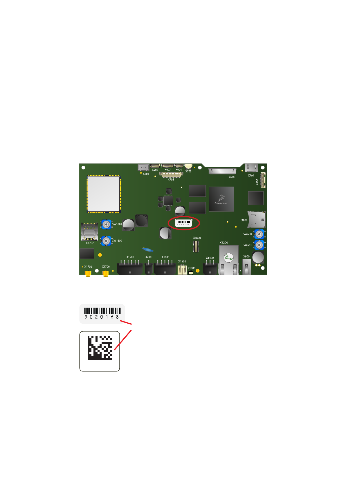
3.1 Type Plate and Device Information
For service and later identification of the device, the type plate contains important information.
code defines the serial number
7
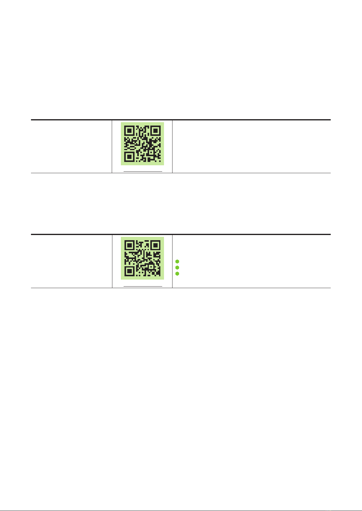
Flash-N-Go
http://mx31.de/1h
Contains information about the usage of the G&F Flash-N-Go solution
which consists of three submodules:
Flash-N-Go Boot (A tiny boot loader)
Flash-N-Go System (A maintenance os)
Flash-N-Go Update (A GUI based update solution for all os)
Linux Yocto Jethro
http://mx31.de/1g
Contains information about Linux BSP with development environment
Linux Embedded System Yocto (Codename: Jethro, Version 3.0) includes
first information about the bootloader Flash-N-Go
PRODUCT MANUAL
SANTVEND core
3.2 Related Documents and Online Support
This document contains SBC specific information. The following additional documentations are available:
OPERATING SYSTEMS
UPDATE
8

CPU x2
CPU Type i.MX6Dual
Core Class ARM Cortex - A9
Core Clock 1 GHz
Features
NEON for SIMD media acceleration and VFP operations; Multi-format HD 1080p video decoder and HD
720p video encoder hardware engine; L1 cache, 32 KB for instruction, 32 KB for data; 1 MB L2 cache
512 KB L2 cache
HW Accelerators Open VG 1.1
RTC Accuracy: +/- 30 ppm at 25°C
Super Cap Buffer for 24h
Memory
eMMC Flash 4 GB MLC eMMC
RAM Standard 2 GB 32 bit DDR3L
Micro SD Card Slot 4 bit MMC/SDIO/SD/SDHC
Operating Systems
Supported OS
Linux Yocto
Communication Interfaces
Network
1x 10/100 Mbit/s Ethernet (RJ-45)
USB 2.0 1x 480 Mbit/s Type A (Host)
CAN Fieldbus 1x CAN (ISO/DIS 11898)
MDB 1x Master, 1x Slave
Modem 3G / 4G, GPS (optional); Micro Sim Socket
RS-232 1x RS-232 (RX/TX/CTS/RTS) and 1x RX, TX
Synchronous Serial Interfaces SPI up to 2 chip selects; Pinning for RFID-I / F (Karl³)
BLE Modul (Option) Single Mode BLE V 4.0 Slave
INSIKA (Option) Socket for optional Smart-Card Interface (Plug In)
Misc. 2x Service Button
Video
Video output HDMI 1.4 Type C Connector; + On / Off, PWM 2nd Backlight control con.
Audio
Speaker output 1x speaker (connector), 1.5 W RMS (8)
Micro IN 1x microphone connector
Display and Touch
Display Interface
Dual Channel 24bpp LVDS
Sensor Ambient-Light-Sensor (external via I²C)
Touch Interface PCAP I²C
Backlight Interface
+12 V, +5V, on/off, PWM
Device Dimensions
W x H x D 160 x 18 x 95 mm; PCB 160 x 95 mm
Weight 115 g
Power Supply
Supply Voltage
Nom. 24 V DC / max. 10 to 42 V DC
Consumption Typ. 3.0 W; max. tbd.
Li-Ion-Akku 3.7 V / 2.0 to 4.0 Ah for Modem and Backup-Power
Charge Controller Internal
Typical Environmental Conditions
Storage Temp. -20 to +70 °C without Li-Ion-Akku
Operating Temp. 0 to +40 °C (normal operation) -20 to +60 °C without charge Li-Ion-Akku
Humidity 5 to 90 % RH
Max. Operating Altitude ty 3.000 m
Max. Storage/Transit Altitude 10.000 m
Noise Level [db(A)] @ 1m <<40 (fanless design)
Lifetime
MTBF ≥ 50.000 h
PRODUCT MANUAL
SANTVEND core
4. Technical Data
9

PRODUCT MANUAL
SANTVEND core
4.1 Block Diagram
10
1x Speaker
2-pole JST Audio
Amplifier
Block Diagram SANTVEND
i.MX6
Backlight
12-pole Molex
USB-Host
USBA
I²C-3
DRAM DDR3L
Audio
Codec
FlexCAN-1
AUD3
SPI-1
eMMC
24 V DC
2-pole Modex Step Down
Converter
PMIC Power
Ambient-Light
5-pole JST
SD-Card
Connector
CAN
6-pole Molex
LVDS0
LVDS1
2x Display LVDS
20-pole Hirose
GPIO
PWM1_OUT
HDMI
HDMI
Type C
2x RS-232
10-pole Molex
RS-232
Transceiver UART-2,3
UART-4,5
Cap.Touch
6-pole JST
BLE-Modul
RJ-45
Jack
Ethernet
Phy
MDIO/RMII
UART-3
IC-1
GPIO
USDHC2
SPI-3
USDHC4
RTC
Super-
Cap
IC-1
CAN
Transc.
8-pole JST
USB OTG
Cap.Touch
7-pole JST
Charger
Akku
3-pole
JST
MDB (M/S)
12-pole Molex
MDBTran-
sceiver
Micro
2-pole JST
RFID-I / F
(Karl³)
Antenne
MMCX
Modem
3G-4G
UART 1
USB H1
GPIO
PWM2_OUT
BL-Control
GPS MMCX
Socket
INSIKA

PRODUCT MANUAL
SANTVEND core
4.2 Technical Drawing
6x
2,7
160
156,5
102,9
3,5
15
101
3,5
91,5
95
5,8
19
15,5
3,5
SANTVEND core
Missing dimensions according to 3D CAD files
11

Pos. Description
1GPS (X1703)
2GSM (X1700)
3MDB (X1500)
4Power (X200)
5 RS-232 (X1401)
6Speaker (X1301)
7Microphone (X1300)
8CAN (X1400)
9Ethernet (X1200)
10 USB - Host (X900)
11 Boot Select (SW600)
12 Reset (SW601)
13 Service 1 (SW1600)
Pos. Description
14 Service 2 (SW1601)
15 Micro SD card reader (X800)
16 JTAG - Debug Interface (X600)
17 HDMI (X704)
18 LVDS 1 (X700)
19 INSIKA (X1800)
20 2nd BL-CTRL (X703)
21 Backlight & PWM (X705)
22 Ambient Light Sensor (X904)
23 Touch, 3.3 Vcc (X907)
24 Touch, 5.0 Vcc (X902)
25 Li - Ion - Akku (X201)
26 Micro SIM - Card (X1702)
PRODUCT MANUAL
SANTVEND core
4.3 PCB Design and Pin Assembly
As this manual describes a core version, the internal and external interfaces will be mentioned in the following
chapter.
(Exemplary Illustration front side. The illustration shows the fully equipped SANTVEND Quadcore light. It shows
no heatsink to provide a better overview.)
12

Pos. Description
27 LVDS 2 (X701)
28 Ambient - Light - Sensor (X905)
29 SPI (X1600)
PRODUCT MANUAL
SANTVEND core
(Exemplary Illustration back side)
13
X701
X905 X1600
Pos.
Description
1
DC in
2
RS-232
3
Ethernet
4
USB-Host
Exemplary Illustration
PRODUCT MANUAL
SANTVEND core
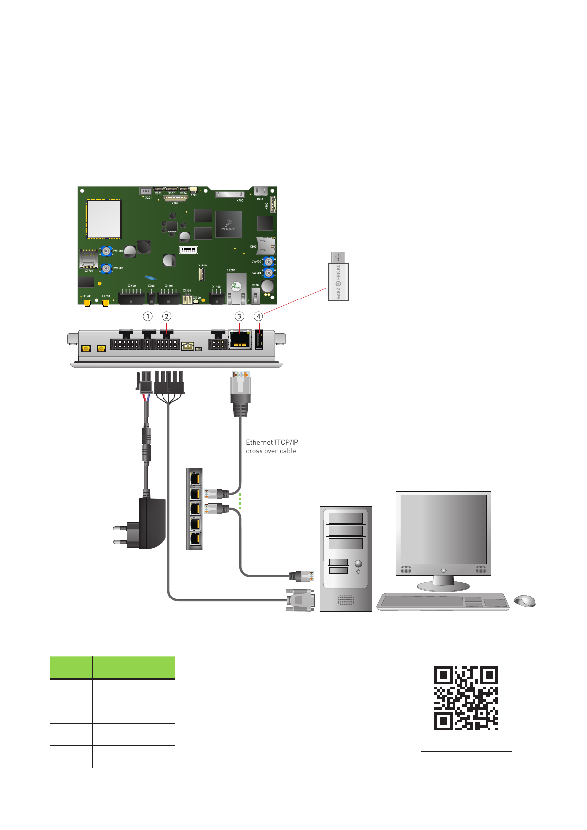
5. Installation and Start Up
The content of this document is limited to explain the device connectors and how to access SANTVEND via FTP
over your local area network (LAN) within a few seconds. For advanced hardware specifications and software
support, please refer to chapter „3.2 Related Documents and Online Support“
http://mx31.de/1f
5.1 Connection Scheme
14
Ethernet (TCP/IP) via
cross over cable or switch
USB Accessory
Memory stick,
mouse
RS-232 (Serial)
Debug-PC /
Periphery
2x RS232 Speaker??? ?????? CAN/RS485 Digital I/O
Power LAN
USB-Host
Pin Name Description Level
Center RF-IN 50 Ohm; Feeding active GPS antenna +3,3V
Shield GND
Header: MMCX_SMD_EdgeMount 090°
Pin Name Description Level
Center RF-I/O 50 Ohm; GSM antenna
Shield GND
Header: MMCX_SMD_EdgeMount 090°
PRODUCT MANUAL
SANTVEND core
6. Internal and External Interfaces
6.1 Antenna GPS (X1703)
6.2 Antenna GSM (X1700)
Application Notes
The usage of a Quad Band Antenna (850/900/1800/1900), VSWR: ≤ 2.0 is recommended
For cabled aerials, the cable length should not exceed 3 m (dedicated cable type RG174)
For larger cable length not exceeding 30 m, the usage of a special low loss cable is essential.
Additional cable adapters are needed to contact the low loss cable properly.
Outdoor aerials have to be designed and grounded according to DIN EN 60728-11
The grounding of the antenna is not obliged, when the antenna is installed
more than 2 m below the roof edge and
less than 1.5 m away from the building
For installation in countries outside Germany, please ensure to act in accordance with the local
restrictions and regulations!
15

Pin Name Description Level
1VCC_MDB-S Eingang VCC (complete system) 12-24 VDC
2GND Common GND GND
3WakeUp-MDB-S WakeUp-IO (In/Open Collector) 5V
4TX-MDB-S OUT TX MDB Slave 5V
5RX-MDB-S IN RX MDB Slave 5V
6GND Common GND GND
7VCC_MDB-M Ausgang VCC MDB Master 12-24 VDC
8GND Common GND GND
9WakeUp-MDB-M WakeUp-IO (In/Open Collector) 5V
10 RX-MDB-M IN RX MDB Master 5V
11 TX-MDB-M OUT TX MDB Master 5V
12 GND Common GND GND
Header: Type 43045-1200 / 12 pol. Molex MicroFit 090°
Plug: 43025-1200 12 pol. Molex MicroFit
crimp contact Molex 43030-0007
PRODUCT MANUAL
SANTVEND core
6.3 MDB (X1500)
16
1
7
Pin Name Description Level
1GND Common GND GND
2Power In Eingang VCC (complete system) Nom. 12 to 24 V DC
Header: Molex 43045-0200 Micro-Fit 2p
Plug: Molex 43025-0200 Micro-Fit 2p,
crimp contact Molex 43030-0007
PRODUCT MANUAL
SANTVEND core
6.4 Power (X200)
Caution:
Power supplies connected to this device must be compliant to the requirements of
“limited power sources” (LPS) to prevent the end-user from danger in case of a fault.
17
1

PRODUCT MANUAL
SANTVEND core
Electrical characteristics
Nominal voltage 3,7 V
Nominal capacity (minimum requirement) 2 Ah
Initial Internal Impedance Less than 100m
NTC 10KOhm 10% @25°C
Operating conditions
Operating Temperature Charge : 0 .. +40 °C
Discharge : -20 .. +60 °C
Charge System Constant current: 0,2 .. 1,0 C
Constant voltage: 4,2 V
Maximum continuous discharge current 1,0 .. 2,0 C
Pulse discharge current 2,0 .. 4.0 C
Safety Requirements
Protection Circuit See schematic, wiring diagram
Over Voltage Cut OFF 4.3 V
Under Voltage Cut OFF 2.25 V
Overload Cut OFF (Short circuit protection) Reversible fuse
NTC Built in (10K)
Approval & Conformity UL, CE
Pin Name Description Level
1GND Common GND GND
2NTC 10K NTC 3.3 V
3V Li Ion Akku Plus Li-Ion-Akku 4.2 V
Header: Type: B3B-XH-A / 3pol. JST-XH, THT 180°
Plug: XHP-3 / 3pol. JST-XH
crimp contact SXH-001T-P0.6 (22-28 AWG Tin)
3RO\IXVH 17&
3OXV
7HPSB6HQVH
0LQXV*1'
3URWHFWLRQ&LUXLW
3
;+3
/LWKLXP,RQ%DWWHU\3DFN
6.5 Li - Ion - Akku (X201)
Recommendation for an suitable Li-Ion-Accumulator
Schematic, wiring diagramm
18

Pin Name Description Level
1GND Common GND GND
2RS232-1_TX RS232-1_TX V.28
3RS232-1_RX RS232-1_RX V.28
4RS232-1_RTS RS232-1_RTS V.28
5RS232-1_CTS RS232-1_CTS V.28
6GND Common GND GND
7RS232-2_TX RS232-2_TX V.28
8RS232-2_RX RS232-2_RX V.28
9MISC_WU WakeUp-IO (In/Open Collector) 5 V
10 GND Common GND GND
Header: Type 43045-1000 / 10pol. Molex MicroFit 090°
Plug: 43025-1000 / 10 pol. Molex MicroFit
crimp contact Molex 43030-0007
PRODUCT MANUAL
SANTVEND core
6.6 RS-232 (X1401)
Note: Not available if INSIKA-Interface populated.
19
1
6

Pin Name Description Level
1GND Common GND GND
2MIC_IN MIC & MIC_BIAS 3.3 V
Header: Type SM02B-SURS-TF / 2pol. RM 0.8mm; JST SUR-Serie 090°
Plug: Type 02SUR-32S / 2pol. RM 0.8mm; JST SUR-Serie
(2 Position Rectangular Receptacle Connector IDC Tin 32 AWG)
Pin Name Description Level
1Speaker+ OUT D-Class-Amp. 5 V
2Speaker- OUT D-Class-Amp. 5 V
Header: Type S2B-PH-SM3-TB / 2pol. RM2.0mm; JST PH-Serie 090°
Plug: Type PHR-2 / 2pol. RM2.0mm; JST PH-Serie
crimp contact JST SPH-002T-P0.5L
PRODUCT MANUAL
SANTVEND core
6.7 Speaker (X1301)
6.8 Microphone (X1300)
20
1
1
Table of contents


