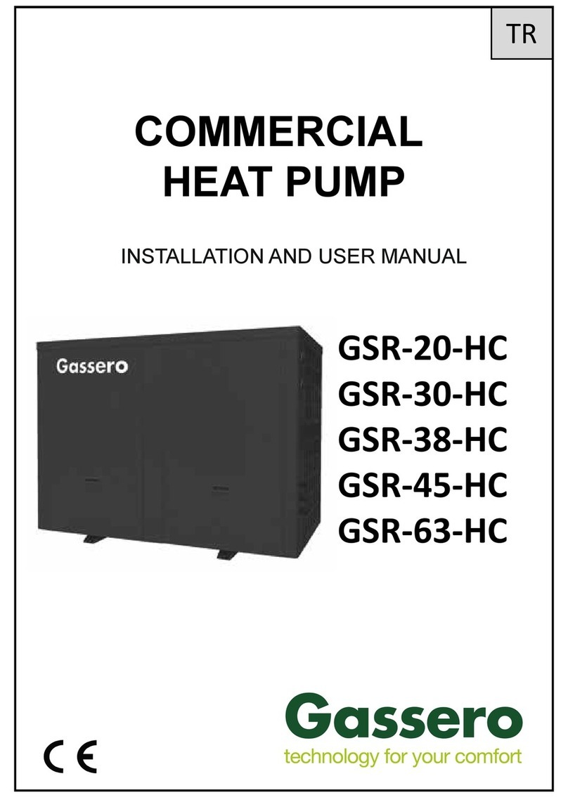
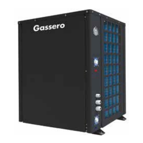
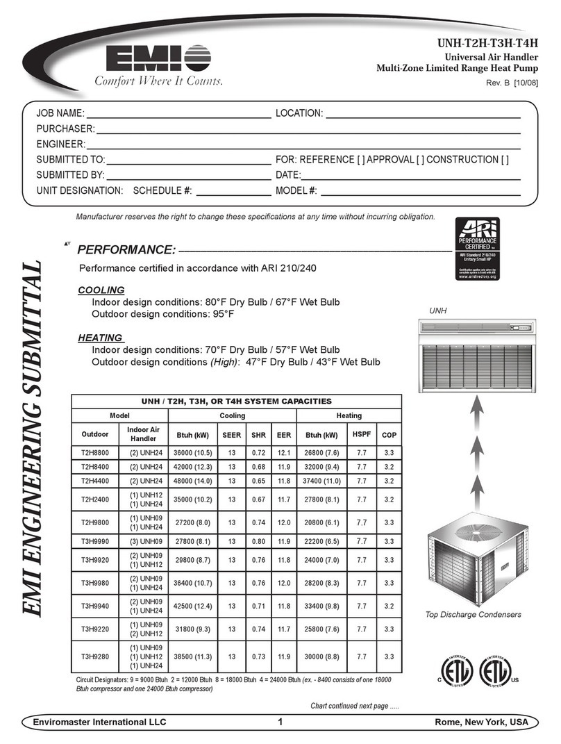
gassero GSR-M4-DC/M User manual

INSTALLATION AND USER MANUAL
EN
50
70
90
115
125
150
MONOBLOCK -DC INVERTER
HEAT PUMP
GSR-M4-DC/M
GSR-M6-DC/M
GSR-M8-DC/M
GSR-M10-DC/M
GSR-M12-DC/M
GSR-M14-DC/M
GSR-M16-DC/M
GSR-M10-DC/T
GSR-M12-DC/T
GSR-M14-DC/T
GSR-M16-DC/T

Content
1
ATTENTION !
Before installing/mounting the heat pump please read this user
manual carefully!
Otherwise heat pump may be damaged, which may result in serious
injury or even death for service personel and user.
Heat pump shall be installed and start up by qualified personel
approved by GASSERO.
1Meanıngs of the symbols and safety 212 2-Way Valve 24
1.1 Meanıngs of the symbols 213 3-Way Valve 24
2General 214 Other Thermal 25
3Diagram of the Operating Principle 10 15 Optional Electric Heater 27
4Operating Principle of the Unit 11 16 Gate-controller 27
5Nomenclature 12 17 Charging and Discharging of Refrigerant 28
6Installation Example 13 18 Installation of Insulated Water Tank 30
7Main Components 14 18.1 Installation measure 30
8Installation Guideline of Monobloc Unit 15 18.2 Connection of waterway system 31
8.1 Instruction to installation 15 18.3 Requirements on water quality 32
8.2 Installation of monobloc unit 15 19 Electric wiring work 33
8.2.1
Selection of installation location
of monobloc unit
15 19.1 Wiring principle 33
8.2.2 Outline dimension of monobloc unit 16 19.2
Specification of power supply wire and
leakage switch
33
8.2.3 Space requirements for installation 17 20 Control Board 34
8.2.4 Precautions on installation of monobloc unit 17 21 Electric Wiring 43
8.2.5 Water pipe connection of monobloc unit 17 22 Terminal Board 44
8.2.6 Usage of rubber rings 18 23 Commissioning 48
8.2.7 Usage of reserved communication cable 18 23.1 Check before startup 48
8.3 Safety operation of flammable refrigerant 19 23.2 Test run 49
9Installation of Hydraulic Unit 20 24 Daily Operation and Maintenance 50
9.1 Available External Static Pressure of Outlet 20 24.1 Troubleshooting 50
9.2 Water volume and expansion vessel pressure 20 24.2 Recovery 51
9.3
The method of calculating the charging pressure of
expansion vessel
21 24.3 Decommissioning 52
9.4 Selection of expansion vessel 22 24.4 Notice before Seasonal Use 52
10 Remote Air Temperature Sensor 22 24.5 Precautions for Freeze Protection in Winter 52
11 Thermostat 23

2
The symbols which are used in this document and their meanings are as follows:
This sign indicates that the items must be observed. Improper operation may
cause damage to people or property.
WARNING:
If not abide strictly, it may cause severe damage to the unit or the
people.
This sign indicates that the operation must be prohibited. Improper operation may
cause severe damage or death to people
NOTE:
If not abide strictly, it may cause slight or medium damage to the unit or the people.
NOT:
-After receipt of the unit, check it for appearance, unit model compared with your desire and
attachments.
-Design and installation work of the unit must be performed by authorized personnel according
to applicable laws and regulations and this Instruction.
-After installation work, the unit cannot be energized unless there is not any problem in check.
-Ensure periodical clean and maintenance of the unit after normal operation of the unit for
longer life and reliable operation.
-If thesupply cord is damaged, it must be replaced by the manufacturer, its service agent or
similarly qualified persons in order to avoid ahazard.
-The appliance shall be installed in accordance with national wiring regulations.
-This product is akind of comfort air conditioning, and is not allowed to be installed where
there are corrosive, explosive and inflammable substances or smog;otherwise it would lead
to operation failure, shortened service life, five hazard or even severe injuries.Special air
conditions are required for where mentioned above.
2. General
These installation and maintenance instructions are prepared for the Dc Inverter Heat Pumps specified
below:
GSR-M4-DC/M GSR-M10-DC/T
GSR-M6-DC/M GSR-M12-DC/T
GSR-M8-DC/M GSR-M14-DC/T
GSR-M10-DC/M GSR-M16-DC/T
GSR-M12-DC/M
GSR-M14-DC/M
GSR-M16-DC/M
CE LABEL:
This heat pump complies with the essential requirements of the relevant European directives. The CE
marking certifies that the products meet the essential requirements of the applicable regulations in
accordance with the type of label. Manufacturer can be consulted for the declaration of conformity.
1.1 Meanıngs of the symbols
1. Meanıngs of the symbols and safety

3
Correct Disposure:
This marking indicates that this product should not be disposed with other household wastes
throughout the EU.To prevent possible harm to the environment or human health from
uncontrolled waste disposal,recycle it responsibly to promote the sustainable reuse of material
resources. To retuern your used device,please use the return and collection systems or contact
the retailer where the product was purchased. They can take this product for environmental safe
recycling.
WARRANTY PERIOD AND LIFE TIME:
Warranty is 2 years from the date of invoice, unless other terms are agreed separately.
Service life of the heat pump is 10 years (this period can be change according to the installation, water
quality and other environmental conditions).
CONSUMER RIGHTS:
Consumers can apply for complaints and appeals to consumer courts and consumer arbitration
committees.
In case of defective goods;
a) Withdraw from the contract by stating that it is ready to return the product;
b)If all costs incurred do not incur excessive costs, to request free repair of the product,
c) Requesting the replacement of the product with anon-defective product,
One of the rights can be used.

WARNING
Be sure to pull out the power plug
and drain the indoor unit and water
tank when unit is not in use for a
long time.
Otherwise, the accumulated dust
may cause overheating,fire or
freeze of water tank or coaxial
heater exchanger in winter.
4
Once abnormality
likeburning smell occurs,
please cut off the power
supply immediately and
then contact with service
center.
Don't operate the unit with
wet hand.
Otherwise, it may cause
electric shock.
Before installation,please see if
the voltage of local place
accords with that on nameplate
of unit and capacity of power
supply, power cord or socket is
suitable for input power of this
unit.
Special circuit must be
adopted for power supply to
prevent fire.
Do not use octopus
multipurpose plug or mobile
terminal board for wire
connection.
Never damage the electric wire
or use the one which is not
specified.
Otherwise, it may cause
overheating or fire.
Before cleaning please cut off the
power supply.
Otherwise, it may cause electric
shock or damage.
The power supply must adopt
special circuit with leakage switch
and enough capacity.
User can not change power cord
socket without prior consent.
Wiring working must be done by
professionals. Ensure good
earthing and don't change
earthing mode of unit.
Earthing: the unit must be
earthed reliably ! The earthing
wire should
connect with special device of
buildings.
Never insert any foreign
matter into outdoor unit to
avoid damage .And never
insert your hands into the air
outlet of outdoor unit.
Don't attempt to repair
the unit by yourself.
Improper repair may cause
electric shock or fire, so you
should contact the service center
to repair.
Don't step on the top of the
unit or place anything on it.
There is the danger of fall of
things or people.

5
WARNING !
Never block the air inlet and
outlet of unit.
It may reduce efficiency or cause
stop of the unit and even fire.
Keep pressurized spray, gas
holder and so on away from the
unit above 1m .
It may cause fire or
explosion.
Please note whether the
installation stand is firm enough
or not.
If damaged, it may cause fall of
the unit and injury of people.
Unit should be installed
at the place with good ventilation
to save energy.
When there is not water in water
tank, never power the unit on to
run.
WARNING :
Do not use means to accelerate the defrosting process or to clean, other than those recommended
by the manufacturer.Should repair be necessary, contact your nearest authorized service centre.Any
repairs carried out by unqualified personnel may be dangerous.The appliance shall be stored in a
room without continuous operating ignition sources.(for example:open flames, an operating gas
appliance or an operating electric heater.) Do not pierce or burn.
Appliance shall be installed, operated and stored in aroom with afloor area larger than Xm
.(Please refer to table “a” in section of “Safety Operation of Inflammable Refrigerant” for space X.)
Appliance filled with flammable gas R32.For repairs, strictly follow manufacturer’s instructions only.
Be aware that refrigrants not contain odour.Read specialist’s manual.
If astationary appliance is not fitted with asupply cord and aplug, or with other means for
disconnection from the supply mains having acontact separation in all poles that provides full
disconnection under overvoltage category III conditions, the instructions shall state that means for
disconnection must be incorporated in the fixed wiring in accordance with the wiring rules.
This appliance can be used by children aged from 8years and above and persons with reduced
physical, sensory or mental capabilities or lack of experience and knowledge if they have been given
supervision or instruction concerning use of the appliance in asafe way and understand the hazards
involved.Children shall not play with the appliance.Cleaning and user maintenance shall not be made
by children without supervision.
The appliance shall be stored in awell-ventilated area where the room size corresponds to the
room area as specified for operation.
The appliance shall be stored in aroom without continuously operating open flames (for example
an operating gas appliance) and ignition sources (for example an operating electric heater).
The appliance shall be stored so as to prevent mechanical damage from occurring.

6
NOTE:
Appliance filled with flammable gas R32.
Before use the appliance, read the owner’s manual first.
To realize the function of the air conditioner unit, aspecial refrigerant circulates in the system.
The used refrigerant is the fluoride R32,which is specially cleaned.The refrigerant is flammable
and inodorous.Furthermore, it can leads to explosion under certain conditions.But the
flammability of the refrigerant is very low.It can be ignited only by fire.
Compared to common refrigerants, R32 is anonpolluting refrigerant with no harm to the
ozonosphere.The influence upon the greenhouse effect is also lower. R32 has got very good
thermodynamic features which lead to areally high energy efficiency.The units therefore need a
less filling.
Before installation, please check if the adopted power is accordance with that listed on
nameplate, and check the safety of power.
The unit shall contact with the supply mains by afull disconnection device under overvoltage
category Ⅲ.
Before using, please check and confirm if wires and water pipes are connected
correctly to avoid water leakage, electric shock or fire etc.
Don’t operate the unit with wet hand, and don’t allow children to operate the unit.
The On/off in the instruction is for the operation to on and off button of PCB for users;
cut off power means to stop supplying power to the unit.
Don’t directly expose the unit under the corrosive ambient with water or dampness.
Don’t operate the unit without water in water tank .The air outlet/inlet of unit cannot be
blocked by other objects.
The water in unit and pipeline should be discharged if the unit is not in use, to prevent the
water tank, pipe line and water pump from frost-cracking.
Never press the button with sharp objects to protect manual controller.Never use other wires
instead of special communication line of the unit to protect control elements.Never clean the
manual controller with benzene, thinner or chemical cloth to avoid fading of surface and failure
of elements.Clean the unit with the cloth soaked in neutral eradicator.Slightly clean the display
screen and connecting parts to avoid fading.
The power cord must be separated with the communication line.
Any person who is involved with working on or breaking into arefrigerant circuit should hold a
current valid certificate from an industry-accredited assessment authority, which authorises their
competence to handle refrigerants safely in accordance with an industry recognised assessment
specification.
Servicing shall only be performed as recommended by the equipment manufacturer.
Maintenance and repair requiring the assistance of other skilled personnel shall be carried out
under the supervision of the person competent in the use of flammable refrigerants.

7
Maximum and minimum water operating temperatures
Item Minimum water operating
temperatures
Maximum
water operating
temperatures
Cooling 7°C 25°C
Heating 25°C 60°C
Water heating 40°C 80°C
Maximum and minimum water operating pressures
Item Minimum water operating
pressures
Maximum water
operating pressures
Cooling
0.05MPa 0.25MPa
Heating
Water heating
maximum and minimum entering water pressures.
Item Minimum entering water
pressures
Maximum entering
water pressures
Cooling
0.05MPa 0.25MPa
Heating
Water heating
The range of external static pressures at which the appliance was tested (add-on
heat pumps, and appliances with supplementary heaters, only);If the supply cord
is damaged, it must be replaced by the manufacturer, its service agent or similarly
qualified persons in order to avoid ahazard.
The appliance is intended to be permanently connected to the water mains and not
connected by ahose-set.
If there is any question, please contact with local dealer, authorized service center,
agencies or our company directly.

8
NOTE
If any hot work is to be conducted on the refrigeration equipment or any associated
parts,appropriate fire extinguishing equipment shall be available to hand.Have adry
powder or CO2fire extinguisher adjacent to the charging area.
Where electrical components are being changed, they shall be fit for the purpose
and to the correct specification.At all times the manufacturer’s maintenance and
service guidelines shall be followed.If in doubt consult the manufacturer’s technical
department for assistance.
The following checks shall be applied to installations using flammable refrigerants:
–the charge size is in accordance with the room size within which the refrigerant
containing parts are installed;
–the ventilation machinery and outlets are operating adequately and are not
obstructed;
–if an indirect refrigerating circuit is being used, the secondary circuit shall be
checked for the presence of refrigerant;
–marking to the equipment continues to be visible and legible. Markings and signs
that are illegible shall be corrected;
–refrigeration pipe or components are installed in aposition where they are
unlikely to be exposed to any substance which may corrode refrigerant containing
components, unless the components are constructed of materials which are inherently
resistant to being corroded or are suitably protected against being so corroded.
Repair and maintenance to electrical components shall include initial safety checks
and component inspection procedures.If afault exists that could compromise safety,
then no electrical supply shall be connected to the circuit until it is satisfactorily dealt
with.If the fault cannot be corrected immediately but it is necessary to continue
operation, an adequate temporary solution shall be used.This shall be reported to the
owner of the equipment so all parties are advised.
Initial safety checks shall include:that capacitors are discharged:this shall be done
in asafe manner to avoid possibility of sparking;that no live electrical components
and wiring are exposed whiule charging, recovering or purging the system; that there
is continuity of earth bonding.

9
During repairs to sealed components, all electrical supplies shall be
disconnected
from the equipment being worked upon prior to any removal of sealed covers, etc.
If
it is absolutely necessary to have an electrical supply to equipment during
servicing,
then apermanently operating form of leak detection shall be located at the
most
critical point to warn of apotentially hazardous situation.
Particular attention shall be paid to the following to ensure that by working
on
electrical components, the casing is not altered in such away that the level
of
protection is affected.This shall include damage to cables, excessive number
of
connections, terminals not made to original specification, damage to seals,
incorrect
fitting of glands, etc.
Ensure that apparatus is mounted securely.
Ensure that seals or sealing materials have not degraded such that they no longer
serve the purpose of preventing the ingress of flammable atmospheres.Replacement
parts shall be in accordance with the manufacturer’s specifications.
NOTE The use of silicon sealant may inhibit the effectiveness of some types of leak
detection equipment.
Intrinsically safe components do not have to be isolated prior to working on them.
Do not apply any permanent inductive or capacitance loads to the circuit
without
ensuring that this will not exceed the permissible voltage and current permitted for
the
equipment in use.
Intrinsically safe components are the only types that can be worked on while live in
the presence of aflammable atmosphere.The test apparatus shall be at the
correct
rating.
Replace components only with parts specified by the manufacturer.Other
parts
may result in the ignition of refrigerant in the atmosphere from aleak.
Check that cabling will not be subject to wear, corrosion, excessive
pressure,
vibration, sharp edges or any other adverse environmental effects.The check
shall
also take into account the effects of ageing or continual vibration from sources
such
as compressors or fans.
Under no circumstances shall potential sources of ignition be used in the searching
for or detection of refrigerant leaks. A halide torch (or any other detector using anaked
flame) shall not be used.
Equipment shall be labelled stating that it has been de-commissioned and emptied
of refrigerant.The label shall be dated and signed.Ensure that there are labels on the
equipment stating the equipment contains flammable refrigerant

10
3. Diagram of the Operating Principle
Flow
switch
Expansion
Vessel Automatic
exhaus t valve
Note: the swimming pool, solar kit and water mixing accessory are optional parts. When they are required,
please contact the manufacturer.

11
4. Operating Principle of the Unit
DC Inverter Air to Water Heat Pump is composed of outdoor unit, indoor unit and internal-fan coil water tank.
Operation functions:
Cooling;
(1) Heating;
(2) Water heating;
(3) Cooling +water heating;
(4) Heating+ water heating;
(5) Emergency mode;
(6) Quick water heating;
(7) Holiday mode;
(8) Forced Operation Mode;
(9) Silent mode;
(10) Disinfection mode;
(11) Weather-dependent Operation;
(12) Floor debugging;
(13) Air removal of the water system;
(14) Other thermal
Cooling:in cooling mode, the refrigerant is condensed in the outdoor unit and evaporated in the indoor unit.Via the heat exchange
with water in the indoor unit, the temperature of water decreases and it releases heat while the refrigerant absorbs heat and
evaporates.With the help of wired controller, the outflow temperature can meet the user’s requirement.Through the control of valve,
the low-temperature water in the system is connected with indoor fan coil and underground pipe, and exchanges heat with the indoor
air so that the indoor temperature decreases to the required range.
Heating:in heating mode, the refrigerant evaporates in the outdoor unit and is condensed in the indoor unit. Via the heat
exchange with water in the indoor unit, the water absorbs heat and its temperature increases while the refrigerant releases heat and is
condensed.With the help of wired controller, the outflow temperature can meet the user’s requirement.Through the control of valve,
the high-temperature water in the system is connected with indoor fan coil and underground pipe, and exchanges heat with the indoor
air so that the indoor temperature increases to the required range.
Water heating:in water heating mode:the refrigerant evaporates in the outdoor unit and is condensed in the indoor unit.Via
the heat exchange with water in the indoor unit, the water absorbs heat and its temperature increase while the refrigerant releases
heat and is condensed.With the help of wired controller, the outflow temperature can meet the user’s requirement.Through the
control of valve, the high-temperature water in the system is connected with the coil pipe of bearing water tank, and exchanges heat
with the water in the water tank so that the temperature of water tank increases to the required range.
Cooling +water heating:when cooling mode exists together with the water heating mode, the user can set the priority of these two
modes based on the needs.The default priority is heat pump.That is under the default setting, if cooling mode exists together with
the water heating mode, the heat pump gives priority to cooling.In that case, water heating can only realized with e-heater of the
water tank.Inversely, the heat pump gives priority to water heating and switches to cooling after finishing water heating.
Heating+ water heating:when heating mode exists together with the water heating mode, the user can set the priority of these two
modes based on the needs.The default priority is heat pump.That is under the default setting, if heating mode exists together with
the water heating mode, the heat pump gives priority to heating.In that case, water heating can only realized with e-heater of the
water tank.Inversely, the heat pump gives priority to water heating and switches to heating after finishing water heating.
Emergency mode:this mode is only available for heating and water heating.When the outdoor unit stops due to malfunction, enter
the corresponding emergency mode;as to heating mode, after entering the emergency mode, heating can only be realized through e-
heater of the indoor unit.When the setting outflow temperature or indoor temperature is reached, the e-heater of indoor unit will stop
running;as to water heating mode, the e-heater of indoor unit stops while the e-heater of water tank runs.When the setting temperature
or water tank is reached, the e-heater will stop running.
Quick water heating:in quick water heating mode, the unit runs according to the water heating control of heat pump and the e-
heater of water tank runs at the same time.

12
5. Nomenclature
GSR-M16-DC/M
Nominal Heating Capacity
M = Monophase , T= Three Phase
M = Monoblock
MODEL CAPACITY POWER SUPPLY
GSR-M4-DC/M 4 kW 220~240VAC, 1 Ph , 50Hz
GSR-M6-DC/M 6 kW 220~240VAC, 1 Ph , 50Hz
GSR-M8-DC/M 8 kW 220~240VAC, 1 Ph , 50Hz
GSR-M10-DC/M 10 kW 220~240VAC, 1 Ph , 50Hz
GSR-M12-DC/M 12 kW 220~240VAC, 1 Ph , 50Hz
GSR-M14-DC/M 14 kW 220~240VAC, 1 Ph , 50Hz
GSR-M16-DC/M 16 kW 220~240VAC, 1 Ph , 50Hz
GSR-M10-DC/T 10 kW 380~415VAC, 3 Ph, 50Hz
GSR-M12-DC/T 12 kW 380~415VAC, 3 Ph, 50Hz
GSR-M14-DC/T 14 kW 380~415VAC, 3 Ph, 50Hz
GSR-M16-DC/T 16 kW 380~415VAC, 3 Ph, 50Hz
Operation Range
Mode Heat Source Side Temperature (°C) User Side Temperature (°C)
Heating -25 ~ 35 25 ~ 60
Cooling 10 ~ 48 7 ~ 25
Water Heating -25 ~ 45 40 ~ 80
Forced Operation Mode:this mode is only used for refrigerant recovery and debugging for the unit.
Holiday mode:this mode is only available for heating mode.This mode is set to keep indoor temperature or leaving water
temperature in acertain range, so as to prevent water system of the unit from freezing or protect certain indoor articles from
freezing damage.When the outdoor unit stops due to malfunction, the two e-heaters of the unit will run.
Disinfection mode:in this mode, the water heating system can be disinfected.When starting up the disinfection function and setting
corresponding time to meet the requirement of disinfection mode, the function will start.After the setting temperature is reached, this
mode will terminate.
Weather-dependent Operation:this mode is only available for space heating or space cooling.In Weather-dependent mode,
the setting value (remote room air temperature or leaving water temperature) is detected and controlled automatically when the
outdoor air temperature is changed.
Quiet mode:Silent mode is available in cooling, heating and water heating mode.In silent mode, the outdoor unit will reduce the
running noise via automatic control.
Floor commissioning:this function is intended to preheat the floor periodically for the initial use.
Air removal of the water system:this function is intended to replenish water and remove air in the water
system to make the equipment run at the stabilized water pressure.
Solar water heater:when the condition for starting the solar water heater is satisfied, the solar heater will start to heat the
circulation water.Then the heated water will go to the water tank and exchange heat with water in it.At any condition, the solar water
heater will be given priority for startup so as for energy conservation.
Other thermal:when the outdoor temperature is lower than the set point for starting other thermal and the unit is under the error
condition and the compressor has stopped for three minutes, the other thermal will start to supply heat or hot water to the room.

13
6. Installation Example
CASE 1:
Connecting Under-floor Coil for Heating and Cooling
Shut off value Remote room Thermostat
(Field supply)
By-pass value
(Field supply)
3-wa y value
High temperature line Low t emperature line
Notes
(a)Type of thermostat and specification should be complied with installation of this manual;
(b)By pass valve must be installed to secure enough water flow rate,and by pass valve should be
installed at
the collector.
Notes
(a)In this case, three-way valve should be installed and should be complied with installation of this manual;
(b)Sanitary should be equipped with internal electric heater to to secure enough heat energy in the very
cold days.
Sanitary water tank
Under-floor coil
Under-f loor coil
CASE 2:
Connecting Sanitary Water Tank and Under-floor Coil
High temperature line Low t emperature line
Shut off value Remote room Thermostat
(Field supply)
By-pass value
(Field supply)
Booster heater

14
B
M
Note
Two-way valve is very important to prevent dew condensation on the floor and Radiator while cooling mode.
Electric heater
Under-floor Coil
Fan Coil
Sanitary
water tank
Fan Coil
CASE 3 :
Connecting Sanitary Water Tank, Under-floor Coil and FCU
7. Main Components
GSR-M4-DC/M, GSR-M6-DC/M GSR-M8-DC/M
3-wa y value
High temperature line Low t emperature line
Shut off value Remote room Thermostat
(Field supply)
By-pass value
(Field supply)

15
GSR-M10-DC/M, GSR-M12-DC/M, GSR-M14-DC/M, GSR-M16-DC/M, GSR-M10-DC/T, GSR-M12-DC/T, GSR-M14-DC/T,
GSR-M16-DC/T
8. Installation Guideline of Monobloc Unit
8.1. Instruction to installation
1. Installation of the unit must be in accordance with national and local safety codes.
2. Installation quality will directly affect the normal use of the air conditioner unit. The user is prohibited
from installation. Please contact your dealer after buying this machine. Professional installation workers
will provide installation and test services according to installation manual.
3. Do not connect to power until all installation work is completed.
4. The foot brackets of the compressor is used to reduce vibration during transport. Before commissioning,
they must be removed, otherwise it would lead to unnecessary faults. When foot brackets have been
removed, the fastening screws must be tightened so as to prevent the compressor from jumping out
during operation.
8.2. Installation of monobloc unit
8.2.1. Selection of installation location of monobloc unit
1. Monobloc unit must be installed on a firm and solid support.
2. Avoid placing the monobloc unit under window or between two constructions, hence to prevent normal
operating noise from entering the room.
3. Air flow at inlet and outlet shall not be blocked.
4. Install at a well-ventilated place, so that the machine can absorb and discharge sufficient air.
5. Do not install at a place where flammable or explosive goods exist or a place subject to severe dust, salty
6. fog and polluted air.

16
8.2.2. Outline dimension of monobloc unit
GSR-M4-DC/M, GSR-M6-DC/M GSR-M8-DC/M
GSR-M10-DC/M, GSR-M12-DC/M, GSR-M14-DC/M, GSR-M16-DC/M, GSR-M10-DC/T, GSR-M12-DC/T, GSR-M14-DC/T,
GSR-M16-DC/T

17
8.2.3. Space requirements for installation
8.2.4. Precautions on installation of monobloc unit
8.2.5. Water pipe connection of monobloc unit
It is recommended to connect water pipe in horizontal direction. Do Not connect water pipe in vertical direction.
1. When moving outdoor unit, it is necessary to adopt 2 pieces of long enough rope to hand the unit from 4
directions. Included angle between the rope when hanging and moving must be 40°below to prevent
center of the unit from moving.
2. Adopt M12 bolts components to tighten feet and under frame when installing.
3. Monobloc unit should be installed on concrete base that is 10cm height.
4. Requirements on installation space dimension of unit’s bodies are shown in following drawing.
5. Monobloc unit must be lifted by using designated lifting hole. Take care to protect the unit during lift. To
avoid rusting, do not knock the metal parts.

18
8.2.6. Usage of rubber rings
8.2.7. Usage of reserved communication cable
For commission and troubleshooting, use the reserve communication cable to connect displayboard to
review parameters and status of the unit.
GSR-M4-DC/M, GSR-M6-DC/M GSR-M8-DC/M
GSR-M10-DC/M, GSR-M12-DC/M, GSR-M14-DC/M, GSR-M16-DC/M, GSR-M10-DC/T, GSR-M12-DC/T, GSR-M14-DC/T,
GSR-M16-DC/T
1. Take away the original rubber rings, replace the long tail rubber rings of accessory;
2. Wires installed by field supply get through the rubber rings,such as 2-way valve,3-way valve,power
cable
3. and so on.Be careful of separating electrical wire and light current wire.
4. Tie the rubber rings after finishing wire connection.

19
8.3. Safety operation of flammable refrigerant
(1) Qualification requirement for installation and maintenance man / Installation of Hydraulic Unit:
All the work men who are engaging in the refrigeration system should bear the valid certification awarded by the
authoritative organization and the qualification for dealing with the refrigeration system recognized by this
industry. If it needs other technician to maintain and repair the appliance, they should be supervised by the
person who bears the qualification for using the flammable refrigerant.
It can only be repaired by the method suggested by the equipment’s manufacturer.
(2) Installation notes:
-The unit is not allowed to use in a room that has running fire (such as firesource, working coal gas ware,
operating heater).
-It is not allowed to drill hole or burn the connection pipe.
-The unit must be installed in a room that is larger than the minimum room area. The minimum room area is
shown on the nameplate or following table a.
-Leak test is a must after installation.
(3) Maintenance notes:
Check whether the maintenance area or the room area meet the requirement.
-It’s only aCheck whether the maintenance area is well-ventilated.
-The continuous ventilation status should be kept during the operation process.
Check whether there is fire source or potential fire source in the maintenance area.
-The naked flame is prohibited in the maintenance area; and th “no smoking” warning board should be hanged.
nameplate.
Check whether the appliance mark is in good condition.
-Replace the vague or damaged warning mark.
llowed to be operated in the rooms that meet the requirement.
(4) Welding:
If you should cut or weld the refrigerant system pipes in the process of maintaining, please follow the steps as
below:
a. Shut down the unit and cut power supply
b. Eliminate the refrigerant
c. Vacuuming
d. Clean it with N2 gas
e. Cutting or welding
f. Carry back to the service spot for welding
The refrigerant should be recycled into the specialized storage tank.
Make sure that there isn’t any naked flame near the outlet of the vacuum pump and it’s well-ventilated.
(5) Filling the refrigerant:
Use the refrigerant filling appliances specialized for R32. Make sure that different kinds of refrigerant won’t
contaminate with each other.
The refrigerant tank should be kept upright at the time of filling refrigerant. Stick
the label on the system after filling is finished (or haven’t finished).Don’t overfilling.
After filling is finished, please do the leakage detection before test running; another time of leak detection should
be done when it’s removed.
Minimum
room
area
(m2)
Charge amount(kg) ≤1.2 1.3 1.4 1.5 1.6 1.7 1.8 1.9 22.1 2.2 2.3 2.4 2.5
floor location /14.5 16.8 19.3 22 24.8 27.8 31 34.3 37.8 41.5 45.4 49.4 53.6
window mounted /5.2 6.1 77.9 8.9 10 11.2 12.4 13.6 15 16.3 17.8 19.3
wall mounted /1.6 1.9 2.1 2.4 2.8 3.1 3.4 3.8 4.2 4.6 55.5 6
ceiling mounted /1.1 1.3 1.4 1.6 1.8 2.1 2.3 2.6 2.8 3.1 3.4 3.7 4
This manual suits for next models
10
Table of contents
Other gassero Heat Pump manuals
