gassero GSR-20-HC User manual

INSTALLATION AND USER MANUAL
TR
50
70
90
115
125
150
COMMERCIAL
HEAT PUMP
GSR-20-HC
GSR-30-HC
GSR-38-HC
GSR-45-HC
GSR-63-HC

CONTENT
1
ATTENTION !
Before installing/mounting the heat pump please read this user
manual carefully!
Otherwise heat pump may be damaged, which may result in serious
injury or even death for service personel and user.
Heat pump shall be installed and start up by qualified personel
approved by GASSERO.

1. FEATURES/BENEFITS
2
Wide Application Ranges
The domestic hot water heat pump is designed for offering central hot water for bigger houses, as well as
commercial buildings such as hotels, offices, schools, hospitals, apartments etc. The hot water outlet range
is wide from 20℃to 60℃, meeting demands for most hot water project. The performance is at wide ambient
temperature range from -10~43℃. Modular control system is available to meet the demand of huge hot
water projects.
Durable and Long Life
High efficiency compressor for all units, with durable features against high temperature and high pressure
for long life. The coaxial coil heat exchangers are durable for anti-corrsion, hard water, high pressure and
unexpected freeze caused by power cut-off.
Strong Cabinet
Standard unit fabrication consists of heavy gage galvanized sheet metal cabinet construction that provides
maximum strength. All interior sheet metal surfaces are powder-painted for maximum corrosion protection to
ensure resilience for long term vitality. Compact, stackable cabinets are designed to minimize installation
space.
Full Consideration for Noise Control
Compressor rubber feet are specially selected for reducing vibration. Specially, compressor sound jacket is
available for every unit. Well-balanced fans and fan motors, with the optimized fan holder, contributes to
the low noise operation. The cabinet inside is insulated to reduce noise transmission.
Reliable Design and Strict Quality Control
Standard safety features for the refrigerant circuitinclude high-pressure switch and low-pressure switch to
detect loss of refrigerant, as well as deficient water flow. Equipment safety features include water loop
temperature monitoring, voltage protection, water coil freeze protection. All safety features are tested and
run at the factory to assure proper operation of all components and safety switches. All components are
carefully designed and selected for endurance, durability, and carefree day-to-day operation. Each unit is
fully tested in performance and safety before exit factory.
Simple Maintenance and Serviceability
Full access for maintenance or service is provided
from the maintenance panel, for better flexibility in confined space. Easy removal of the control box from
the unit provides access to all refrigerant components. The refrigerant circuit is easily tested and serviced
though the use of high and low pressure ports integral to the refrigerant.
The installation, commissioning and maintenance of the system should only be done by qualified
technician with adequate knowledge of the relevant standards and local regulations as well as
experience with similar systems.
Please make sure the water flow is sufficient all the time.
All ground line connections must be prepared in accordance with relevant local regulations.
To reduce the risk of electrical insulation faults, you first make the connection of the protective
conductor of the heat pump safe according to local regulations.
When installation,make sure that the inside wires are apart from hot or moving parts [eg:
compressor, fan] of the system to avoid damage to the wires.
Anti-freezing measures must be well done to avoid damage to the water system and the heat pump
water heat exchanger.
Please make sure the lifting and transportation are safely done according to the heat pump
size and weight.
It is very dangerous work done at the facility without previously cutting off the electricity from the
main power source.
When installing the system, please ensure that no contaminants enter the water cycle.
2. NOTES / PRECAUTIONS

3
3. MODEL NUMBER NOMENCLATURE
GSR-30-HC
Commercial Heat Pump (Heating / Cooling)
Capacity (20 kW-30kW-38kW-45kW-63kW)
4. TECHNICAL DATA
4.1. TECHNICAL TABLE
Measuring condition: Dry/wet bulb temp 20ºC/15ºC; Water inlet/outlet temp 15ºC/55ºC.
GSR-20-HC GSR-30-HC GSR-38-HC GSR-45-HC GSR-63-HC
Heating Capacity kW
19 30 38 45 63
Power Supply V/Ph/Hz
380/3/50 380/3/50 380/3/50 380/3/50 400/3/50
Input Power kW
4,55 7,2 9,2 10,8 16
Running Current A
7,83 12 15,84 18,6 27,5
Max. Input Power kW
6,37 10,08 12,88 16,2 24
Max. Running Current A
10,97 18,36 22,18 27,89 42
Refrigerant
R410a R410a R410a R410a R410a
Compressor
Panasonic Panasonic Panasonic Panasonic Panasonic
Compressor Type
Scroll Scroll Scroll Scroll Scroll
Compressor Quantity
12223
Outlet Water Temp °C
55 55 55 55 55
Max. Outlet Water Temp °C
60 60 60 60 60
Min. Outlet Water Temp °C 77777
Hot Water Yield L/h
408 645 817 967 1354
Water Flow m³/h 4,1 6,4 8,2 9,7 13,5
Condenser
Tube in shell Tube in shell Tube in shell Tube in shell Tube in shell
Water Pressure Drop Kpa 50 55 55 55 55
Water Connection Tube mm
DN25 Dn40 Dn40 Dn40 Dn50
Noise dB(A)
<57 <58 <60 <61 <63
Electric Protection
IIIII
Mechanical Protection
IPX4 IPX4 IPX4 IPX4 IPX4
Net/Gross Weight kg
119/137 236/279 249/294 268/316 428/490
Dimension mm
816x690x965 1450x702x950 1450x730x1064 1450x730x1266 2150x772x1291
Packing Dimension mm
840x750x1100 1525x805x1110 1525x805x1220 1525x805x1420 2250x865x1450

5
5. DIMENSION
GSR-30-HC / GSR-38-HC / GSR-45-HCGSR-20-HC
High Pressure Gauge
Low Pressure Gauge
Water Outlet
Water Inlet
Wire ControllerCable Hole
Power Cable Hole
High Pressure Gauge (system2)
Low Pressure Gauge (system 2)
Wire Controller Cable Hole
Power Cable Hole
High Pressure Gauge (system1)
Low Pressure Gauge (system 1)
Water Outlet
Water Inlet
MODEL L (mm) W (mm) H (mm) A (mm) B (mm)
GSR-20-HC
752 690 965 470 785
GSR-30-HC
1450 702 950 755 708
GSR-38-HC
1450 702 1064 755 708
GSR-45-HC
1450 702 1266 755 708

6
MODEL L (mm) W (mm) H (mm) A (mm) B (mm)
GSR-63-HC 2150 772 1291 757,5 680
Water Inlet
Water Outlet
Wire Controller Cable Hole
Power Cable Hole
High Pressure Gauge
(system1/system2/system3)
Low Pressure Gauge
(system 1/system2/system3)
GSR-63-HC

7
6. PERFORMANS EĞRİLERİ
GSR-20-HC
1
3
2
4
5
Isıtma Kapasitesi Eğrileri
Ortam Sıcaklığı °C
Isıtma Kapasitesi ( W )
Dönüş Suyu
Sıc. 30°C
Dönüş Suyu
Sıc. 35°C
Dönüş Suyu
Sıc. 40°C
Dönüş Suyu
Sıc. 50°C
Dönüş Suyu
Sıc. 55°C
1-
2-
3-
4-
5-
Dönüş Suyu
Sıc. 30°C
Dönüş Suyu
Sıc. 35°C
Dönüş Suyu
Sıc. 40°C
Dönüş Suyu
Sıc. 50°C
Dönüş Suyu
Sıc. 55°C
1-
2-
3-
4-
5-
Ortam Sıcaklığı °C
COP Eğrileri
COP
1
3
2
4
5
Heating Capacity Curves
Heating Capacity (W)
Ambient Temp. (℃)
1. Return Water
Temp. 30°C
2. Return Water
Temp. 35°C
3. Return Water
Temp. 40°C
4. Return Water
Temp. 50°C
5. Return Water
Temp. 55°C
1. Return Water
Temp. 30°C
2. Return Water
Temp. 35°C
3. Return Water
Temp. 40°C
4. Return Water
Temp. 50°C
5. Return Water
Temp. 55°C
COP
Ambient Temp. (℃)
COP Curves

8
GSR-30-HC
Dönüş Suyu
Sıc. 30°C
Dönüş Suyu
Sıc. 35°C
Dönüş Suyu
Sıc. 40°C
Dönüş Suyu
Sıc. 50°C
Dönüş Suyu
Sıc. 55°C
1-
2-
3-
4-
5-
Dönüş Suyu
Sıc. 30°C
Dönüş Suyu
Sıc. 35°C
Dönüş Suyu
Sıc. 40°C
Dönüş Suyu
Sıc. 50°C
Dönüş Suyu
Sıc. 55°C
1-
2-
3-
4-
5-
Isıtma Kapasitesi Eğrileri
Ortam Sıcaklığı °C
Ortam Sıcaklığı °C
COP Eğrileri
Isıtma Kapasitesi ( W )
COP
1
1
2
3
4
5
1
2
3
4
5
1
2
3
4
5
1
2
3
4
5
Isıtma Kapasitesi Eğrileri
Ortam Sıcaklığı °C
Ortam Sıcaklığı °C
COP Eğrileri
Heating Capacity Curves
Heating Capacity (W)
Ambient Temp. (℃)
1. Return Water
Temp. 30°C
2. Return Water
Temp. 35°C
3. Return Water
Temp. 40°C
4. Return Water
Temp. 50°C
5. Return Water
Temp. 55°C
1. Return Water
Temp. 30°C
2. Return Water
Temp. 35°C
3. Return Water
Temp. 40°C
4. Return Water
Temp. 50°C
5. Return Water
Temp. 55°C
COP
Ambient Temp. (℃)
COP Curves

9
GSR-38-HC
Isıtma Kapasitesi ( W )
COP
Isıtma Kapasitesi Eğrileri
Ortam Sıcaklığı °C
Ortam Sıcaklığı °C
COP Eğrileri
1
2
3
4
5
1
2
3
4
5
Dönüş Suyu
Sıc. 30°C
Dönüş Suyu
Sıc. 35°C
Dönüş Suyu
Sıc. 40°C
Dönüş Suyu
Sıc. 50°C
Dönüş Suyu
Sıc. 55°C
1-
2-
3-
4-
5-
Dönüş Suyu
Sıc. 30°C
Dönüş Suyu
Sıc. 35°C
Dönüş Suyu
Sıc. 40°C
Dönüş Suyu
Sıc. 50°C
Dönüş Suyu
Sıc. 55°C
1-
2-
3-
4-
5-
1
2
3
4
5
1
2
3
4
5
Heating Capacity Curves
Heating Capacity (W)
Ambient Temp. (℃)
1. Return Water
Temp. 30°C
2. Return Water
Temp. 35°C
3. Return Water
Temp. 40°C
4. Return Water
Temp. 50°C
5. Return Water
Temp. 55°C
1. Return Water
Temp. 30°C
2. Return Water
Temp. 35°C
3. Return Water
Temp. 40°C
4. Return Water
Temp. 50°C
5. Return Water
Temp. 55°C
COP
Ambient Temp. (℃)
COP Curves

10
GSR-45-HC
1
2
3
4
5
1
2
3
1
2
3
4
5
4
5
1
2
3
4
5
COP
Isıtma Kapasitesi ( W )
Isıtma Kapasitesi Eğrileri
Ortam Sıcaklığı °C
COP Eğrileri
Ortam Sıcaklığı °C
Dönüş Suyu
Sıc. 30°C
Dönüş Suyu
Sıc. 35°C
Dönüş Suyu
Sıc. 40°C
Dönüş Suyu
Sıc. 50°C
Dönüş Suyu
Sıc. 55°C
1-
2-
3-
4-
5-
Dönüş Suyu
Sıc. 30°C
Dönüş Suyu
Sıc. 35°C
Dönüş Suyu
Sıc. 40°C
Dönüş Suyu
Sıc. 50°C
Dönüş Suyu
Sıc. 55°C
1-
2-
3-
4-
5-
Heating Capacity Curves
Heating Capacity (W)
Ambient Temp. (℃)
1. Return Water
Temp. 30°C
2. Return Water
Temp. 35°C
3. Return Water
Temp. 40°C
4. Return Water
Temp. 50°C
5. Return Water
Temp. 55°C
1. Return Water
Temp. 30°C
2. Return Water
Temp. 35°C
3. Return Water
Temp. 40°C
4. Return Water
Temp. 50°C
5. Return Water
Temp. 55°C
COP
Ambient Temp. (℃)
COP Curves

11
GSR-63-HC
Dönüş Suyu
Sıc. 30°C
Dönüş Suyu
Sıc. 35°C
Dönüş Suyu
Sıc. 40°C
Dönüş Suyu
Sıc. 50°C
Dönüş Suyu
Sıc. 55°C
1-
2-
3-
4-
5-
Dönüş Suyu
Sıc. 30°C
Dönüş Suyu
Sıc. 35°C
Dönüş Suyu
Sıc. 40°C
Dönüş Suyu
Sıc. 50°C
Dönüş Suyu
Sıc. 55°C
1-
2-
3-
4-
5-
Isıtma Kapasitesi Eğrileri
Ortam Sıcaklığı °C
Ortam Sıcaklığı °C
COP Eğrileri
Isıtma Kapasitesi ( W )
COP
1
2
3
4
5
1
2
3
4
5
1
2
3
4
5
Heating Capacity Curves
Heating Capacity (W)
Ambient Temp. (℃)
1. Return Water
Temp. 30°C
2. Return Water
Temp. 35°C
3. Return Water
Temp. 40°C
4. Return Water
Temp. 50°C
5. Return Water
Temp. 55°C
1. Return Water
Temp. 30°C
2. Return Water
Temp. 35°C
3. Return Water
Temp. 40°C
4. Return Water
Temp. 50°C
5. Return Water
Temp. 55°C
COP
Ambient Temp. (℃)
COP Curves

12
7. SYSTEM DIAGRAM
Heating Mode Water inlet
Water outlet
High pressure switch
Low pressure switch
4 way valve
Suction accumulator
Compressor
Evaporator
(fin-tube)
2 way
thermal
expansion
valve
Condenser
(Tube in shell)
Water inlet
Water outlet
Defrosting Mode
High pressure switch
Low pressure switch
4 way valve
Suction accumulator
Compressor
Condenser
(fin-tube)
2 way
thermal
expansion
valve
Evaporator
(Tube in shell)

13
8. COMPONENTS
Compressor
The dependable flexible compressor,
with optimized R410a system, can
achieve high water temperature up to
60℃,while ensures long life of the
compressor.
4-Way valve
The reliable 4way valve can avoid
gas mixing, and ensure stable
defrosting.
Condenser
The Tube in shell heat exchanger as
condenser, with bigger heat exchanging
area and higher efficiency.
Thermal expansion valve
The 2way thermostatic expansion valve
ensures high efficiency when heating,
moreover, ensures high efficiency when
defrosting.
Evaporator
The hydrophilic fin-tube heat exchanger
has big heat exchanging area and
rational fin distance, thus significantly
improves heating and defrosting
efficiency.
Fan
The exterior motor fan, with 5fan blades,
is strictly balanced. The 5 fan blades run
slower, and make sure high air volume,
thus largely brings down the noise.
Components Photo Features/Advantages
14
9.1. HEAT PUMP UNIT INSTALLATION
The heat pump unit should be installed in a ventilated place, with enough space for air inlet and outlet,
while without thermal radiation or other heat source. Besides, the air outlet should not be against the
wind.
Generally, the vertical air flow type heat pump does not need anything for sheltering. The motor and
other internal components have been all waterproof. A shelter is required to avoid snow burying onto the
heat pump in heavily snowy area.
Please make sure the rated voltage 380V or 400V is stably accessible to the heat pump, otherwise
the performance would be influenced.
The foundation of the heat pump can be cement or steel structure. Anti-vibration rubber and aflat
foundation should be taken into account. The foundation structure can be flexibly designed
according to the working weight of the heat pump(Please see the technical data in this manual.)
Water drainage should be available near the installation location for draining water in an effective
way.
Do not install the heat pump in aplace where there is polluting or corrosive material like oil,
flammable and explosive gas and sulfide etc. Keep it far away from sands, falling leaves and area
with high-frequency equipment.
The foundation should be heightened to avoid the water inflow in rainy season and snow burying in
winter if it is installed in the open air.
Installation in balcony or on roof-top must be accordance with the allowable stress of the building
structure.
The heat pump should be fixed firmly on the base. The bearing capability of the frame should be as
three times of weight as the heat pump unit. Reliable measures should be taken to keep the fastener
stable. The unit base should be fixed firmly by expansion bolts to ensure the entire unit stand
erectly after installation.
The unit location should avoid typhoon and earthquake damage. The heat pump should not be
installed in the air in case of crash accident.
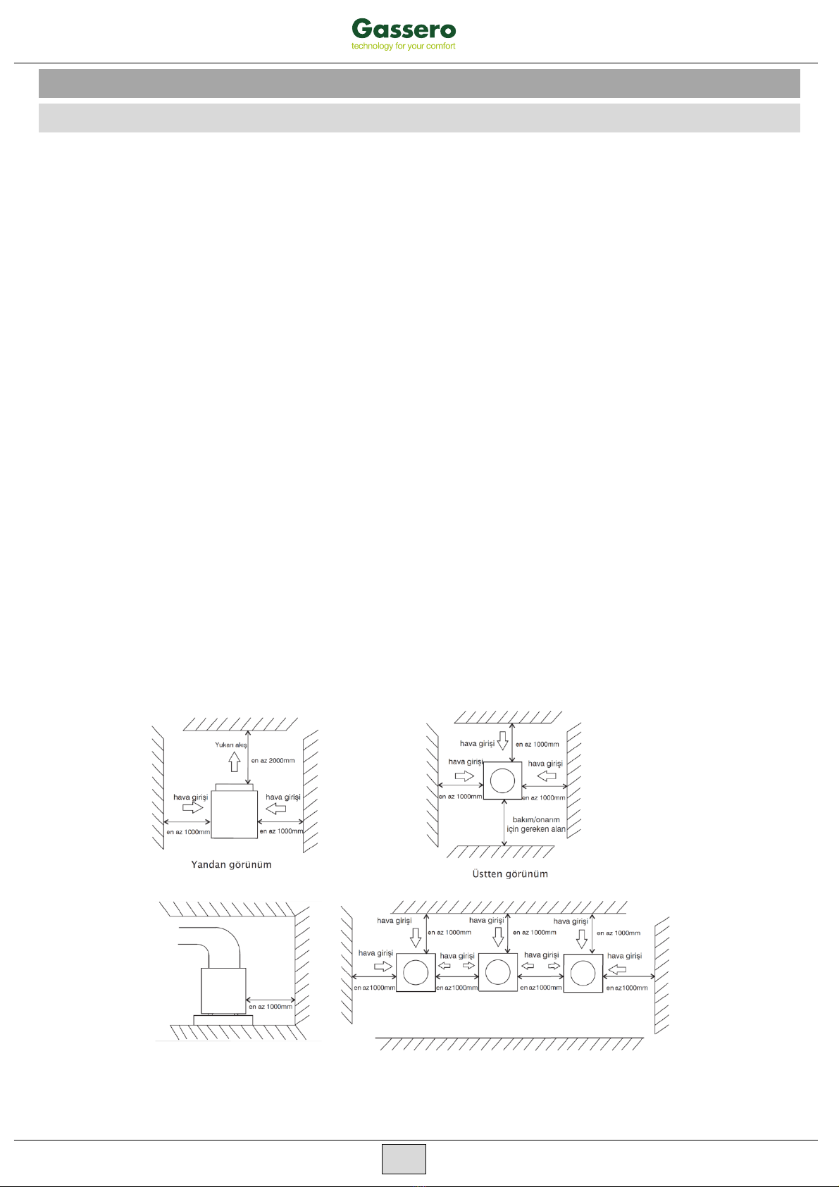
The installation should be carried out at the place of unobstructed ventilation of the air outlet.
(The inlet and outlet of the air blower are illustrated in the following diagram). The installation
space should be referred as follows:
▲An exhaust duct should be
connected to the heat pump air outlet
if there is a barrier above the air outlet.
▲A certain distance should be kept among the heat pumps
and it should be at least 1 meter when several heat pumps
are installed side by side.
9. INSTALLATION

15
9.2. WATER TANK INSTALLATION
The water tank should be put in a place where ambient temperature is higher than 0ºC.
It can be installed either outdoors or on the roof-top (some elements such as the size of water tank
and the bearing capability of the building should be considered). Installation on roof-top should be
based on support such as crossbeam or pillar.
The water tank should not be installed lower than the foundation of the heat pump; It is suggested
to install the heat pump, the water tank and the circulation pump at the same level. Besides, the
height difference between the heat pump and the water tank should be no more than 2meters,
when water tank position is higher than that of the heat pump.
Do not install the water tank in apollutive or corrosive area.
The reasonable allocation of the heat pump and water tank volume should deploy by 1/0.6 as
maximum. Please refer to the following:
MODEL GSR-20-HC GSR-30-HC GSR-38-HC GSR-45-HC GSR-63-HC
TANK VOLUME 3000 L 4500 L 6000 L 8000 L 12500 L
9.3 WATER PIPING INSTALLATION
Drainpipe and overflow pipe should be installed near the gutter or the sinkhole for draining water more
efficiently. Discharge valve is necessary on the drainpipe.
Service valve needs to be installed before the magnet-valves on the system pipeline for further
inspection.
The pressure of the water outlet should be between 0.3MPa and 0.6MPa.
It is recommended to use metal pipeline such as stainless steel pipes, internal-plastic pipes,
internal stainless steel pipes or copper pipes etc; Telescopic issue of the pipeline between heat
pump unit and water tank should be considered if plastic pipeline such as PPR pipe and ABS pipe
etc. is used.
In winter, heat preservation may need to be carried out for the water supply valve and the stop
valve of the system (according to local ambient temperature) for avoiding icing of the water supply
pipe and the valves.
Keep the water pipes straight and the pipeline allocation reasonable; Reduce pipe turnings as
many as possible to reduce water resistance.
Prevent the pipeline and the connectors from water leakage.
The water pressure bearing capability of each part of the piping system should be tested after the
installation is finished; Drainage should be done to create aclean interior system.
Measures of heat preservation for the hot water pipeline need to be conducted after assuring no
water leakage.

16
Isıtma Devresi
If this appliance is
installed for house heating
(or cooling), to ensure the
appliance to operate
correctly, we recommend
the installation of a buffer
tank in any case, the
buffer tank is not only
installed as hydraulic
speparator for volume
flow in the heat pump
circuit, but primarily as
the heat source for
defrosting the evaporator.
Shut-Off Valve
Solenoid Valve
Check Valve
Elec Heater
Water Pump
Y-Shape Filter
Flow Switch
Heat Pump
Controller
Heat Pump
Dinning Hall
Guest Room
Sauna Room
Water
Pump
Filter
Filter Solenoid Valve
Flow Switch
(can omit)
Drainage
Water Tank
Check Valve Elec Heater
(can omit)
Heating / Cooling Circuit
1Heat pump
2Heat pump controller
3Butffer tank
4Circulation pump
5Non-return valve
6Shut-off valve
7Drain valve
8Filter
9Expansion vessel
10 Safety pressure valve
11 Air vent valve
12 Pump (heating or cooling circuit)

17
Model
Power
Cable
Water
Pump
Solenoid
Valve
Sensor
GSR-20-HC
5x4mm² 3x1,5mm² 3x1,0mm² 2x0,35mm²
GSR-30-HC
5x6mm² 3x1,5mm² 3x1,0mm² 2x0,35mm²
GSR-38-HC
5x6mm² 3x1,5mm² 3x1,0mm² 2x0,35mm²
GSR-45-HC
5x6mm² 3x1,5mm² 3x1,0mm² 2x0,35mm²
GSR-63-HC
5x10mm² 3x2,5mm² 3x1,0mm² 2x0,35mm²
9.4. RECOMMENDED WIRE SPECIFICATION
9.5. WIRE CONTROL INSTALLATION
The wired controller is originally fixed on the maintenance door of the machine; please refer to below steps if
you want to install it on the wall:
1. Take down the controller from the machine. Please pay attention that the communication wire is
connected with the circuit board, separate them from where they match.
2. Use a screwdriver to open the clip as picture 1, separate the controller as 2 parts, as picture 2
3. On the wall that you are going to install the controller, drill 2 holes at a level parallel to the sight line as
picture 3.
The hole distance is 60mm, diameter is 8mm.
1. Place the plastic screws of the enclosure into the hole, and use the tapping screw (ST4*16 D-1)
enclosed to fix the back cover of controller on the wall, as picture 4
2. Match the front and back covers perfectly, as picture 5, make sure that it is fixed firmly on the wall.
3. Connect the communication wire well.
Arka Kapak Ön Kapak
İletişim Kablosu Çıkışı
12
34
5
6
The Back Cover The Front Cover
Outlet of the communication wire
Attention:
Please don't use keen-edged things to hit the controller face and keys, or it may cause damage.
When the controller is fixed on the wall, don't pull the communication wire, or it may cause poor contact.

18
10. COMMISSIONING
10.1. PREPARATION BEFORE COMMISSIONING
Inspection on the heat pump
Check if the outside case and the inside system of the heat pump have been damaged during the
transportation. Check if there is still air inside the water system. If yes, use the air vents on the water system
and the circulation pumps, to discharge the air out.
Inspection on the power source system
Make sure the power source is accordance with the specification in the manual or on the heat pump
nameplate. Make sure all power connections and control circuit are in place. Make sure the wiring , grounding
and all terminals are strong and reliable.
Inspection on the piping system
Check if the water piping system, including water supply pipe, return water pipe, pressure gauge,
thermometer, valves, water level switch are installed correctly. Please open all the valves which should be
opened, and close all that should be closed before the commissioning. Make sure the heat preservation
of the water system is in good condition.
10.2. COMMISSIONING
The commissioning should be carried out by profession.
Comprehensive inspection of the entire system should be identified as meeting the requirements, and
the water level inside the tank is higher than the cycling heating outlet and the water outlet, before the
commissioning.
After power on the electricity, turn on the heat pump by pressing the on/off key on the wire control panel.
Please check if the fan and the circulation pump are running in the right direction. If not, shut down the
power supply and adjust the phase-order. Make sure the compressor current is in normal range, without
abnormal sound.
Check the circulation pump and all other parts meet the requirement. The whole system can be put into
use after the pre-operation for aperiod of time.

18
11. CONTROL PANEL
ON/OFF
Press the key for 1second to turn on or turn off the unit as the controller is unlocked. Press
the key to return the main interface as in any other settings. Press the key
for 5seconds to unlock as the controller is locked.
FUNCTION
In the main interface, the key is for status query.
UP / DOWN
Page up and down, query or modify parameters.
Query or set parameters together with “Function” key.
Press “+” and “-”to set the water temperature of current mode as the unit is turned on.
CLOCK AND TIMER KEY
Press “timer” for 5 seconds to set clock.
Long press “time” key to enter timer setting, together with “+”and “-”to set ON/OFF
timer , totally two ON/OFF periods can be set.

19
11.2. OPERATION
Lock and unlock
Press “ON/OFF”key for 5seconds to unlock the
controller after abeep of the buzzer.
Lock automatically after 60 seconds without operation.
Homepage
Lock keys
Unlock keys
Within 60 seconds without operation
5 Secconds
℃℃
℃℃
℃℃
℃℃
OFF state
ON state
1seconds
℃℃
1seconds
OFF state
℃℃
7.2.2 ON/OFF switch
Water temperature setting
When the heat pump is switched on, Press “+” and
“ -” to set the water temperature of current mode as
the unit is turned on.
Mode switch
Press “+” for 5seconds to switch the mode.
7.2.5 Manual defrosting
Press “-“ for 5seconds to enter manual defrosting
(coil temp >defrosting quit temp (H6))
To quit manual defrosting, long Press “ON/OFF”key
or wait till the defrosting time reaches the maximum
defrosting duration (parameter H5)
Heating mode
Cooling mode
℃℃
5seconds
℃℃
Homepage
Manual defrosting
Quit defrosting
5 seconds
5seconds (or defrosting exit condition achieved)
℃℃
℃℃
℃℃
This manual suits for next models
4
Table of contents
Other gassero Heat Pump manuals


Popular Heat Pump manuals by other brands


American Standard
American Standard 4A7A5 Installer's guide

ClimateMaster
ClimateMaster Ultra Classic VT 072 Installation, operation & maintenance instructions

Lochinvar
Lochinvar AMICUS HT Series Installation, commissioning and service manual

Robur
Robur GAHP A indoor Instructions for installation, use and maintenance manual

Carrier
Carrier 50ZHB Owner's information manual

Cool Energy
Cool Energy inverPool CE-iVP6 Installation and user guide