Gatan K2 Summit User manual

K2 SummitTM and K2 BaseTM Direct
Detection Camera
User’s Guide
Model Number 1000, 1000.S, 1000.B and 1000.U
Document Part Number: 1000.40004
Revision 01
Gatan, Inc.
5794 W. Las Positas Blvd
Pleasanton, A 94588
Tel. +1 925-463-0200
Fax. +1 925-463-0204

K2 Summit and K2 Base Direct Detection Camera User's Guide
2
Table of Contents
Preface 6
About this Guide........................................................................................................................6
Conventions ...............................................................................................................................6
Disclaimer..................................................................................................................................6
Copyright and Trademarks ........................................................................................................6
Returns.......................................................................................................................................7
Support.......................................................................................................................................7
Introduction 8
Why Silicon APS and Counting are Good.................................................................................8
K2 Base and K2 Summit Configurations.................................................................................10
Super-Resolution Description and Overview of Performance Benefits ..................................10
Linear Accumulation Setup Mode...........................................................................................13
Radiation Hardness and Expected Lifetime.............................................................................13
Getting Started with the K2 Direct Detection System 14
Power on Sequence for K2 Base..............................................................................................14
Power off Sequence for K2 Base.............................................................................................15
Power on Sequence for K2 Summit.........................................................................................15
Power off Sequence for K2 Summit ........................................................................................17
Setting Temperature.................................................................................................................18
Anneal Cycle............................................................................................................................18
K2 Summit Imaging Modes.....................................................................................................19
Updating Reference Images.....................................................................................................20
K2 Summit Reference Images...........................................................................................21
K2 Base and K2 Summit Linear .................................................................................21
K2 Summit Counted and K2 Summit Super-Resolution ............................................24
Updating Summit Hardware Background Reference Image Only..............................28
Updating Reference Images for K2 Summit Counted and Super-Resolution Modes .......28
Base Gain Reference Collection .................................................................................28
Key Points to Ensure Optimum Operation .................................................................28
Other Recommendations ...................................................................................................29

K2 Summit and K2 Base Direct Detection Camera User's Guide
3
Operation of the K2 Direct Detection System 30
K2 Imaging ..............................................................................................................................30
Linear Mode Operation .....................................................................................................30
View Mode .................................................................................................................30
Counted and Super-Resolution Mode Operation ..............................................................30
Dose Rate Considerations...........................................................................................30
Dose-Rate Monitor .....................................................................................................31
Shutter Delay Setup...........................................................................................................31
Defect Correction ..............................................................................................................32
Binning and Subareas........................................................................................................33
Dose Fractionation ............................................................................................................33
Setup ...........................................................................................................................34
Shutter Configuration........................................................................................................35
Shutter Connections and Signal Configuration...........................................................36
Base Camera: Linear Mode Operation..............................................................................36
Switching Between Base and Summit Modes...................................................................37
Care of Detector ................................................................................................................38
Temperature................................................................................................................38
Anneal Cycle ..............................................................................................................38
Auto Retraction...........................................................................................................38
Insertion Indicators............................................................................................................39
Dynamic Sensor Protection (DSP) Operation..........................................................................39
Software...................................................................................................................................40
Overview: Control of K2 Camera within DM...................................................................41
Screenshot of DM Display for K2 Camera.................................................................41
Magnification Correction/Calibration......................................................................................41
Low Magnification............................................................................................................42
High Magnification ...........................................................................................................44
Specifications...........................................................................................................................46
Compatibility with Other Gatan Cameras and GIF...........................................................47
Addendum 48
Ensuring Validity of Defect Corrections .................................................................................48

K2 Summit and K2 Base Direct Detection Camera User's Guide
4
List of Figures
figure 1-1.Monte Carlo simulations of electron interaction with direct and indirect camera
system.....................................................................................................................9
figure 1-2.Overview of the K2 Base and K2 Summit systems .............................................10
figure 1-3.Overview of electron detection process in K2 Base and K2 Summit ..................12
figure 1-4.K2 digitizer...........................................................................................................14
figure 1-5.TEC Controller (top) and K2 Summit Processor (bottom) ..................................15
figure 1-6.K2 digitizer...........................................................................................................16
figure 1-7.DigitalMicrograph interface during startup of K2 Summit system......................16
figure 1-8.DigitalMicrograph interface during shutdown of K2 Summit system .................17
figure 1-9.Camera menu........................................................................................................18
figure 1-10.K2 Sensor temperature.........................................................................................18
figure 1-11.K2 Direct Detection palette: Linear mode ...........................................................19
figure 1-12.K2 Direct Detection palette: Counted mode ........................................................20
figure 1-13.K2 Direct Detection palette: Super-Resolution mode..........................................20
figure 1-14.Option to skip gain reference collection...............................................................21
figure 1-15.Suggested gain reference exposure factor............................................................21
figure 1-16.Settings for K2 Summit linear mode gain reference ............................................22
figure 1-17.Expert Mode settings............................................................................................22
figure 1-18.Gain reference exposure factor recommendations ...............................................23
figure 1-19.Beam intensity recommendation..........................................................................23
figure 1-20.Settings for intensity and number of frames to average .......................................24
figure 1-21.Image overwrite confirmation..............................................................................24
figure 1-22.Linear mode gain reference success message ......................................................24
figure 1-23.Gain reference collection option ..........................................................................24
figure 1-24.Hardware dark reference option...........................................................................25
figure 1-25.Settings for K2 Summit linear mode gain reference ............................................26
figure 1-26.Expert Mode settings............................................................................................26
figure 1-27.Beam adjustment reminder...................................................................................27
figure 1-28.Beam intensity recommendation..........................................................................27
figure 1-29.Settings for intensity and number of frames to average .......................................27
figure 1-30.Linear mode gain reference success message ......................................................27
figure 1-31.Update HW Dark Reference button .....................................................................28
figure 1-32.View Mode dialog................................................................................................30

K2 Summit and K2 Base Direct Detection Camera User's Guide
5
figure 1-33.Current dose rate on camera.................................................................................31
figure 1-34.Current dose rate and total dose accumulated on the specimen per image ..........31
figure 1-35.Pre-Dose Delay setting.........................................................................................31
figure 1-36.Advanced View Options, settling delay option....................................................32
figure 1-37.Comparison of a dose fractionated dataset acquired and summed with alignment
(top right) and without per frame alignment (lower left) .....................................34
figure 1-38.Exposure time setting...........................................................................................34
figure 1-39.Dose Fractionation mode settings ........................................................................35
figure 1-40.Shutter settings tab ...............................................................................................36
figure 1-41.Auto Retraction Delay setting ..............................................................................39
figure 1-42.Gatan logo, and Camera Inserted setting..............................................................39
figure 1-43.Typical DM setup DigitalMicrograph..................................................................41
figure 1-44.Example of marking a known distance during magnification calibration............42
figure 1-45.Magnification calibration instructions..................................................................42
figure 1-46.Calibration settings...............................................................................................43
figure 1-47.Calibration confirmation ......................................................................................43
figure 1-48.Microscope Calibration dialog.............................................................................43
figure 1-49.High-resolution image of sample to be used in the magnification calibration.....44
figure 1-50.Distance between peaks in the calculated diffractogram .....................................45
figure 1-51.Calibration instructions ........................................................................................45
figure 1-52.Calibration settings...............................................................................................46

K2 Summit and K2 Base Direct Detection Camera User's Guide
6
Preface
About this Guide
This K2™ User’s Guide provides a brief description of the camera’s operating principles,
instructions on how to use the camera, and an introduction to imaging in
DigitalMicrograph™. The intent of this guide is to help the user become proficient and
comfortable with the camera, DigitalMicrograph software and to correctly acquire images
from the camera. Additionally it should give the user an understanding of the working
principles of the camera and allow for easy troubleshooting.
Conventions
The following typographical conventions are used for special comments:
SPECIAL NOTE: Recommendations for getting the best performance from the
equipment.
CAUTION: This is the CAUTION symbol; it alerts you to potential hazards that require you
to consult the documentation in all cases where this symbol is marked.
WARNING: Alerts to indicate when something may have the potential to cause damage to
the equipment or fail to operate correctly if the instructions are not followed.
Disclaimer
Gatan, Inc., makes no express or implied representations or warranties with respect to the
contents or use of this manual, and specifically disclaims any implied warranties of
merchantability or fitness for a particular purpose. Gatan, Inc., further reserves the right to
revise this manual and to make changes to its contents at any time, without obligation to
notify any person or entity of such revisions or changes.
Copyright and Trademarks
© 2012 Gatan, Inc. The Gatan logo is a registered trademark of Gatan, Inc. K2, K2 Summit,
K2 Base, and DigitalMicrograph are trademarks of Gatan, Inc.
All rights reserved. No part of this publication may be reproduced, stored in a retrieval
system, or transmitted, in any form or by any means, electronic, mechanical, photocopying,
recording, or otherwise, without the prior written permission of Gatan, Inc.
The text and graphics are for the purpose of illustration and reference only. The specifications
on which they are based are subject to change without notice.

K2 Summit and K2 Base Direct Detection Camera User's Guide
7
Returns
In the event that the instrument must be returned to the factory, please request a Returned
number must appear on all shipping documents to ensure that proper actions will be taken to
repair or replace the instrument.
Support
Gatan, Inc. provides free technical support via phone, fax, and electronic mail. To reach
Gatan technical support, contact the facility nearest you, or send an email to
Please consult the Customer Service section of the Gatan website at www.gatan.com for the
latest contact information.

K2 Summit and K2 Base Direct Detection Camera User's Guide
8
Introduction
IMPORTANT: For Regulatory Compliance and Safety information and instructions
please refer to the Regulatory Pamphlet provided with this product. Review
this document in full before installing and operating this product.
The K2 Summit™ Direct Detection Camera is a new type of camera for TEM. The camera
contains a direct detection transmission CMOS detector, which gives the highest resolution
images of any electron-imaging sensor available today. The camera runs in a mode constantly
collecting images at 400 frames per second. The camera then, through a high-bandwidth link,
passes these frames at full speed to dedicated high-throughput hardware designed for the
express purpose of processing these images in real time. By collecting and processing full-
frame images so quickly the detector can identify and record individual electron events
(counting) as they reach the sensor. By counting every single electron event, the camera can
eliminate the background noise typically seen in devices that simply read out the charge
deposited by an electron striking a piece of silicon. By removing this source of noise, the
camera can offer higher image quality and sensitivity than previously available in an electron-
imaging device.
This device is also capable of operating in a Super-Resolution mode. In this mode, the sensor
is able to localize the electron event with sub-pixel accuracy, effectively doubling the number
of pixels available for imaging (from 3838 x 3710 to 7676 x 7420). Again the processing is
all done on full frames in real time as the images are collected. In addition, the camera
employs a pixel design giving radiation hardness 10x greater than any other direct-detection
sensor available (pixel lifetime of >5 billion electrons). K2 Summit also allows Linear read
mode (used on K2 Base™) for high-dose applications.
Why Silicon APS and Counting are Good
Direct Detection sensors are derived from Active Pixel Sensor (APS) technology developed
for digital cameras and cell phones. Like a CCD, an APS is an integrated circuit containing
an array of pixels. But unlike a CCD, readout does not require pixel-to-pixel charge transfer.
Each pixel contains a photo detector and active amplifier that is addressed and read-out
individually. The K2 Direct Detection APS is designed using proprietary design and layout
techniques that make it radiation resistant enough to detect electrons without significant
damage to the sensor. K2 Direct Detection APS is based on CMOS semiconductor
technology and produced at commercial semiconductor foundries with manufacturing of
more advanced (smaller) nodes resulting in increased radiation resistance.
Direct Detection was used in high-energy particle physics and other fields before coming to
EM. A major challenge for EM uses is that energy and charge deposited by the high-energy
electrons quickly damage most sensor types, causing a rapid deterioration of the image
quality. CCD sensors have been used for direct detection, although only for a short period of
time before failure. Early development (“first generation”) EM Direct Detectors had poor
radiation hardness, meaning poor ease of use and the need for a second “set up” camera for

9
all op
e
fabric
a
fi
g
ur
e
A Dir
e
in the
eleme
n
scintil
l
of ele
c
reduci
the pr
i
this b
a
The
m
to use
Direct
camer
a
electr
o
Anoth
distor
t
lenses
The D
noise
o
from
o
counti
The e
l
electr
o
natura
drama
t
frequ
e
K2 Summit
e
rations othe
r
a
tion choices
e
1-1. Mon
t
cam
e
e
ct Detection
sensor’s sup
p
n
t, dramatica
l
l
ato
r
s are use
c
trons from t
h
n
g resolutio
n
i
mary electro
n
a
ckscattering.
m
uch smaller
P
much smalle
r
Detection c
a
a
s as the sig
n
o
n is large rel
er advantage
t
ion, fixed pa
t
.
etective Qua
n
o
f the camer
a
o
ne electron t
o
n
g models a
n
ectron count
i
o
n with a dis
c
l variation in
t
ically lifting
e
ncies.
and K2 Base
r
than the fin
a
which signif
i
t
e Carlo sim
u
e
ra s
y
stem
sensor only
r
p
ort is not de
t
l
ly reducing
t
d. In a first g
e
h
e sensor bul
k
n
. Advanced
D
n
s to pass thr
o
P
SF for a tra
n
r
pixels, 5 μ
m
a
meras have
a
n
al from the n
u
ative to the r
e
of Direct De
t
t
terns, and g
a
n
tum Efficie
n
a
electronics
a
o
the next. T
h
n
d modes; the
i
ng mode of
K
c
rete count. T
h
energy depo
s
the Detectiv
e
Direct
D
etect
i
a
l acquisition
i
cantly incre
a
u
lations of e
l
r
ecords the si
g
t
ected. Silico
n
t
he PSF relati
v
e
neration “b
u
k
back to the
t
D
irect Detect
i
o
ugh the sen
s
n
smission sys
t
m
in case of
K
a
superior sig
n
u
mber of ele
c
e
ad noise of t
h
t
ection is the
a
in variations
n
cy (DQE) o
f
a
nd by large
v
h
is is also tru
e
ir ultimate p
e
K
2 Summit r
e
h
e benefit of
s
ited by elect
r
e
Quantum E
f
i
on Camera
U
of low dose
d
a
se radiation
h
l
ectron inte
r
g
nal deposit
e
n
itself is a re
ve to traditio
n
u
lk” Direct D
e
t
op (active) l
a
i
on sensors, l
i
s
or, with no
“
tem such as
K
K
2, yielding
m
n
al-to-noise
r
c
tron hole pa
i
he sensor ele
c
absence of a
associated w
i
f
traditional c
a
v
ariations in
t
e
for direct d
e
e
rformance is
e
places the a
n
counting is t
h
r
ons impingi
n
fficiency (D
Q
U
ser's Guid
e
d
ata. K2 imp
l
h
ardness.
r
action with
d
e
d in its top l
a
latively low
a
n
al EM cam
e
et
ector there
a
yer, increas
i
i
ke K2, are b
a
“
bulk” suppo
r
K
2 allows a
D
m
any more pi
x
r
atio relative
t
i
rs detected f
r
ctronics.
number of i
m
ith scintillato
a
meras is hel
d
t
he amount o
f
e
tection cam
e
limited by t
h
n
alogue signa
h
at it rejects
r
n
g on the det
e
Q
E) of the de
t
l
ements desi
g
d
irect and in
a
yer; energy
d
a
tomic numb
e
e
ras where ph
is still backs
c
i
ng the PSF a
n
a
ck-thinned
a
r
t and thus m
i
D
irect Detecti
x
els per unit
o
t
o traditional
r
om each pri
m
m
age artifacts
rs and fiber
o
d
back by th
e
f
energy dep
o
e
ras and for
n
h
e noise in th
e
l from each
p
r
ead noise an
d
e
ctor, thereb
y
t
ector across
g
n and
direct
d
eposited
e
r (Z)
h
osphor
c
attering
n
d
a
llowing
i
nimize
on sensor
o
f area.
EM
m
ary
such as
o
ptics or
e
read
o
sited
n
on-
e
system
p
rimary
d
the
y
all spatial

10
K2 B
a
Supe
r
Bene
f
a
se and
The
K
offers
detect
i
electr
o
The
K
and P
C
traditi
o
fi
g
ur
e
The
K
and P
C
that is
combi
high r
a
syste
m
r
-Resol
u
f
its
The
K
infor
m
such t
h
incom
K2 Summit
K2 Su
m
K
2 Direct Det
e
the performa
i
on camera,
a
o
n counting a
n
K
2 Base Direc
t
C
which is ru
n
o
nal charge i
n
e
1-2. Ove
rv
K
2 Summit Di
r
C
, but what
m
responsible
f
n
ation of the
a
te that enabl
m
.
u
tion D
e
K
2 Summit S
u
m
ation limit d
e
h
at the PSF i
s
ing electron
d
and K2 Base
m
mit Co
n
e
ction camer
a
nce improve
m
a
nd the K2 S
u
n
d Supe
r
-Re
s
t
Detection c
a
n
ning Digital
n
tegration m
o
rv
iew of the
K
r
ect Detectio
n
m
akes the K2
f
or counting
t
very fast rea
d
es the uniqu
e
e
scripti
o
u
pe
r
-Resoluti
o
e
fined by the
s
slightly lar
g
d
eposits sign
a
Direct
D
etect
i
n
figurat
i
a
system com
e
m
ent you wo
u
u
mmit, which
s
olution mod
e
a
mera syste
m
Micrograph.
o
de that we c
a
K
2 Base and
n
camera sys
t
Summit uniq
u
t
he individua
l
d
out with the
e
Counted an
d
o
n and
O
o
n mode take
physical pix
e
g
er than the 5
a
l in a small
c
i
on Camera
U
i
ons
e
s in two co
n
u
ld expect fr
o
includes the
e
s of operati
o
m
includes th
e
The K2 Bas
e
a
ll “Linear”
m
d
K2 Summit
t
em also incl
u
u
e is that it i
n
l
electrons as
ability to co
u
d
Supe
r
-Reso
l
O
vervie
w
s counting f
u
e
l size. The
K
μm physical
c
luster of pix
e
U
ser's Guid
e
n
figurations,
t
o
m a second-
g
dedicated ha
r
o
n.
e
camera itsel
f
e
system only
m
ode.
s
y
stems
u
des the cam
e
n
cludes a de
d
they strike t
h
u
nt individua
l
l
ution modes
w
of Per
f
u
rther and sur
p
K
2 sensor wa
s
pixel size. A
s
e
ls. The high
-
t
he K2 Base
w
g
eneration di
r
r
dware to en
a
f
, and digitiz
e
operates in t
h
e
ra, the digiti
z
d
icated proce
s
h
e sensor. It i
s
l
electrons at
available wi
t
f
orman
c
p
asses the th
e
s
carefully de
s
s
a result eac
h
-
speed K2 S
u
w
hich
r
ect
a
ble the
e
r unit
h
e
z
er unit
s
sing unit
s
the
the same
t
h this
c
e
e
oretical
s
igned
h
u
mmit

K2 Summit and K2 Base Direct Detection Camera User's Guide
11
electronics is able to recognize each electron event (at 400 frames per second) and find the
center of that event with sub-pixel precision.
The net effect is a quadrupling of the effective number of pixels (pushing beyond the Nyquist
information limit to even higher resolution), as well as a further improvement of the DQE
(and MTF). Practically, this means that the field of view can be increased for the same end
resolution allowing the researcher to capture much more data per image.
As a point of interest, Counted mode uses the same processing algorithm as Super-
Resolution, but bins pixels 2x2 in the camera to support faster live viewing speeds and a more
compact data format. The decision of which mode to use should be based on user criteria and
experiments on an application by application basis. This fact is the reason that a single Super-
Resolution acquisition is all that is needed to produce software gain references for both
Super-Resolution and Counted modes.
The Need for Speed: Electron counting is only possible if the camera can read-out images
fast enough to “see” the individual electrons “raining” down on the sensor. K2 was
specifically designed to count at a typical Cryo EM dose rate of 10-20 e-/pixel/s allowing a
20 e-/Å2 low dose image to be recorded in 1-2 s (at a magnification equivalent to 1 Å/pixel).
To do so the K2 Summit reads out at a rate of 400 full frames/s (5.7 Gigapixels per second!)
using a highly parallelized, high-speed architecture able to process image data at 80 Gb/s.
Much of the discussion surrounding Direct Detection cameras focuses on only the
performance improvements of the sensor relatively to traditional CCD cameras. What this
misses is that it is not possible to routinely acquire images in Counted mode unless the data
processing pipeline is in place to handle this massive volume of data in real time.
We like to say that K2 is “The One That Counts” because counting is what gives the biggest
performance boost to the K2 camera. K2 is the only Direct Detection EM camera specifically
designed for counting and able to do so in a useful way.
Counting (K2 Summit only):
Individual primary electrons are counted in-line in the Summit processor on a pixel-by-
pixel, frame-by-frame basis.
The electron Counted mode of K2 Summit replaces the analogue signal from each
primary electron with a discrete count.
The benefit of counting is that it completely rejects the read noise and dramatically lifts
the Detective Quantum Efficiency (DQE) of the detector across all spatial frequencies.

12
fi
g
ur
e
Supe
r
E
a
th
e
re
s
T
h
th
e
T
h
p
h
A
s
T
h
fr
a
T
h
N
y
th
e
P
r
al
l
K2 Summit
e
1-3. Ove
rv
r
-Resolution
a
ch primary
e
e
electron’s l
a
s
olution bey
o
h
e K2 Summ
i
e
oretical info
h
e K2 sensor
h
ysical pixel
s
s
a result eac
h
h
e high-spee
d
a
mes per sec
o
h
e net effect i
y
quist infor
m
e
DQE (and
M
r
actically, thi
s
l
owing the re
s
and K2 Base
rv
iew of elec
t
Counting (
K
lectron’s sig
n
a
nding coord
i
o
nd the numb
e
i
t Supe
r
-Res
o
rmation limi
t
was carefull
y
s
ize.
h
incoming e
l
d
K2 Summit
o
nd) and find
s a quadrupli
n
m
ation limit to
M
TF).
s
means that
t
s
earcher to c
a
Direct
D
etect
i
t
ron detecti
o
K
2 Summit o
n
n
al cloud is a
n
i
nates with s
u
e
r of pixels i
n
o
lution mode
t
t
defined by t
h
y
designed su
c
l
ectron depos
i
electronics i
s
the center o
f
n
g of the eff
e
even higher
t
he field of vi
e
a
pture much
m
i
on Camera
U
o
n process i
n
n
ly):
n
alyzed in th
e
u
b-pixel accu
r
n
the sensor.
t
akes counti
n
h
e physical p
c
h that the P
S
its signal in
a
s
able to reco
g
f
that event w
i
e
ctive numbe
r
resolution),
a
ew can be in
c
m
ore data pe
r
U
ser's Guid
e
n
K2 Base a
n
e
Summit pr
o
r
acy. This te
c
n
g further an
d
ixel size.
S
F is slightly
a
small cluste
r
g
nize each el
e
i
th sub-pixel
p
r
of pixels (p
u
a
s well as a f
u
c
reased for t
h
r
image.
n
d K2 Sum
m
o
cessor to det
e
c
hnique exte
n
d
surpasses th
e
larger than t
h
r
of pixels.
e
ctron event
(
p
recision.
u
shing
b
eyon
u
rther improv
h
e same end r
e
m
it
e
rmine
n
ds the
e
h
e 5 μm
(
at 400
n
d the
ement of
e
solution

K2 Summit and K2 Base Direct Detection Camera User's Guide
13
Linear Accumulation Setup Mode
Linear mode is the traditional energy-integrating read out mode that captures the total
integrated signal level in each pixel just like a CCD camera does. Individual frames can be
summed for an effectively unlimited dynamic range.
In K2 Base and K2 Summit linear mode charge is collected, integrated during the exposure,
and read out to provide the image. Sensor electron charge proportional to the total energy
deposited by the incoming primary electron is accumulated. This mode benefits from Direct
Detection’s improved DQE arising from the transmission detector and inherent higher
conversion efficiency. When not counting, there is no requirement to keep charges separated.
This mode is good for higher dose images and allows for dose rates up to 400 times higher
than in Counted mode, and somewhat higher than is practical even in traditional CCD
cameras. Of course, if higher doses are used, the user must remain aware of the lifetime total
dose capability of the camera and avoid unnecessary exposure of the camera to the beam.
Radiation Hardness and Expected Lifetime
Minimize exposing the CMOS sensor to the electron beam when the camera is not in
use. Based on the results to date, the lifetime of the K2 detector is estimated at 5 billion
e-/pixel. Considering exposure rates of 100 electrons/pixel/second, if the sensor were exposed
continuously for 24 hours a day every day, the expected lifetime would be well over 1 year.
The camera employs a pixel design that is 10 times more resistant to incident electron
damage as compared with other direct-detection sensors. The extremely short exposure time
coupled with the event discrimination of Counted mode confers an additional approximately
10 times immunity to radiation.
The sensor can be damaged and marked by a bright beam. Use caution with intense
beams and bright spots. Do not leave the sensor exposed to the beam when changing
magnification levels or spot sizes. These can create brief intense spots. Annealing may be
able to reduce or remove minor beam spots.
Direct Detection cameras receive the incoming electrons directly to the imaging sensor, and
in the case of K2™ can detect them in several modes. This Direct Detection eliminates the
need for scintillator and fiber optics or lenses and greatly reduces Point Spread Function
(PSF). Furthermore, in Gatan’s Counted modes, noise can be essentially eliminated,
particularly because with Gatan’s transmission sensor, there are no scattered electrons re-
entering the detector from below.
K2 Summit and K2 Base Direct Detection Camera User's Guide
14
Getting Started with the K2 Direct
Detection System
Power on Sequence for K2 Base
To start from the power off:
1. Close DM if it is open (or power on the PC if it is off).
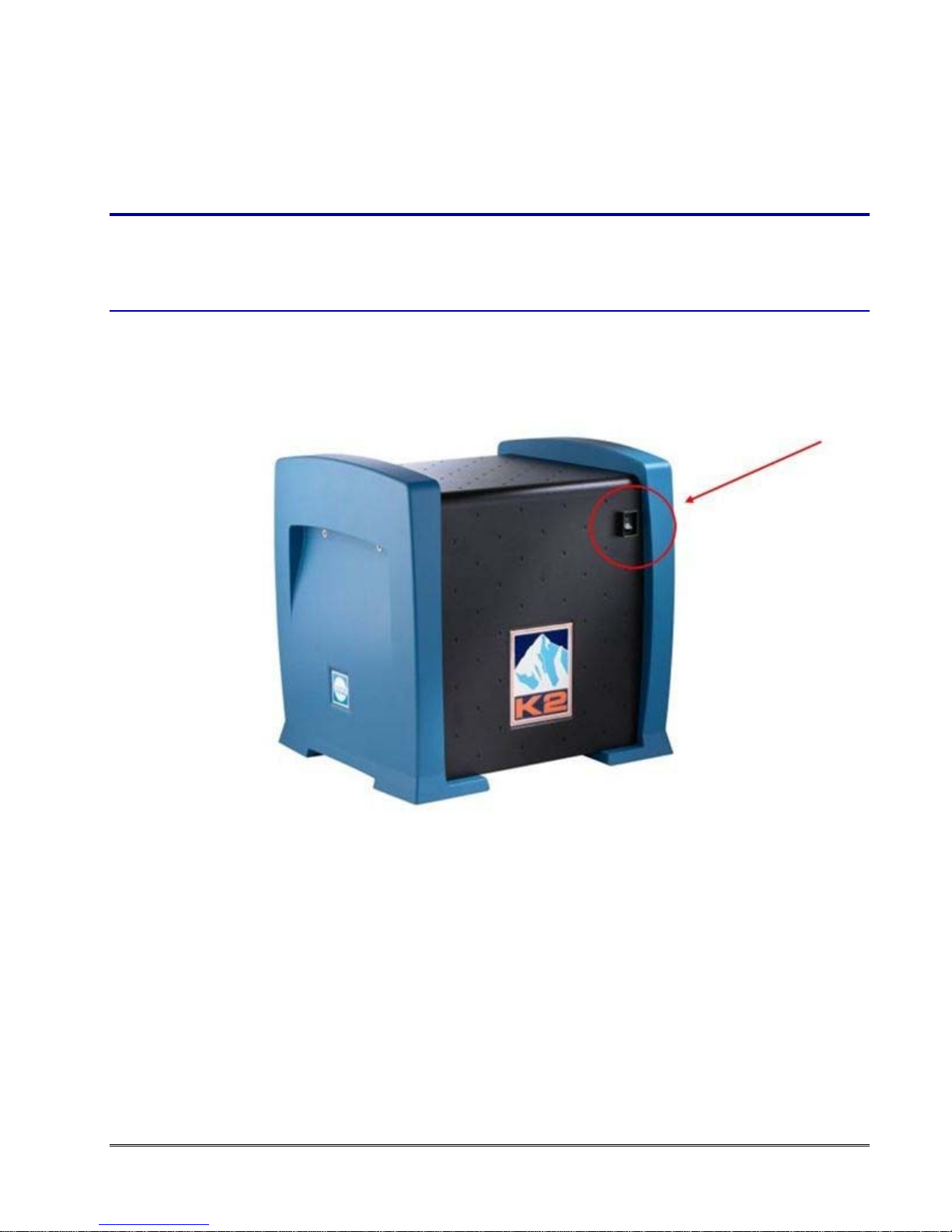
2. Turn on the K2 digitizer (blue K2 box near the camera and TEM).
figure 1-4. K2 digitizer
3. Wait at least 3 minutes after powering on the K2 digitizer.
4. Launch DigitalMicrograph (DM).
5. Click the setting button (hammer/wrench) (#1, Figure 1-7, page 16) in the K2 Direct
Detection palette.
6. Click the System ON button. Wait for the system to finish turning on.

15
Powe
Powe
r off Se
q
Under
down
t
To co
m
1. In
2. C
l
3. C
l
4. T
u
5. T
u
r on Se
q
To st
a
1. C
l
2. T
u
3. T
u
fi
g
ur
e
4. T
u
K2 Summit
q
uence
normal circ
u
t
he K2 came
r
m
pletely po
w
DM: Click t
h
l
ick the Syst
e
l
ose DM.
u
rn off K2 di
g
u
rn off the P
C
q
uence
f
a
rt from the
p
l
ose DM if it
u
rn on power
u
rn on the po
w
e
1-5. TEC
u
rn on the K
2
and K2 Base
for K2
B
u
mstances, y
o
r
a completel
y
w
er down th
e
h
e settings b
u
e
m OFF
b
utt
o
g
itizer (blue
b
C
if desired.
f
or K2
S
p
ower off:
is open (or p
o
to the Ther
m
w
er switch o
n
Controller
(
t
o
2
digitizer (bl
u
Direct
D
etect
i
B
ase
o
u can leave t
h
y
.
e
K2 camera
u
tton (hamme
o
n. Wait abo
u
b
ox).
S
ummit
o
wer on the
P
m
o Electric C
o
n
the back of
t
o
p
)
and K2
S
u
e K2 box ne
a
i
on Camera
U
h
e K2 box ru
n
a
:
e
r/wrench) in
u
t 10 seconds
P
C if it is off)
o
oler (TEC).
the K2 proce
S
ummit Pro
c
ar the camer
a
U
ser's Guid
e
u
nning. If nec
e
the K2 Direc
.
.
ssing rack.
c
essor
(
bott
o
a
and TEM).
e
ssary, you c
a
t Detection p
o
m
)
a
n power
alette.

16
fi
g
ur
e
5.
W
6. L
a
7. C
l
8. C
l
fi
g
ur
e
K2 Summit
e
1-6. K2 d
i
W
ait at least 3
m
a
unch Digital
M
l
ick the settin
l
ick the Syst
e
e
1-7. Di
g
it
a
and K2 Base
ig
itizer
m
inutes after
M
icrograph
(
g button (ha
m
e
m ON (#2)
b
a
lMicro
g
rap
h
Direct
D
etect
i
powering o
n
(
DM).
m
mer/wrench
)
b
utton. Wait
fo
h
interface
d
i
on Camera
U
n
the K2 digit
i
) (#1) in the
K
f
or the syste
m
d
urin
g
startu
p
U
ser's Guid
e
i
zer.
K
2 Direct De
m
to finish tur
n
p
of K2 Su
m
tection palet
t
n
ing on (#3).
m
mit s
y
stem
t
e.

K2 Summit and K2 Base Direct Detection Camera User's Guide
1
7
Power off Sequence for K2 Summit
Under normal circumstances, you can leave the K2 box running. If necessary, you can power
down the K2 camera completely.
To completely power down the K2 camera:
1. In DM: Click the settings button (hammer/wrench) in the K2 Direct Detection palette.
2. Click the System OFF button. Wait about 10 seconds (or open the logs and watch for the
DONE message in digitizer log window).
figure 1-8. DigitalMicrograph interface during shutdown of K2 Summit system
3. Close DM.
4. Turn off K2 digitizer (blue box).
5. Turn off K2 processing rack.
6. Turn off the PC if desired.

K2 Summit and K2 Base Direct Detection Camera User's Guide
18
Setting Temperature
1. In the Camera menu, select Temperature and enter the set point value.
figure 1-9. Camera menu
Typical operating temperature is -20˚C.
2. If the camera chamber needs to be vented, set this to +20˚C. Wait for warm-up to
complete before venting.
The camera temperature is displayed in the Camera Monitor palette.
figure 1-10. K2 Sensor temperature
Anneal Cycle
Regular annealing (heating to +50˚C) of the sensor helps maintain top performance of the
sensor by reducing background levels and levels of surface contamination. Annealing can
also help to repair some radiation damage, although the camera will achieve the full radiation
damage specification if just a single anneal cycle is performed on the camera. We
recommend that an anneal cycle be performed each time the microscope does a cryo-cycle.
This can be done as often as every evening or less frequently (say once a week) during
extended periods of data collection.

K2 Summit and K2 Base Direct Detection Camera User's Guide
19
To perform the Annealing cycle:
1. In the Camera menu select Temperature.
2. Select a set point of +50˚C, and click OK.
3. Use the Options button to select a duration other than 24 hours. Usually an annealing
cycle of overnight is sufficient.
4. Click the Start button to begin the cycle. The camera cools down to whatever the set
point was before cooling. If that was -20˚C, then after the annealing cycle is complete, it
cools back down to -20˚C.
K2 Summit Imaging Modes
The K2 hardware can boot up in two modes, Base and Summit. K2 Base operates in charge
integration mode.
When the Summit camera version is selected, the three modes available from the K2 Direct
Detection palette are Linear, Counted, and Super-Resolution.
Linear mode is the way that the K2 Summit camera operates in charge integration mode,
while Counted and Super-Resolution are highly processed modes where individual electrons
are detected.
In the view and acquire menus (in DM) you can select three Summit imaging modes:
Linear: In this mode, enable software dark subtraction and gain normalization (selected
in the Camera Acquire and Camera View palettes) and be sure the hardware corrections
in the K2 Direct Detection palette (Background Subtraction, Gain Correction) are
unchecked.
figure 1-11. K2 Direct Detection palette: Linear mode

K2 Summit and K2 Base Direct Detection Camera User's Guide
20
Counted: Each electron event results in one count in the image. The raw images are dark
subtracted, gain-normalized and processed in hardware to detect individual electrons. The
resulting summed electron counts are output as an image. In this mode, keep the beam at
low levels (20 electrons per pixel per second or less) to avoid signal loss.
figure 1-12. K2 Direct Detection palette: Counted mode
Super-Resolution: Electron events are localized to the sub-pixel in which they occurred.
Additional processing is done to further refine the electron positions resulting in a higher
resolution image with the best performance possible. Raw images are dark subtracted,
gain-normalized, and processed in hardware to detect individual electrons with sub-pixel
accuracy giving a 4x as many pixels in each image.
figure 1-13. K2 Direct Detection palette: Super-Resolution mode
Updating Reference Images
NOTE: Power cycling the hardware does not maintain the stored hardware background
reference and hardware gain reference used for Counted and Super-Resolution
modes. You must re-upload your references images before starting data
collection.
Reference must be re-acquired or uploaded from a saved image on disk after power cycling.
DigitalMicrograph detects when this has happened and prompts you to upload or re-acquire
the references.
Table of contents
Other Gatan Digital Camera manuals


