Gatan UltraScan 895 User manual

UltraScan User’s Guide
Reference Series
Gatan, Inc.
5933 Coronado Lane
Pleasanton, CA 94588
Tel (925) 463-0200
FAX (925) 463-0204
January 2003
895.MANUAL
Revision 1.0

UltraScan User’s Guide Reference Series Rev 1.0 i
Preface
About this Guide
This UltraScan Reference Series User’s Guide is written to provide a brief
description of the camera’s operating principles, instructions on how to install
the camera, and an introduction to imaging in DigitalMicrograph. For
additional discussion of image processing, refer to the DigitalMicrograph
User’s Guide.
Preview of this Guide
The UltraScan Reference Series User’s Guide includes the following chapters:
Chapter 1, “Introduction,” summarizes the features of the UltraScan family
cameras.
Chapter 2, “Getting Started,” shows the first steps necessary to start the
DigitalMicrograph software and prepare for the acquisition of an image (Gain
Normalization and Magnification Calibration).
Chapter 3, “Image Acquisition,” shows the user the most often used floating
windows in DigitalMicrograph and a brief description on how to use them to
view, acquire and save an image.
Chapter 4, “Quick Reference,” is a brief summary of the steps necessary to
operate a Gatan CCD camera.
Chapter 5, “Care and Maintenance,” contains some general tips on the care
and maintenance of the UltraScan camera. It also contains a list of questions
that are often asked by users.
Appendix
-Hardware description provides the system requirements and a checklist. A
brief description of the basic working principles of a CCD camera is also given.
The pictures of different parts of the camera (camera head, back and front of the
controller, etc.) are shown.
-CE Declaration of Conformity.

UltraScan User’s Guide Reference Series Rev 1.0 ii
Disclaimer
Gatan, Inc., makes no express or implied representations or warranties with
respect to the contents or use of this manual, and specifically disclaims any
implied warranties of merchantability or fitness for a particular purpose. Gatan,
Inc., further reserves the right to revise this manual and to make changes to its
contents at any time, without obligation to notify any person or entity of such
revisions or changes.
Copyright and Trademarks
© 2002. All rights reserved.
DigitalMicrograph ® is a registered trademark of Gatan. Inc., registered in the
United States.

UltraScan User’s Guide Reference Series Rev 1.0 iii
Support
Contacting Gatan Technical Support
Gatan, Inc., provides free technical support via voice, Fax, and electronic mail.
To reach Gatan technical support, call or Fax the facility nearest you or contact
by electronic mail:
• Gatan, USA (West Coast)
Tel: (925) 463 0200
Fax: (925) 463 0204
• Gatan, USA (East Coast)
Tel (724) 776 5260
Fax: (724) 776 3360
• Gatan, Germany
Tel: 089 352 374
Fax: 089 359 1642
• Gatan, UK
Tel: 01865 253630
Fax: 01865 253639
• Gatan, Japan
Tel: 0424 38 7230
Fax: 0424 38 7228
• Gatan, France
Tel: 33 (0) 1 30 59 59 29
Fax: 33 (0) 1 30 59 59 39
• Gatan, Singapore
Tel: 65 6293 3160
Fax: 65 6293 3307
• Gatan Online
http://www.gatan.com/
Info@gatan.com

UltraScan User’s Guide Reference Series Rev 1.0 1-1
Table of Contents
ULTRASCAN USER’S GUIDE REFERENCE SERIES ................................................................................................................1
PREFACE......................................................................................................................................................................................................I
ABOUT THIS GUIDE................................................................................................................................................................................I
PREVIEW OF THIS GUIDE...................................................................................................................................................................I
DISCLAIMER ............................................................................................................................................................................................II
COPYRIGHT AND TRADEMARKS ..................................................................................................................................................II
SUPPORT..................................................................................................................................................................................................III
CONTACTING GATAN TECHNICAL SUPPORT.....................................................................................................................III
1INTRODUCTION........................................................................................................................................................................1-1
2GETTING STARTED ................................................................................................................................................................2-1
2.1 THE WORKPLACE.................................................................................................................................................................2-2
2.2 CAMERA CONFIGURATION...................................................................................................................................................2-3
2.3 SET BIAS LEVELS..................................................................................................................................................................2-4
2.4 QUADRANT CORRECTION REFERENCE...............................................................................................................................2-6
2.5 GAIN NORMALIZATION........................................................................................................................................................2-6
2.6 MAGNIFICATION CALIBRATION..........................................................................................................................................2-7
2.6.1 Low magnification..........................................................................................................................................................2-8
2.6.2 “High” magnification..................................................................................................................................................2-11
3IMAGE ACQUISITION ............................................................................................................................................................3-1
3.1 VIEW.......................................................................................................................................................................................3-1
3.2 IMAGE NOTES........................................................................................................................................................................3-3
3.3 TEM SESSION INFORMATION (GLOBAL INFO).................................................................................................................3-4
3.4 IMAGE ACQUISITION............................................................................................................................................................3-4
3.5 IMAGE SAVING AND PRINTING...........................................................................................................................................3-4
3.5.1 Choosing directory.........................................................................................................................................................3-5
3.5.2 Construct Image File Name..........................................................................................................................................3-5
3.5.3 Report Options................................................................................................................................................................3-5
3.5.4 Report...............................................................................................................................................................................3-7
3.5.5 Printing dimensions.......................................................................................................................................................3-8
4QUICK REFERENCE................................................................................................................................................................4-1

UltraScan User’s Guide Reference Series Rev 1.0 1-2
5CARE AND MAINTENANCE.................................................................................................................................................5-1
5.1 GENERAL PRECAUTIONS......................................................................................................................................................5-1
5.1.1 Peltier cooler maintenance...........................................................................................................................................5-1
5.1.2 Scintillator maintenance and precautions..................................................................................................................5-2
5.1.3 Fan Filter.........................................................................................................................................................................5-3
5.2 MOST OFTENASKED QUESTIONS......................................................................................................................................5-4
APPENDIX 1.................................................................................................................................................................................................I
HARDWARE DESCRIPTION................................................................................................................................................................I
A1SYSTEM REQUIREMENTS....................................................................................................................................................................I
A2 DESCRIPTION............................................................................................................................................................................II
A2.1 FRONT PANEL CONTROLS......................................................................................................................................................IV
A2.2 CONTROLLER’S BACK PANEL................................................................................................................................................VI
A3INSTALLATION..................................................................................................................................................................................IX
A3.1 Pressure lines............................................................................................................................................................................X
A3.2 Mounting the camera.............................................................................................................................................................XII
A3.3 Water lines.............................................................................................................................................................................XIII
A3.4 Electrical connections...........................................................................................................................................................XV
A3.5 Shutter-control output...................................................................................................................................................XVI
A3.6 Shutter-override output................................................................................................................................................XVI
APPENDIX 2........................................................................................................................................................................................XVII
CE CERTIFICATION......................................................................................................................................................................XVII
DECLARATIONOFCONFORMITY.......................................................................................................................................XVIII
INDEX......................................................................................................................................................................................................XIX

UltraScan User’s Guide Reference Series Rev 1.0 1-3
List of Figures
FIGURE 2-1CAMERA CONTROLLER...................................................................................................................................................2-2
FIGURE 2-2DIGITALMICROGRAPH WORKPLACE............................................................................................................................2-3
FIGURE 2-3(A)CAMERA MENU (B)CAMERA CONFIGURATION...................................................................................................2-4
FIGURE 2-4SET THE TARGET INTENSITY..........................................................................................................................................2-5
FIGURE 2-5GLOBAL MICROSCOPE INFOWINDOW..........................................................................................................................2-8
FIGURE 2-6MICROSCOPE MENU........................................................................................................................................................2-8
FIGURE 2-7CROSS GRATING SAMPLE................................................................................................................................................2-9
FIGURE 2-8INSTRUCTIONS WINDOW.................................................................................................................................................2-9
FIGURE 2-9CALIBRATIONWINDOW................................................................................................................................................2-10
FIGURE 2-10 CHOOSE YES TO COMPLETE THE CALIBRATION.......................................................................................................2-10
FIGURE 2-11 MAGNIFICATIONTABLE................................................................................................................................................2-11
FIGURE 2-12 HIGH-RESOLUTION IMAGE OF A CRYSTALLINE SAMPLE...........................................................................................2-11
FIGURE 2-13 DIFFRACTOGRAM...........................................................................................................................................................2-12
FIGURE 2-14 HIGH MAGNIFICATION CALIBRATION INSTRUCTIONS...............................................................................................2-12
FIGURE 2-15 CALIBRATIONWINDOW ................................................................................................................................................2-13
FIGURE 3-1IMAGE WINDOW...............................................................................................................................................................3-2
FIGURE 3-2FOCUS LOUPE..................................................................................................................................................................3-3
FIGURE 3-3IMAGE INFO......................................................................................................................................................................3-3
FIGURE 3-4CAMERA ACQUIREWINDOW..........................................................................................................................................3-4
FIGURE 3-5SAVING WINDOW.............................................................................................................................................................3-4
FIGURE 3-6SAVING SET-UPWINDOW ...............................................................................................................................................3-5
FIGURE 3-7SAVING DATA BAR.........................................................................................................................................................3-6
FIGURE 3-8CUSTOM ITEMS................................................................................................................................................................3-7
FIGURE 3-9(A)REPORT VIEW (B)IMAGE VIEW............................................................................................................................3-8
FIGURE 3-10 CONTROLPALETTE..........................................................................................................................................................3-9
FIGURE A1ULTRASCANTM REFERENCE SERIES CAMERA MOUNTEDON A TEM COLUMN.........................................................III
FIGURE A2CONTROLLER’S FRONT PANEL.........................................................................................................................................III
FIGURE A3CONTROLLER’S FRONT PANEL:SHUTTER CONTROL.....................................................................................................IV
FIGURE A4CONTROLLER’S FRONT PANEL:TEMPERATURE.............................................................................................................V
FIGURE A5CONTROLLER’S BACK PANEL:I/OFIBER OPTIC,SHUTTER,CAMERA CONNECTOR...................................................VI
FIGURE A6CONTROLLER’S BACK PANEL:AIR CONNECTIONS......................................................................................................VII
FIGURE A7CONTROLLER’S BACK PANEL........................................................................................................................................VIII
FIGURE A8US 4000 SPBLOCK DIAGRAM.........................................................................................................................................IX
FIGURE A9CAMERA INTERFACE DETAILS.........................................................................................................................................XI
FIGURE A10 WATER LINES.................................................................................................................................................................XIV
FIGURE A11 ELECTRICAL DIAGRAM...................................................................................................................................................XV

UltraScan User’s Guide Reference Series Rev 1.0 1-1
1Introduction
The Gatan UltraScan™ family of cameras is designed to deliver the ultimate
quality in transmission electron microscope images. It is the first digital camera
system with the potential to replace film as a recording medium in the TEM.
New technology has been introduced at every stage of the imaging process to
improve resolution, sensitivity, dynamic range, linearity and speed of operation.
The UltraScan™ family shares a compact mechanical design for bottom mount
CCD (charged-coupled device) cameras with full retraction capability and
complete compatibility with GIF and ENFINA™ spectrometers.
The UltraScan™ family of cameras is available in two series, Reference and
Standard series. The common feature to these two series is the utilization of the
patented High-Contrast Resolution (HCR™) optical technology. HCR™
technology results in images with higher resolution and higher contrast than
images acquired with traditional optics and takes digital imaging resolution to a
level that challenges film. The Reference Series UltraScan™ cameras
incorporate the First Light™ readout electronics which reads out all four CCD
output channels in parallel for increased speed while maintaining low-noise
performance. The Standard Series UltraScan™ cameras read the CCD through
a single low-noise channel. The Reference series features 2k x 2k and 4k x 4k
CCD format and the Standard series features only the 4k x 4k format.
This user guide is written for the Reference series, Model 894 US1000 (2k x
2k) and Model 895 US4000 (4k x 4k).
The intent of this guide is to:
•Help the user become proficient with the Gatan DigitalMicrograph
software to correctly acquire images from the CCD camera.
•Give the user a brief understanding of the working principles of the
camera.
•Allow easy troubleshooting.

UltraScan User’s Guide Reference Series Rev 1.0 2-1
2Getting Started
The following steps will enable the first-time user to switch on the digital
camera, launch DigitalMicrograph and prepare for the acquisition of an image.
•Make sure that the viewing chamber is at the proper vacuum.
•Make sure the water and the three color-coded pressure lines are
correctly connected to the camera and proper water pressure is
maintained.
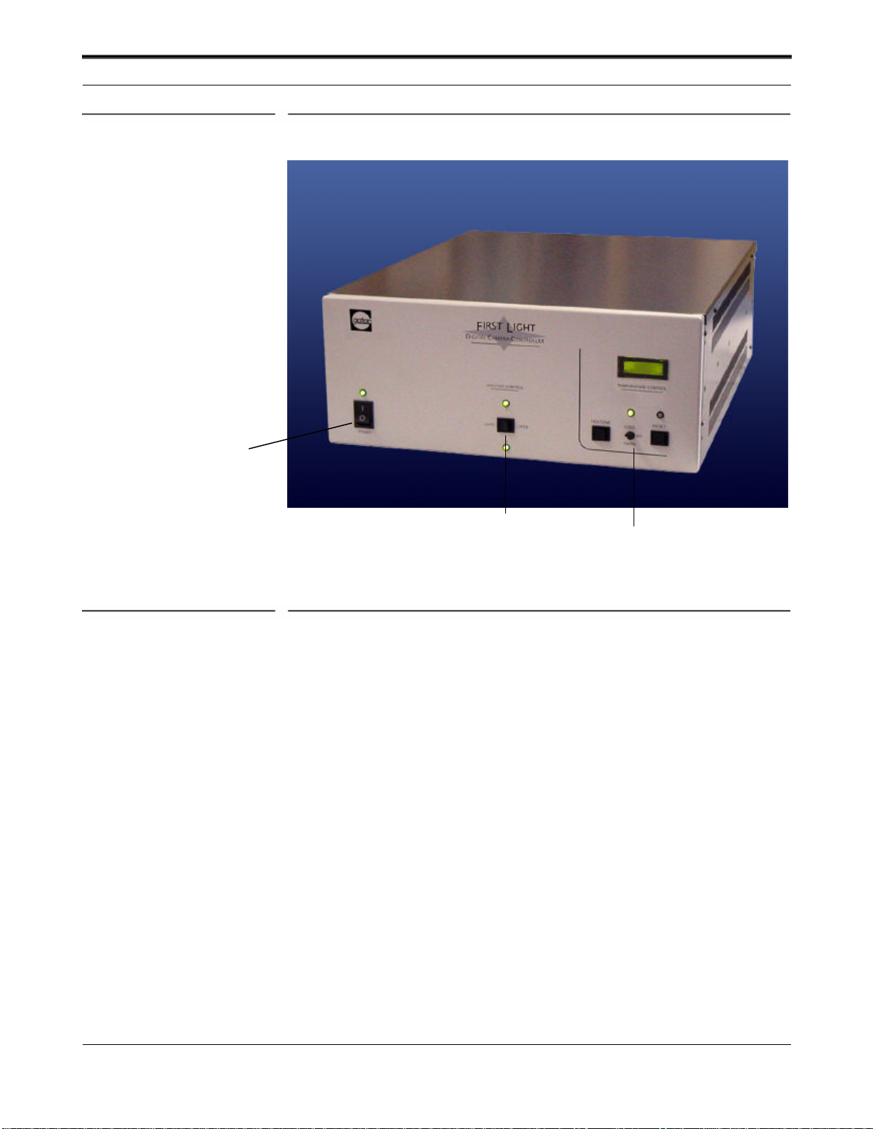
•Switch on the CCD camera controller (Fig. 2-1), the LED will turn
green.
•Flip the Shutter switch to AUTO.
•Flip the Peltier Cooler switch to the COOL position. For best results it
is recommended waiting (2 hours or more) for the system to stabilize.
•Turn the computer on (if it is not on yet) and double click on the
DigitalMicrograph icon to launch the application.
The Workplace
UltraScan User’s Guide Reference Series Rev 1.0 2-2
Figure 2-1Camera controller
2.1 The Workplace
When DigitalMicrograph is launched, you will see the commonly used tools
(left side), the Image Acquisition and Saving tools (right side), and the Result
window as shown in Figure 2-1. These tools are composed by “floating”
windows fully stackable to allow customization.
Power switch
Peltier switch
Shutter switch

Camera Configuration
UltraScan User’s Guide Reference Series Rev 1.0 2-3
Figure 2-2DigitalMicrograph Workplace
2.2 Camera Configuration
If the camera is already configured by a Gatan service engineer, this section can
be ignored.
Before starting acquiring images, it is necessary to configure the camera. This
process is shown in Figure 2-3.
Commonly used tools
Imagedisplay
Image acquisition and saving t
ools
Results window

Set Bias Levels
UltraScan User’s Guide Reference Series Rev 1.0 2-4
Figure 2-3(a) Camera Menu (b) Camera configuration
•Select Configure Camera in the Camera menu (Figure (2-3a).
•In the Camera configuration dialog box (Figure 2-3b), you can change
the name of the camera by typing in the Name field.
•Image rotation can be specified in the Rotation pull-down menu.
•The coordinates for column defect correction are entered in the Defects
field. For example, entering the following:
r0-8, r4088-4095, c0-8,c4088-4095
(r and c indicates row and columns respectively) corrects for the 8
pixels wide edge which does not contain active CCD pixels in the case
of the UltraScan 4000.
•It is important to specify the Primary and Alternate (if there is one set
up) shutter available to the camera.
•Finally you should specify the shutter status, i.e. the state of the shutter
when the CCD camera is not acquiring any images. Shutter Normally
Closed is the default setting.
2.3 Set Bias Levels
In 4-channel CCD readout, the entire CCD sensor is divided into 4 sectors
(called quadrants). It is common that each quadrant has a different bias level.
Set Bias Levels
UltraScan User’s Guide Reference Series Rev 1.0 2-5
This can result in CCD images with visible quadrant (like a chess board
pattern).
Under the Camera menu (Figure 2-3), Set Bias Levels routine automatically
measures and sets the bias for each quadrant. The bias setting is written to the
First Light Controller. This will remove the majority of the image contrast from
quadrant to quadrant in an evenly illuminated flat field image and maximize the
dynamic range.
The Set Bias Levels should be run before the linearization procedure (next
section) and after the camera is cooled. It is not necessary to run Set Bias
Levels again.
When running this routine, it does not matter if the viewing screen is raised or
not since the automatic procedure blanks the beam on the CCD as needed.
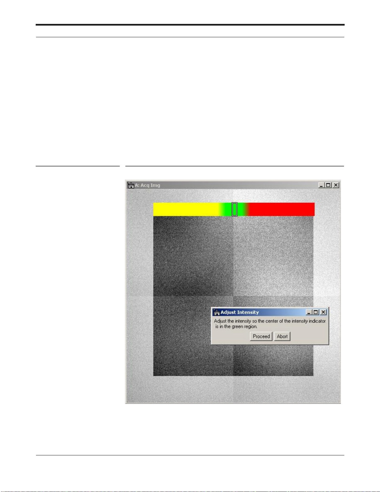
Figure 2-4Set the target intensity

Quadrant Correction Reference
UltraScan User’s Guide Reference Series Rev 1.0 2-6
2.4 Quadrant Correction Reference
The above Set Bias Levels routine removes gross contrast variation from
quadrant to quadrant. The remaining variation can be removed by the Prepare
Quadrant Correction Reference routine.
Before running the Prepare Quadrant Correction Reference routine, make
sure the CCD has reached its stable temperature (reading from the front panel
of the First Light controller).
Remove the sample from the field of view and spread the illumination evenly
across the CCD sensor (similar to “prepare gain reference” image).
Under Camera menu (Figure 2-3a), run the Prepare Quadrant Correction
Reference routine. Set the target intensity so the center of the intensity
indicator is in the green region (Figure 2-4). Follow the instructions on the
screen. This is a time consuming procedure as images with various exposures
are recorded to cover full intensity range. It typically takes about 50 and 75
minutes for US1000 (2k x 2k) and US4000 (4k x 4k) respectively. Once the
procedure completes, a reference image is stored in DigitalMicrograph
“Reference Images” folder for later use.
Typically it is not required to run this routine frequently.
It is important to run Gain normalization routine (next section) after Prepare
Quadrant Correction Reference in order to activate the linearization
correction routine, so that it is applied to all the future acquired images.
2.5 Gain Normalization
It is important to prepare a new gain reference image after the CCD has reached
the equilibrium temperature (normally this takes about 1-2 hours). The gain
reference image should be checked regularly.
To prepare gain reference image, remove specimen from the field of view,
evenly spread the illumination across the CCD sensor.
Under the Camera menu (Figure 2-3), choose Prepare Gain Reference. Set
the target intensity to the value of 10,000-20,000 (for US4000,it may be
necessary to set the target intensity close to 10,000 counts since the CCD may
saturate around 20,000 counts. See the “Most Often Asked Questions”in
section 5 for details). Normally it is sufficient to set the frames to average to 4.
Then simply follow the instructions on the screen.
It is recommended to perform this operation when
•The camera temperature is stable (check the temperature display on the
controller front panel),
•Every time the camera is switched on,

Magnification Calibration
UltraScan User’s Guide Reference Series Rev 1.0 2-7
•Once a week if the camera is always on, or
•Before acquiring any important images.
2.6 Magnification Calibration
The displayed nominal magnification on TEM is for photographic film and has
an accuracy of 5-10%. The CCD camera is located on a different plane (height
wise) respect to the film camera. As a consequence, the magnification must be
calibrated. The calibration is done using Reference calibration samples.
At “Low” magnifications:
•Use “cross grating sample” or any sample having known spacing
At “High” magnifications:
•Use “graphite” or any crystalline samples having known lattice spacing
•Use the FFT method.
It is very important to make sure DigitalMicrograph software correctly reads
the TEM magnification. If the communication between the computer and the
TEM is established, the magnification is read automatically. Otherwise, please
make sure DigitalMicrograph is set to prompt the user to enter a value for TEM
magnification every time an image is to be acquired. This can be set by
choosing the “Global Microscope Info” window shown in Figure 2-5under the
Microscope menu (Figure 2-6).

Magnification Calibration
UltraScan User’s Guide Reference Series Rev 1.0 2-8
Figure 2-5Global Microscope Infowindow
Figure 2-6Microscope menu
In the “Magnification” section in the “Global Microscope Info” window
(Figure 2-4) choose:
•Source from: User
•Ask User: Always
•Click OK
2.6.1 Low magnification
•Record an image of a cross grating sample (Figure 2-7)

Magnification Calibration
UltraScan User’s Guide Reference Series Rev 1.0 2-9
Figure 2-7Cross grating sample
•Choose “Calibrate image…” under the “Microscope” menu (Figure 2-
6).
Follow the on screen instructions (Figure 2-8)
Figure 2-8Instructions window
A red line will appear on the image.
•Position it on a feature of known size.
•Press OK on the “Calibrate image” window.
•Enter the correct distance for the selected feature (for example 10 line
pairs of cross grating sample where the distance = 10 x 0.463µm) in the
“Calibration” window and select the units (see Figure 2-9).

Magnification Calibration
UltraScan User’s Guide Reference Series Rev 1.0 2-10
Figure 2-9Calibration window
•Press OK.
•Choose YES in the next window (see Figure 2-9) to complete the
magnification calibration.
Figure 2-10 Choose YES to complete the calibration
The calibration can be checked on the calibration table containing pairs of
value: the nominal microscope magnification and the calibrated value. To view
the magnification table:
•Select “Magnification table” (Figure 2-11) from the “Microscope”
menu (Figure 2-6).

Magnification Calibration
UltraScan User’s Guide Reference Series Rev 1.0 2-11
Figure 2-11 Magnification table
The first column represents the nominal TEM magnification and the second
column is the actual magnification at the CCD.
2.6.2 “High” magnification
•Record a lattice image of the crystalline sample (Figure 2-12).
Figure 2-12 High-resolutionimage of a crystalline sample
•Choose “Calibrate image from Diffractogram…” under the
“Microscope” menu (Figure 2-6).

Magnification Calibration
UltraScan User’s Guide Reference Series Rev 1.0 2-12
A diffractogram will be calculated (Figure 2-13).
Figure 2-13 Diffractogram
•Follow the on screen instructions (Figure 2-14)
A red line will appear on the diffractogram.
•Position the endpoints of the red line on two symmetrical diffraction
peaks (Figure 2-13).
•Press OK to specify the reciprocal unit and the d-spacing (in the
corresponding real units) in the next window (Figure 2-15).
Figure 2-14 High magnification calibration instructions
This manual suits for next models
1
Table of contents
Other Gatan Digital Camera manuals

Popular Digital Camera manuals by other brands


Kogan
Kogan SMARTERHOME 2S user guide

Konica Minolta
Konica Minolta DiMAGE Z6 user manual

Tritech
Tritech MD4000 Operator's & installation manual

Kodak
Kodak P712 - Easyshare 7.1MP Digital Camera user guide

Allied Vision
Allied Vision Prosilica GT Series Technical manual

Mini Gadgets
Mini Gadgets VRCLIP8GB quick start guide


