Gates Radio Company Stereo Statesman Console M-6540C User manual
•
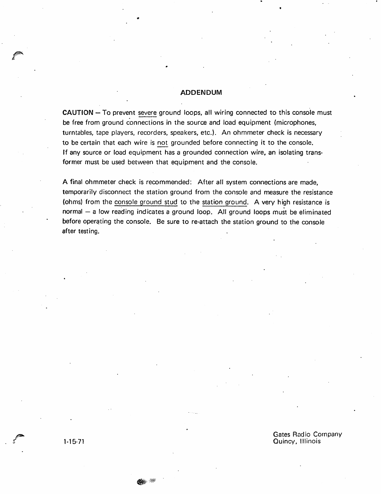
ADDENDUM
CAUTION -To prevent
severe
ground loops, all wiring connected
to
this console must
be
free from ground c'onnections in
the
source and load equipment (microphones,
turntables, tape players, recorders, speakers, etc.).
An
ohmmeter check
is
necessary
to
be
certain
that
each
wire
is
not
grounded before connecting
it
to
the console.
If
any source
or
load equipment
has
a grounded connection wire, an isolating trans-
former must
be
used
between
that
equipment and the console.
A final ohmmeter check
is
recommended:
After
all system connections are made,
temporarily disconnect the station ground
from
the console and measure the resistance
(ohms) from the console ground stud
to
the
station ground. A very high resistance
is
. .
normal - a low reading indicates a ground loop.
All
ground loops must
be
eliminated
before operqting the console.
Be
sure
to
re-attach the station ground
to
the console
after testing.
1-15·
71
Gates Rudio Cornpany
Quincy, Illinois
..
:
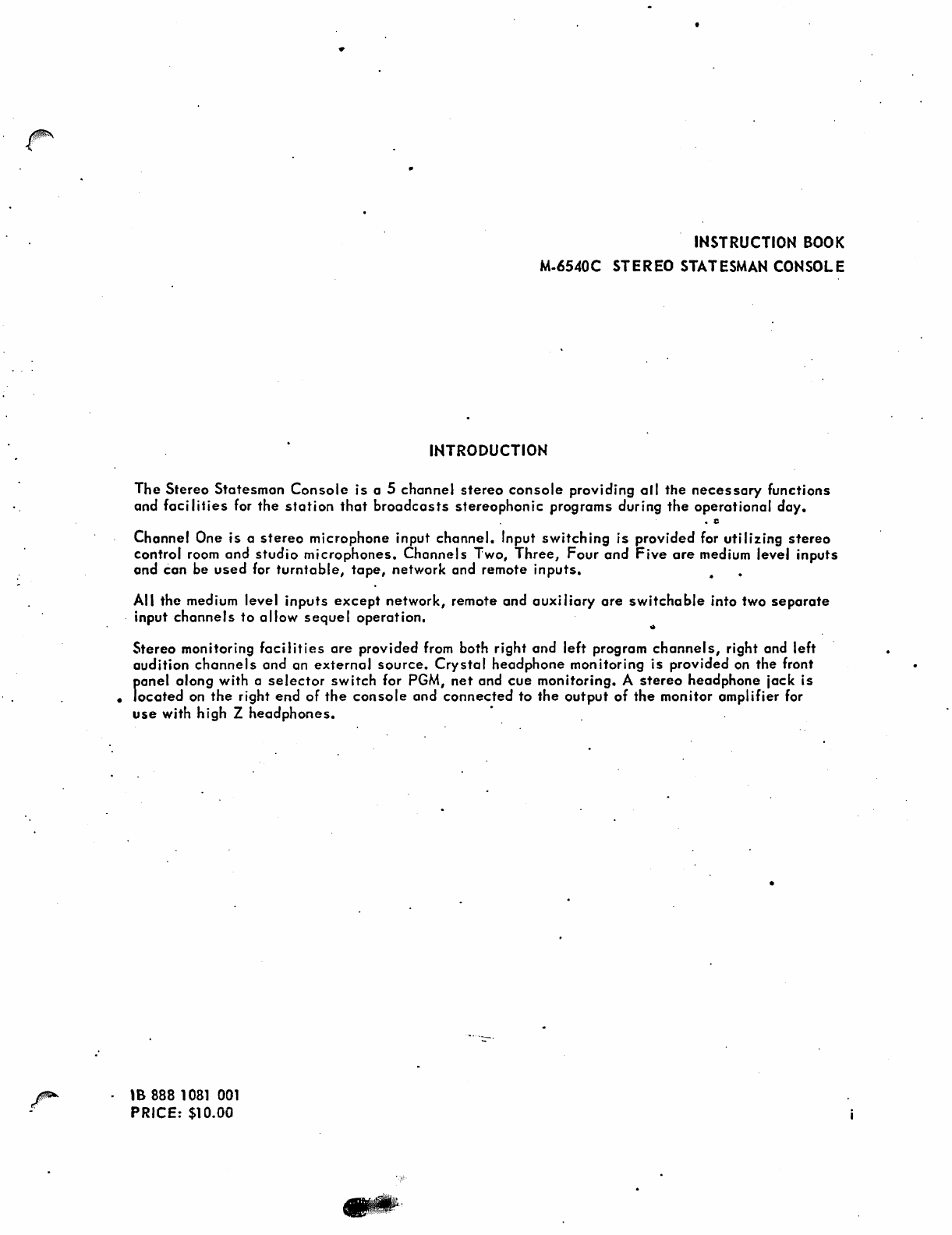
INSTRUCTION
BOOK
M.6540C STEREO STATESMAN CONSOLE
INTRODUCTION
The
Stereo
Statesman
Console
is
a 5
channel
stereo
console
providing
all
the
necessary
functions
and
facilities
for
the
station
that
broadcasts
stereophonic
programs
during
the
operational
day
•
Channel
One
is
a
stereo
microphone
input
channel.
Input
switching
is
provided
for
utilizing
stereo
control room
and
studio
microphones.
Channels
Two,
Three,
Four
and
Five
are
medium level
inputs
and
can
be
used
for
turntable,
tape,
network
and remote
inputs.
• •
All
the
medium
level
inputs
except
network,
remote
and
auxiliary
are
switchable
into two
separate
. input
channels
to
allow
sequel
operation.
Stereo
monitoring
facilities
are
provided
from both
right
and
left
program
channels,
right and left
audition
channels
and
an
externol
source.
Crystal
headphone
monitoring
is
provided
on
the
front
panel
along
with
a
selector
switch
for PGM,
net
and
cue
monitoring.
A
stereo
headphone
jack
is
•
located
on
the
right
end
of
the
console
and
connected
to
the
output
of
the
monitor
amplifier
for
use
with
high
Z
headphones.
.
.
'8
888
1081
001
PRICE: $10.00
•
SECTION
1.
2.
3.
4.
5.
TABL E OF CONTENTS
INTRODUCTION
TABLE
OF
CONTENTS
SPECIFICATIONS
INSTALLATION
2.1
Unpacking Instructions
2.2 Audio System
Installation
Information
2.3
Installation
Procedure
a. Power Connections
b.
Warning
Lights
c. Input Connections to Console
d. Output Connections to.Console
OPERATION
3.1
Channel Balance
3.2 Cue System
MAINTENANCE
Table 1
PARTS
LIST
DIAGRAMS -
*Loss
Pad Chart
*Speaker Matching Transformer Information
827 3822
001
M6549C Preamplifier.
827
3823
001
M6550C Booster
Amplifier
827 4088
001
M6550C Output
Amplifier
827 3890
001
M6551A 30V. Regulated Power Supply
827
2385
001
M6552 43V. Power Supply
838
2669
001
Cable
Inlet
& Mounting Diagram
842 5348
001
Functional
Diagram
842 6207
001
Wiring Diagram
852 6262
001
Installation
Diagram
PAGE
ii
1-1
2-1
2-1
2-1
2-1
2-1
2-2
2-2
2-2
3-1
3-1
3Tl
4-1
4-3
5-1
ii
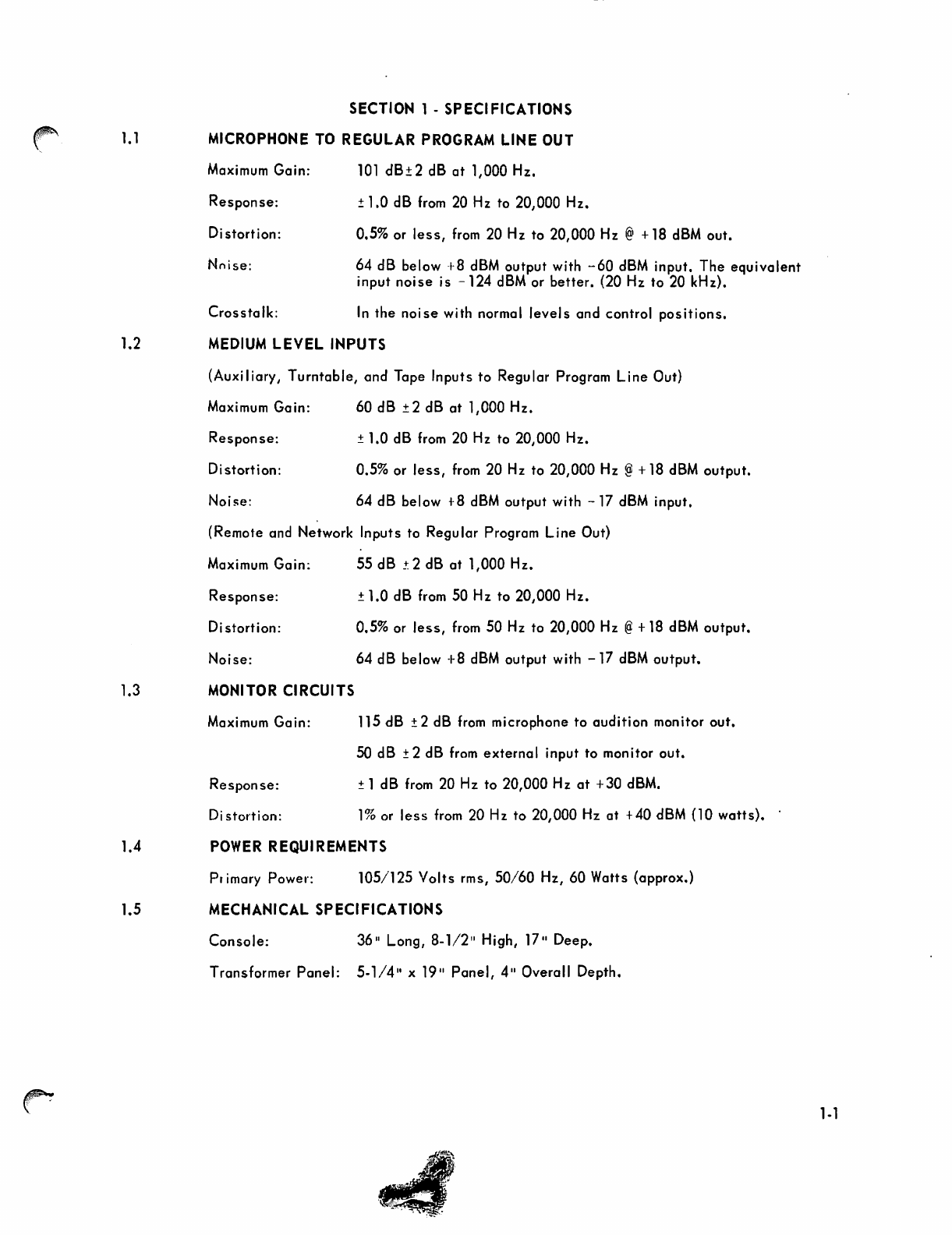
1.1
SECTION 1 - SPECIFICATIONS
MICROPHONE
TO
REGULAR PROGRAM
LINE
OUT
Maximum
Gain:
Response:
Distortion:
Nnise:
Crosstalk:
1
Old
B±2
dB
at
1,
000
Hz.
±1.0
dB
from
20
Hz
to
20,000
Hz.
0.5%
or
less,
from
20
Hz
to
20,000
Hz
@+18 dBM
out.
64
dB
below
+8 dBM
output
with
-60
dBM
input.
The
equivalent
input
noise
is
-124
dBM
or
better.
(20
Hz
to
20
kHz).
In
the
noi
se
wi
th
normal
level
s
and
control
pos
itions.
1.2 MEDIUM
LEVEL
INPUTS
(Auxi I
iary
I
Turntable,
and
Tape
Inputs
to
Regu
lar
Program
Line
Out)
Maximum
Gain:
Response:
Di
stortion:
Noise:
60
dB
±2
dB
at
1,
000
Hz.
± 1.0
dB
from
20
Hz
to
20,000
Hz.
0.5%
or
less,
from
20
Hz
to
20,000
Hz
@+
18
dBM
output.
64
dB
below
+8 dBM
output
with
-
17
dBM
input.
(Remote
and
Network
Inputs
to
Regular
Program
Line
Out)
Maximum
Gain:
Response:
Di
stortion:
Noise:
1.3
MONITOR CIRCUITS
Maximum
Gain:
Response:
Di
stortion:
55
dB
!:2
dB
at
1,000
Hz.
±1.0
dB
from
50
Hz
to
20,000
Hz.
0.5%
or
less,
from
50
Hz
to
20,000 Hz @+18 dBM
output.
64
dB
below
+8
dBM
output
with
-17
dBM
output.
115
dB
±2
dB
from
microphone
to
audition
monitor
out.
50
dB
±2
dB
from
external
input
to
monitor
out.
±1
dB
from
20
Hz
to
20,000
Hz
at
+30 dBM.
1% or
less
from
20
Hz
to
20,000 Hz
at
+
40
dBM
(l0
watts).
1.4
POWER
REQUIREMENTS
Pr
imary
Power:
105/125
Volts
rms,
50/60
Hz,
60
Watts
(approx.)
1.5 MECHANICAL SPECIFICATIONS
Console:
Transformer
Panel:
36"
Long,
8-1/2"
High,
1711
Deep.
5-1/4"
x
19
11
Panet
411
Overall
Depth.
."
..
\IIC\
of!
~.
,
.....
~
..•
1-1

2.1
SECTION
2 .
INSTALLATION
UNPACKING
INSTRUCTIONS
The
console
is
shipped
in
several
boxes
or
cartons.
The
following
main
items
will
be
enclosed.
1.
Stereo
Statesman
Conso
Ie
with
all
amplifiers
installed.
2.
Transformer
Panel.
3.
Decal
Kit.
4.
Stick-on
Label
s.
5.
Instruction
Book.
6.
Six
Speaker
Transformers.
The
sh
ipping
con
to
iner
should
be
unpacked
carefu
lly
and
inspected
for shipping
damage.
If
damage
is
found,
contact
the
shipper
immediately.
After
he
has
approved
the
damage
report,
wh
ich indi
cates
he
wi
II
accept
your
bi"
ing for
the
damage,
or~er
new
parts
from
Gates
Radio
Company. Our
billing
of
these
parts
plus
transportation
expense
will
be
your
claim
to
the
Transportation
Company.
The
Stereo
Statesman
Console
is
covered
under
the
Standard
Gates
Warranty,
which
is found on
the
bock
of
the
front
cover.
2.2
AUDIO
SYSTEM
INSTALLATION
INFORMATION
Before
any
actual
installation
is
started,
the
following
points
should
be
studied
care-
fu
Ily,
physical
location
of
all
components
shou
Id
be
decided
and
cable
routing
should
be
determined.
Only
after
these
plans
have
been
completed,
may
installation
be
made
in
an
orderly
manner.
The
transformer
panel
is
5.1/4" x
19"
and
can
be
rock
mounted.
If
desired,
it
may
be
mounted in a
small
wall
box or
under
the
base
of a
desk.
Ample
ventilation
must
be
provided
since
the
unit
generates
some
heat.
When
rack
mounted,
the
panel
is
designed
for
natural
convection
cooling.
If
the
ambient
temperature
of the
rack
is
below 50°C.
(122°F.)
the
rock
does
not
need
forced
air
ventilation.
Cable
routing
of
external
connections
of
various
signal
levels
is
of
prime
importance.
The
low
level
microphone
input
cables
should
be
cabled
separate
from all
the
other
level
cables.
If
it
is
necessary
to
use
cables
of
different
levels
in a common
conduit,
the
difference
between
the
lowest
and
the
highest
level
in
the
two
cables
should
not be
greater
than
40
dB.
Phys
ica
I
isolation
is
the
best
way to
avoid
trouble
between
paralIel
cables.
Six
inches
or more
spacing
is
preferred.
The
console
grounding
system
is
based
on
the
one
point
ground.
Different
circuit
grounds
are
insulated
from
the
chassis
and
go
directly
to
the
ground
stud
located
at
the
right
end
of
the
cabinet.
Connect
the
station
ground
to
the
cabinet
ground
stud.
External
grounds
connected
to
circuit
grounds
in
the
console
will
destroy
this
system.
A
shield
ground
bus
in
provided
by
the
side
of
each
of
the
input
and
output
terminal
blocks
of
the
console.
All incoming
and
outgoing
shields
must
be
connected
to
these
busses.
2.3
INSTALLATION
PROCEDURE
a.
Power
Connections
See
installation
drawing
at
rear
of
this
book.
2·1
The
output
line
cables
from
this
console
are
medium
level
and
should
be
routed
carefully
to
prevent
crosstalk
back
into
low
level
input
circuits.
Again,
observe
corre~t
phase
relationship
between
output
lines
to
insure
proper
sound
perspective
between
the
left
and
right
channels.
All
speaker
wiring
is
high
level
and
must
be
run in
separate
conduit
away
from
low level program
circuits.
Stereo
monitoring
is
provided for
all
studios
as
well
as
external
lobby
speakers.
45
to
16/8/4
Ohm
speaker
matching
transformers
are
supplied
for matching 16,
8,
or 4 Ohm
speakers
to
the
output
of
the
monitor
~.
amplifier.
Speaker
connections
are
shown
in
the
Installation
Drawing.
CAUTION·
GROUNDING
NOT
E:
To
prevent
severe
ground loops,
all
wiring connect-
ed
to
this
console
mu
st
be
free
from
ground
connec-
tions
in
the
source
and
load
equipment (micro-
phones, turntables, tape
players,
records,
speakers,
etc.).
An ohmmeter
check
is
necess9ry'
to
b~
certain
that
each wire
is
not grounded before connecting
it to the
console.
If
any
source
or
load equipment
has
a grounded
connection
wire,
an
isolating
trans-
former
must
be
used
between
that
equipment and the
console.
..
A final ohmmeter
check
is
recommended: After
all
system
connections
are made, temporarily discon-
nect
the
station
ground
from
the
console
and meas-
ure
the
resistance
(ohms)
from
the
console
ground
stud
to
the
station
ground. A
very
high
resistance
is
normal -a low reading
indicates
a ground loop.
All
ground loops
must
be
eliminated
before
operat-
ing the
console.
Be
.sure
to re-attach the station
ground to
the
console
after
testing.
2~
~
"
"I

~-.
SECTION
3 •
OP
ERATION
On
the upper front
pane
I,
above
the
five
channel
mixers
are
switches
that
perform input
switching
function for
each
channel.
The
selector
switch
on
the
extreme
left
is
used
to
swi tch
between
stereo
microphones
in
the
control
room and
studio.
Lever
keys
are
located
above
each
of
the
input
channel
mixers.
With
the
Channel
#1
lever
key
in
the
right
position,
the
microphone
preamplifiers
feed
the
left
and right program
busses.
These
same
microphones
will
be
switched
to
the
left
and
right
audition
busses
when
the
mixer key
is
placed
to
the
left.
The
switch
to
the
upper
left
of
Channel
#2
is
used
to
switch
the
auxi Iiary input into thi
schanne
I.
The
pairs
of
switches
located
above and
between
the
channel
mixers
#2
and #3,
#3
and #4,
and
#4
and
#5
are
switchable
into
these
channels.
The
pair
of
switches
above
and
to
the
right
of
the
Channel
#5
mixer
is
used
for
switching
the
remote
and
network
lines
into
Channel
US.
When
in
the
left
position,
the
remote
switch
provides
pre-hear
and
cueing
faci I
ities.
In
the
center
pos
ition,
the
inputs
are
term
inated.
When
in
the
right
position,
the
remote
line
feeds
the
cue
am-'plifier for
pre-hear
cueing.
The
pre-
hear
cueing
is
also
available
on
the
network
input
switch.
The
head
phones
can
also
be
used
to
I.isten
to
the
network when
the
phone
selector
is
switched
to
the
net
position.
The
monitor input
selector
is
located
on
the
right lower
section
of
the
panel.
Input
switching
allows
stereo
monitoring
of
the
audition
busses,
the
program
output
lines,
and
an
external
signal
source.
The
gain
of both
the
"Ieft"and
IIright
II
monitor ampl
ifiers
is
controlled
by
the
dual
gain
control
located
just
below
the
monitor input
selector.
The
gain
control
s for
the
left
and
right program
channel
s
are
located
on
the
lower
right
section
of
the
panel.
3.
1
3.2
CHANNEL
BALANCE
Once
the
gain
of
the
left
program
channel
has
been
adjusted
to
the
desired
level,
the
inter-channel
(left-right)
balance
can
be
set
by
switching
the
channel'
balance
switch
to
the
"null
II
position.
This
switch
is
located
on
the
meter pad printed
cir-
cuit
board
fastened
to
the
back
of
the
VU
meters.
With
the
switch
in
the
"null"
position,
the
left
channel
VU
meter
is
connected
between
the
FM
left
and
FM
right
e.rogram
channels,
and
thus
reads
the
difference
in
signal
levels
between
channels.
Feed
a monophonic
recording
into
the
stereo
medium
level
channel
and
adjust
the
level
of
the
FM
right
program
gain
control
until
the
VU
meter
"nulls".
This
indicates
that
the
program I
ines
are
balanced
within
±
0.5
dB.
After
the
balancing
procedure
is
completed,
the
switch
should
be
returned
to
the
lIoperate
ll
position.
CUE
SYSTEM
The
cue
amplifier
is
used
to
pre-hear
the
remote
and
network
lines
and for
cueing
of
the
medium
level
inputs
such
as,
turntable,
tape,
etc.
The
gain
control
is
located
between
Channel
#1
and
Channel
#2
mixer.
The
cue
speaker
on
the
console
is
set
up
to
be
muted when
the
control
room
microphones
are
turned
on,
however,
this
muting
does
not
disable
the
cue
position
on
the
phone
selector
switch,
so
it
is
possible
to
cue
a
record
by monitoring
the
cue
circuit
with
headphones.
The
muting
has
been
pre-assigned
for
the
control
room
and
studio
speakers.
Muting
is
accomplished
by
the
two
relays
mounted on
the
amplifier
chassis
and
is
selected
by
microphone
input
switch.
3-1

4.1
SECTION
4 - MAINTENANCE
TROUBLESHOOTING
When
troubleshooting,
it wi
II
be
necessary
to
make
voltage
measurements.
These
are
given
on
the
schematic
diagrams
of
the
various
amplifiers.
It
is
recommended
that,
after
the
console
is
insta
lied
and
operating
sati
sfactori
Iy,
these
readings
shou
Id
be
checked
and
recorded
on
the
schematic.
This
wi
II
provide
the
station
engineer
with 0
record
of
the
actual
voltage
readings
in
his
installation,
using
his
meter.
If
trouble
later
developes,
he
will
then
be
better
able
to judge
whether
or
not
a porticulor c ir-
cuit
is
operating
properly
since
he
wiil
have
available
a
record
of
the
various
readings
of
his
particular
equipment.
DC
readings
were
taken
with a
20,000
ohm/voltmeter
as
indi
cated
on
the
schematic.
RMS
signal
voltages
are
shown
in
parenthesi
s and
must
be
measured
with a vacuum
tube
voltmeter.
If a VTVM
is
used
to
measure
DC
voltages,
slightly
higher
readings
may be
obtained.
TROUBLESHOOTING GUIDE
1.
No
indication
on
either
or both of
the
VU
meters
and
the
monitors
onIy
operate
from
the
audition
channel
and
the
external
input.
a.
Interchange
the
program ampl
ifiers
with monitor ampl
ifiers.
b.
Check
for 30
volts
between
terminal
s
#3
and
#5
of
the
booster
board and
ter-
minaIs
#3
and
119
of
the
output
boar~.
2. No
signal
on
either
or
both of
the
program
output
lines,
but
indication
on
the
VU
meters.
a.
Check
external
cable
connections
on
TB2.
b.
Check
S18 and
output
pad
board.
3.
No
signal
can
be
heard
from any of
the
nlon itor
speakers
but
the
program
channe
Is
operate
O.K.
a.
Interchange
the
monitor
amplifiers
with
the
program
amplifiers.
b.
Check
for
30
volts
between
terminals
113
and
115
of
the
booster
board
and
43
volts
between
terminal
s
n3
and
1t9
of
the
output
board.
4.
No
signal
can
be
heard
from
the
cue
speaker.
a.
Interchange
the
cue
amplifier
with
either
the
program
or
monitor
amplifier.
b.
Check
for
30
volts
between
terminal
s
#3
and
#5
of
the
booster
board
and
ter-
minals
#3
and
ii9
of
the
output
board.
c.
Check
cue
speaker.
5.
No indi
cation
can
be
seen
on
VU
meter
when
talking
into
the
control
room or
studio
microphones,
but
the
medium
level
channels
operate
O.K.
a.
Interchange
preamplifiers
if on
Iy
one
channel
shows
no
indication.
b.
Check
for
30
volts
between
terminal
s
#7
and
118.
c.
Check
contacts
on
switch
S1.
6.
No
indication
can
be
seen
on
the
VU
meter
when
feeding
one
of medium
level
inputs.
a.
Check
the
input
switch,
the
channel
mixer, and
program/audition
lever
key.
4-1
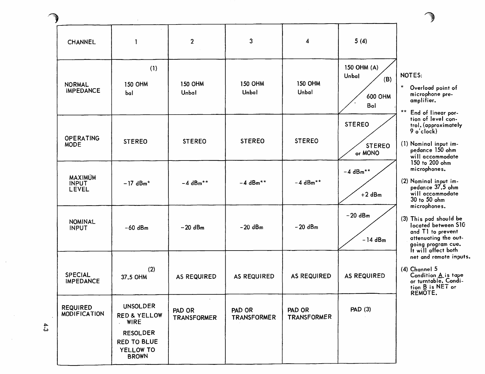
CHANNEL 1 2
(1)
NORMAL
ISO
OHM
150
OHM
IMPEDANCE
bal
Unbal
OPERATING
STEREO
STEREO
MODE
MAXIMOM
INPUT
-17
dBm*
-4
dBm**
LEVEL
NOMINAL
INPUT
-60
dBm
-20
dBm
SPECIAL
(2)
IMPEDANCE
37.5
OHM
AS
REQUIRED
REQUIRED
UNSOLDER
PAD
OR
MODIFICATION
RED
& YELLOW
TRANSFORMER
WIRE
RESOLDER
RED
TO
BLUE
YELLOW
TO
BROWN
3 4
150
OHM
150
OHM
Unbal
Unbal
STEREO
STEREO
-4
dBm**
-4
dBm**
-20
dBm
-20
dBm
AS
REQUIRED
AS
REQUIRED
PAD
OR
PAD
OR
TRANSFORMER
TRANSFORMER
5
(4)
150
OHM
(A)
Unbal
(B)
600
OHM
Sal
STEREO
STEREO
or
MONO
-4
dBm**
+2
dBm
-20
dBm
-14
dBm
AS
REQUIRED
PAD
(3)
NOTES:
* Overload point
of
microphone
pre-
amplifier.
**
End
of linear
por-
tion of level
con-
trol. (approximately
9
0'
clock)
(1) Nominal input
im-
p~dance
1
SO
ohm
wi
II
accommodate
1
SO
to
200
ohm
microphones.
(2)
Nominal i'!Put
im-
pedance
37.5
ohm
wi
II
accommodate
30
to
SO
ohm
microphones.
(3)
This
pad
should
be
located
between
S
10
and
T1
to
prevent
attenuating the out-
going
program
cue.
It
wi
II affect
both
net
and
remote
inputs.
(4)
Channel
5
Condition A is t'lpe
or
turntable. Condi-
tion B is NET
or
REMOTE.
~
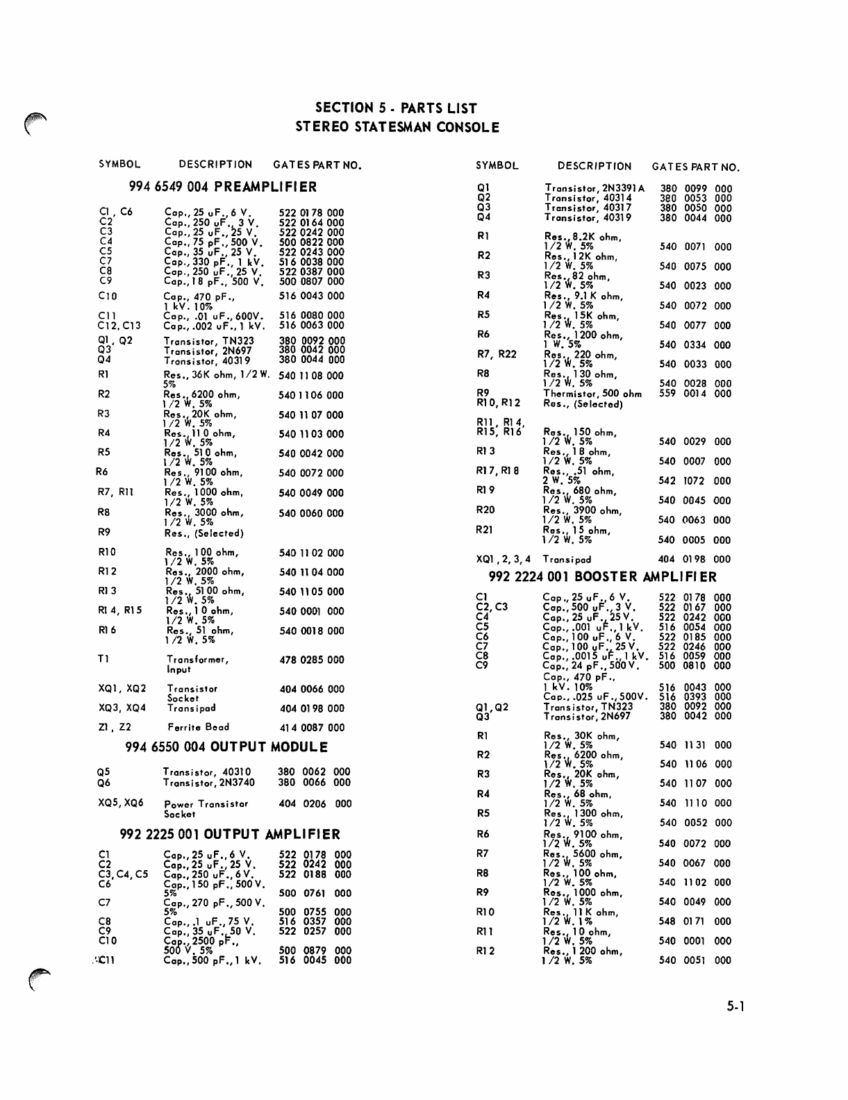
SECTION
5 •
PARTS
LIST
STEREO
STATESMAN
CONSOLE
SYMBOL
DESCRIPTION
GA
T
ES
PART NO.
SYMBOL
DESCRIPTION
GAT
ES
PART NO.
9946549
004
PREAMPLI
FI
ER
Ql
Transistor,2N3391A
380 0099 000
Q2
T
ransi
stor,
40314 380 0053 000
Cl,
C6
Cop.,25
uF.,
6 V. 522 0178 000 Q3
Transistor,
40317 380 0050 000
C2
Cap.,
250
uF'
2
3 V. 522
0164000
Q4
Trans
i
stor,
4031
9 380 0044 000
C3
Cap.,25
uF.,
5
V.
5220242000
Rl
Res.,8.2K
ohm,
C4
Cap.,
75
pF.,
500 V.
5000822000
1/2
W.
5%
540
0071
000
C5
Cap.,
35
uF.,
25
V.
5220243000
R2
Res.,
12K ohm,
C7
Cap.,
330
pF.,
1 kV.
5160038000
1/2
W.
5%
540 0075 000
C8
Cop., 250
uF.,
25
V.
5220387000
R3
Res'
W
82 ohm,
C9 Cap., 18
pF.,
500
V.
5000807
000
1/2
.5%
540 0023 000
Cl0
Cap.,
470
pF.,
516
0043 000
R4
Res.,
9.1
K ohm,
1 kV.
10%
112
W.
5%
540 0072 000
Cl1 Cop.,
.01
uF.,600V.
516
0080000
R5
Res W15K ohm,
C12, C13
Cop.,
.002
uF.,
1 kV. 516 0063 000
1/2
.5%
540 0077 000
Ql,
Q2
Transistor,
TN323 380
0092000
R6
Res.,
1200 ohm,
1 W.5% 540 0334 000
Q3
Transistor,
2N697 380 0042 000 R7, R22 Res.W
220 ohm,
04
Tronsistor,40319
380 0044 000
1/2
.5%
540 0033 000
Rl
Res.,
36K
ohm, 112
W.
5401108000
R8
Res.
W
130 ohm,
5%
1/2
•
5%
540 0028 000
R2
Res'
W
6200 ohm,
5401106
000
R9
Thermistor,500
ohm
559 0014 000
112
.5%
RIO, R12
Res.,
(Selected)
R3
Res.,
20K
ohm,
5401107
000
1/2
W.
5%
Rll,
R14,
Res.
W
150 ohm,
R4
Res'
W
ll
0 ohm, 540
1103000
R15, R16
1/2
.5%
1/2
.5%
540 0029 000
R5
Res.,
510 ohm,
5400042000
R13
Res.,
1B ohm,
1/2
W.
5%
1/2
W.
5%
540 0007 000
R6
Res.,
9100 ohm, 540 0072 000 R17,
RIB
Res.,
.51
ohm,
1/2
W.
5%
2
W.
5%
542 1072 000
R7, Rll
Res.,
1000 ohm,
5400049000
R19
Res.
W
680 ohm,
1/2
W.
5%
1/2
.5%
540 0045 000
R8
Res.,
3000 ohm,
5400060000
R20
Res.,
3900 ohm,
1/2
W.
5%
1/2
W.
5%
540 0063 000
R9
Res.,
(Selected)
R21
Res.,
15
ohm,
1/2
W.
5%
540 0005 000
RIO
Res.,
100 ohm,
1/2
W.
5%
5401102
000
XQl
,2,3,4
Transipod
404 0198 000
R12
Res.,
2000 ohm, 540
11
04000
992
2224001
BOOSTER
AMPLIFI
ER
I/2W.5%
R13
Res.
W
5100 ohm, 540
11
05 000 Cl
Cop.,
25
uF.,
6
V.
522 0178 000
1/2
.5%
Rl
4,
R15
Res.,10
ohm, 5400001 000
C2,C3
Cop.,
500
uF.,
3
V.
522 0167 000
1/2
W.
5%
C4
Cap.,25
uF.
F
25V.
522 0242 000
R16
Res.,
51
ohm,
5400018
000 C5
Cap.,
.001 u
.,1
kV. 516 0054 000
1/2
W.
5%
C6
Cap.,
100
uF.,
6
V.
522 0185 000
C7
Cap.,
100 uF
.~25
V. 522 0246 000
T1
Transformer,
4780285000
C8
Cap.,.0015
u
.,lkV.
516 0059 000
Input C9 C
ap
.,24
pF.,
500V. 500 0810 000
Cap.,
470
pF.,
XQ1,
XQ2
Transistor
4040066
000 1 kV.
10%
516 0043 000
Socket CoP., .025
uF.,
500V• 516 0393 000
XQ3,
XQ4
Trans ipad 404 0198 000
Ql,Q2
Transistor,
TN323 380 0092 000
Q3
Trans
i
stor,
2N697 380 0042 000
ZI,
Z2
Ferrite
Bead 414 0087 000
Rl
Res.,
30K
ohm,
9946550
004
OUTPUT
MODULE
1/2
W.
5%
540
1131
000
R2
Res.
W
6200 ohm,
Transistor,
40310 380 0062 000
1/2
.5%
540
11
06 000
Q5
R3
Res"
20K
ohm,
Q6
Transistor,2N3740
380 0066 000
1/2
W.
5%
540
11
07 000
R4
Res.,
68 ohm,
XQ5,
XQ6
Power
Trans
isf
or
404 0206 000
1/2
W.
5%
540 1110 000
Socket
R5
Res.,
1300 ohm,
1/2
W.
5%
540 0052 000
992
2225001 OUTPUT AMPLIFIER
R6
ReSiN
9100 ohm,
1/2
.5%
540 0072 000
Cl
Cap.,25
uF.,6
V.
522 0178 000
R7
Res.
W
5600 ohm,
C2
Cap.,25
uF.,
25
V.
522
0242 000 112
.5%
540 0067 000
C3, C4, C5
Cop"250
uF" 6 V.
522
0188 000
R8
Res.,
100 ohm,
C6
Cap.,
150
pF.,
500
V.
1/2
W.
5%
540
11
02 000
5%
500 0761 000
R9
Res.,
1000 ohm,
C7
Cap.,270
pF.,
500
V.
112
W.
5%
540 0049 000
5%
500 0755 000
RIO
Res.
W
11
K ohm,
C8
Co
p".1
uF.,
75
V.
516 0357 000
1/2
.1%
548
0171
000
C9
Cap.,
35 uF,!=50
V.
522 0257 000
Rll
Res,W
10
ohm,
Cl0
C08·,2500
p
.,
1/2
.5%
540
0001
000
50
V.5%
500 0879 000 R12
Res.,
1 200 ohm,
.'·ell
Cop.,500
pF.,
1 kV. 516 0045 000
1/2
W.
5%
540 0051 000
~
5.'

SYMBOL OESCRI PT
ION
GAT
ES
PART NO. SYMBOL OESCRI PT
ION
GATES
PA
RT
NO.
~
Lamp
Socket
(Meter
Qty.
MIXING BUS·
p.e.
BOARD
Lamp) 406 0366 000 (4)
XK1,
XK2
Relay
Socket
404
0160
000
992
1874
001
XQ1,XQ2 Tron
..
is
tor Soc
ket
404
0263
000 R1, R2, R4,
R5,R7,R8
R
.
TRANSFORMER
PANEL. 9946556
001
RI0,
Rll,
13,
R14, R16, R17,
C1,C2
COO"
.05
uF.,
R19, R20, R22,
R23,R25,R26
60 V.
d.c.
516 0087 000 R28, R29
Res.,
620 ohm,
1/2
W.
5%
540 0044
000
CB1,CB2
Circuit
Breaker,
R3,
R6,R9
R
1 Amp. 125 V. 606 0116 000 R12, R15,
18,
F2,F3,F4
Fuse,
1.0
A.
Visual
R21, R24,
Res.
W
300 ohm,
Indicating
398
0326
000
R27,R30
1/2
.5%
540 0036
000
T2
Power
Transformer
472
0570
000
T5,
T6 Input
Transformer
478 0285 000
T3,
T4 Power Tronsformer
472
0569 000 METER
PAD
ASSEMBLY·
992
2210
001
TBXl Terminal Board 614 0010 000
Rl
R3
XF2, XF3, Rl
t,
Rt
3
Res.
W
2700
ohm, 540
XF4
Fuseholder
402
0103
000
1/2
.5%
0059 000
EQ1,
EQ2
EQUALI
Z·ER
PAD
R2/R\
R9,
Rl
Res.,
2000 ohm,
992
1871
001
112
W.
5%
540
0056 000
R4,
Rl
0
Res.
W
3000 ohm,
Cl
CoO"
.0033
uf.,
112
.5%
540
0060
000
60
V. 508 0077 000 R6,
R8
Res.,
5600
ohm,
54r
0067
C2
Cap.,
3.9
uf., 35 V.
526
0012 000
1/2
W.
5%
000
R7
Res.,
3900 ohm,
Rl
Res.,
2.7K ohm,
1/2
W.
5%
540 0063 000
112
W.
5%
540 0059
000
R14, R15,
R2
Res.,
2000 ohm, R17, R18,
1/2
W.
5%
540
0056 000 R19, R20,
R3
Res.,
10
ohm,
R22,R23
Res.,
100
ohm, 0025
1/2
W.
5%
540
0001 000
1/2
W.
5%
540
000
R4
Res.,
300 ohm, R16,
R21
Res.
W
820 ohm, 540 0047 000
1/2
W.
5%
540
0036 000
1/2
.5%
Slide Switch,
O.P.O.T.
(with
P.C.
terminals)
604 0348
000
5-3

r·
NOTE:
•
The
following
chart
may
be
used
for
H pads
by
halving R1 and
making R101 equal to
half
of
R
1,
and
by
halving
R2
andmaking
Rl02
equal to
half
of
R2.
For
T pads,
simply
short
out
R101
and
R 102 and
use
R 1 and R2 values directly.
LOSS PAD
CHART
INPUT OUTPUT
R10l 'R102
600/600 ohms
liT"
pads
150/1
50
ohms
"T"
pads
'Rl-R2
R3
R1-R2
dB
loss
ohms ohms dB
loss
ohms
2
68
2700 2
18
4
130
1200
·4
36 .
6 200 820 6
"51
8 270 510 8 .
62
10 330 390
10
82
15 430 220 15 . 110
20 470
120
20
120
25 510
68
25 130
600/150 ohms
"T"
pads
R1
R2
R3
dB
loss
ohms ohms ohms
12
(min) 510 6.8 160
15
510
51
110
20
560
100
62
25
560
120
--. 33
R3
ohms
750
330
200
120
100
56
30
16

Speaker matching transformer
information
using Gates 478-0291-000 transformer.
Shown below
are
some typical installations.
(A)
Lobby
speakers, 8
or
16 ohms.
Lobby
Output
TB2
Primary
(B)
48
ohms
Secondary
Muted outputs,
usi
ng
8 and 16 ohms speakers.
Muted
Output
TB2
48
Lobby
Output
TB2
(C)
48
ohms
Amplifier
Loading
The
load impedance
of
the moni-
tor
amplifier
is
8 ohms. Speaker
loads
of
4
to
16 ohms may
be
used. Loading the
amplifier
low-
er
than
4 ohms may damage the
unit.
Some
suggested
loads are
Iisted below.
1.
One 8 ohms speaker.
2.
Two
16 ohms speakers con-
nected in parallel.
3.
From
one
to
six speakers
using Gates 478-0291-000
speaker matching transform-
ers.
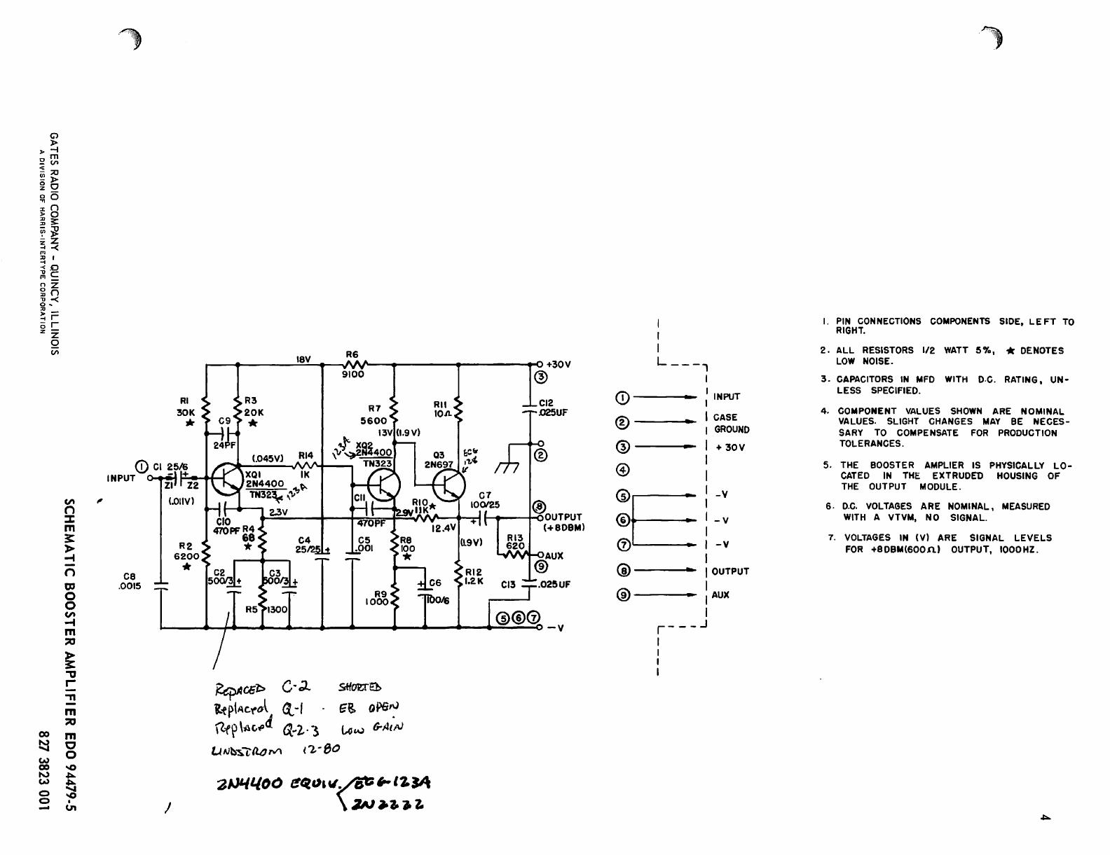
CAUTION:
It
is
extremely important to
the proper operation
of
this
console that the external wir-
ing between TB2 and the
speaker/matching transformer
not
begrounded.

-20
DBM
en
n
:::J:
m
~
>-
-I
0
"'U
:;;0
m
>-
~
."
en
0
!:
c
en
-I
>-
-I
co m
~
n
" 0
w Z
co
'"
~
0
~
.-
<:)
m
9
'"
RI·
36K
*
C9
19.4
V
R3
20K
*'
(.021)
ell
.OIMF
·092MF
...
20DBM
.~
NOTES:
1.
PIN
CONNECTIOMS
COMPONENTS
SIDE.
LEFT
TO
RIGHT.
2.
ALL
RESISTORS
1/2
IATT
5'
3.
CAPACITORS
IN
uF
11TH
D.C.
RATING,
UNLESS
SPECIFIED.
4.
*DENOTES
LOI
NOISE
RESISTORS.
5.
R9
SELECTED
fOR
TOTAL
AIPLIFIER
CURRENT
TO
BE
10-18
IA
(NO
SIGNAL).
PARTS
REPLACEMENT
lAY
REQUIRE
CHANGE
Of
R9
VALUE.
6.
D.C.
VOLTAGES
ARE
NOIINAL.
MEASURED
11TH
A
VTV.,
NO
SIGNAL.
7.
VOlrA~ES
IN
(Y)
ARE
SIGNAL
lEVELS
FOR
+20dBm
(1500)
OUTPUT,
1000Hz..
liP
37.50
150n
Tl
PRI.llv
CONNECTIONS
CT
R/Y
JOIN
~NNECT
TO
RED
&
BLU
BlU
&YEL
YEl
"
flRN
YEl
"RED
BlU
&
BRN
G'>
»
-f
m
V>
:;c
»
o
o
n
a
~
~
z
-<
,0
c
z
n
:<
j=
(X)
~
w
(X)
to.,)
w
0
0
-
r
z
Q
(I)
"
CI\ ,
n
:::J:
m
3:
»
-I
n
ce
g,
.0015
0
0
CI\
-I
m
:::0
»
3:
"
r-
-n
m
:::0
m
0
0
~
~
~
~
~
&,
I
• -
~
+
,O+30V
1~8V R6
R3
20K
*
(.045Vl RI4
XQI
oM
2N4400
Ik
TN32~
,'lI"'~
9100
I
..
,
C5
.. .001
SttouEb
G'&
opeN
~a;'b
C·~
if
ptAc.'(ol
<t
-f
\lf~
\Ac,~d
~
..
2·
·S
tAl£.\,)
6-AlI~
('2,-
80
UIJ~-;;ao,...,
'Z~t.too
~q","~~IZ.~
\
3N~3t).
Z.
@
.025UF
I
I
I
L
__
-,
0)---
® .
@ .
@
INPUT
CASE
GROUND
+
30V
G)E'-V
®
,-v
<V
I
-v
@---
@---
r---
J
I
I
I
I
OUTPUT
AUX
~
I.
PIN
CONNECTIONS
COMPONENTS
SIDE.
LE
FT
TO
RIGHT.
2.
ALL
RESISTORS
112
WATT
S'YD,
* DENOTES
LOW
NOISE
.
3.
CAPACITORS
IN
MFD
WITH
D.C.
RATING.
UN-
LESS SPECIFIED.
4. COMPONENT
VALUES
SHOWN
ARE NOMINAL
VALUES. SLIGHT
CHANGES
MAY
BE
NECES-
SARY
TO
COMPENSATE
FOR
PRODUCTION
TOLERANCES.
5.
THE
BOOSTER AMPLIER
IS
PHYSICALLY
LO-
CATED
IN
THE
EXTRUDED
HOUSING
OF
THE
OUTPUT MODULE.
6.
D.C.
VOLTAGES
ARE NOMINAL,
MEASURED
WITH
A VTVM.
NO
SIGNAL.
7.
VOLTAGES
IN
(V) ARE SIGNAL
LEVELS
FOR
+9DBM(600n)
OUTPUT.
1000HZ.
~

C>
»
..
-f
urn
_Cf)
<
iji;o
0»
:l:
0
~6
In
~~
~
~
zZ
;;;
-<
::j
I
<0
;l\c
nz
gn
n-<
~
,
..
-
-;
r
or
Z z
o
Cf)
"
PL.U"
CCiJtJEC.I'OO~
CD
I\JPUT
® \\.lPU't' GtROU\.lO
@
e+
4\V
MO~/
'BOV
PROGi
f/.
CUE
~
}
~OI'JITOR
~TR~P
@
~?ARe.
(j)
OWTPUT
@ KEi
® B-
(COI-)~EC.TtD
TO
\
R~
\..@
I~i~~~~~l.~)
1'51<..
t-lOTt~
f.A.LL.
;:E~ISTOR.~
i\"/Al1'
15%
U~LE'5>~
~OTE.D
'Z.
CA.PA.C.l"OR~
1\..\
I'\~D
WIT'\-\.
Dc...
~A."I\JG.
L.lt-h
...
E-:'~
I-lOi'E.D
3..
DC
VOL-TA~~S
AJ.:E.
~OMIJJA\..J
HrA'Su~€'~
'tJ\,.~
\f\VK
I
~O
2.Q&V
S,Gt~p..\.
4\V
~\.l~I.~
14.iV
30V
S~~f"L.Y
4-.R\O
AND
R.\'2.
~Ri.
FAc.mR't'
...
Rq
SOO
~
StLEC.TtD
FOR
40-~
MA
::x:
TOiJt..l
AMPLl~IE.R
CURRtNT +
"'''-'''1
~
(I
m .
~
R
~2.
I.O"V
-t
\:...) i'"
n
220
(.,
-0
ell
2.0/,-
R'='
\.,~
\W
RS
rao
Z.'!t1V
\.q'!V
~
fj'\~1
:my
~
Rl
'''w
1+
,.&
g
500PF
8.2K
9.IK.
~2
..J...c4-
~
..J!c.s
4
~l.CJV
\4.~v
5
~
~
~~
~
G0O-----~~~----4-~--~~----~--~----~
o
Z
-t
o
co
;;0
~
h
~
c:
o m
~
~
o ~
9
-0
J4.
yHe."T
~'I.l':'
I
I
R\1
.15\
oz.w
21.8V
,?a.IV
R\8
SR'Z.I
.15\
~
\15
2.W
ce,
.\
+
c.q
41V
~V
315/-:'0
3
~
"
:>
COUPI.HJG! CA.PICA.TOR
t-A.\.l~"
Sf.
usao
RA.TEO \.0,0..,0
8J\..-
t-\o~.
1(o.J'--
PR.O~.
4S-,,--CUE
~

Q)
t-.)
......
w
Q)
~
0
~
G')
>
-t
m
CI\
;;0
>
o
o
8
~
~
z
-<
I
D
C
Z
n
~-<
j=
r
Z
o
c:;;
CIt
n
%
m
~
»
~
n
"
0
~
m
:;0
CIt
c:
"
"
r
-<
~
0\
c.n
c.n
-
»
,
NOTES
I.
PIN
CONNECTIONS COMPONENTS
SIDE,
LEFT
TO
RIGHT
2.
CAPAC
TORS IN
MFD.
WITH D.C.RATING
3. RESISTORS
ALL
V2W UNLESS NOTED
4.
VOLTAGES TAKEN WITH VOM
20000APER
VOLT +
SUPPLY'
LOADED
FOR
780
MA.
LIINE VOLTAGE 12bv
I~LLOW
-
1070
VARIATION
5.
1000UlY75VCAP
IS
EXTERNALLY MOUNTED
+46V
(
@
@t
®
o------------~
@
I
+
1_
1000UF
:: T -
75V
I
~
/ "
'I
CD
CR5
IN754
~39.2
03
-
40319
RI
8.2K
R2
2.J'l./20W
+44.SV,
R3
6BO.l\.
+31.2
CI
2~5
R4
I.5K
("':>.
(---I
.CC2'.l~.
t2O.0
Jm
O@
CASE
RS
I.OK
R6
"
I C2 OUTPUT
GND
2 C2 INPUT
GND
:3
36
VAC
4
CASE
GND
'5
36VAC
6 C2
B+
CONNECTION
7 DC
GNO
8l.REGULATEO
9J30VOC
I
@ L
+30V®
I
+
(J)----
I
I
®--
I
@--
I
I
."
750.1'\..
C2
so/56
@---,
@--
I
R7
3.0K
@----- I
{j)---
®--
I
I
I
-30V(i)
®--
I
~
I
I
IV

00
t-.)
.....
t-.)
w
00
U1
0
0
G")
}>-
-I
m
(I>
:;:0
»
o
o
()
o
::
"'1J
}>-
Z
-<
I
D
C
Z
()
~-<
CIt
n
::z:
m
~
>
.....
n
."
0
~
m
::0
CIt
C
."
."
r-
-<
."
::0
0
Cl
::0
>
~
~
0
Z
.....
0
::a
n
c
m
~
."
~
0-
U1
U1
t-.)
r
r
Z
o
Vi
NOTES:
I,
PIN
CO~NECTIONS
COMPONENTS
SIDE,
LEFT
TO
RIGHT.
2.
CAPACITORS
IN
MFo,
WITH
D.C.
RATING.
3.
COMPONENT
VALUES
SI-IOWN
ARE NOMINAL VALUES. SLIGHT
CHANGES
MAY
BE NECESSARY
TO
COMPENSATE
FOR
PRODUCTION
TOLEF!ANCES
4.
C2
IS
EXTERNALLY
MOUNTED.
R3
2.f'L
20W
10'1'0
t'C\
~------------------~--------~----~~~~~~~------~~+
QI
~
I
'±.l_C2
-T-I000j75
I
A
/ "
( ')
CD
RI
150On.
IW
+
40310
'--------~------t--------o<1J
-
I.
-
C2
OUTPUT
GND.
2.-
C2
INPUT
GND.
3. -3GVAC
4.-
N.C
5.-
3GVAC
G.
-C2
B+
CONNECTION
7.
-
D.C.
GND.
B"'
R~GlJ'-ATt:O
I
9J
43V
D.C.
LI
<D
---..
I
I
®.-.
I
@
---*
I
@.___
l
I
@
---*
I
®-..
I
(J).-.
I
I
®---- I
®--
I
I~

-00
~
2
tI
3-
~
2.
17
-f-
2
i-
IO~
14
Cl'n
~>
>tD
-fr
mm
~-
>Z
Zr
m
n-t
OfjlO
z
CIl~
00
rC
mZ
~-t
~Z
O'IC)
ls
00
--
2
w
~
00
tv
'"
0-. ...f
0-.
..,0
m
0 ::0
c m
-0
2
-+
c
I
-t~
-C-
\....
~
ti."~
-t
3--
I
--+--
36
~
4
32~
4
16
~
B
/-
HOLE
ACCESSIBLE
WHEN
CHASSIS
IS
RAISED
/
-+
TB-3wmnum
-¥
TB-I
TB-2[
)~~
~
~
'--
--f:
~
-
+-
-+-
I
FRONT
OF
CONSOLE
TOP
VIEW
(SHOWN
WITH
TOP a
FRONT
PANEL.
REMOVEO)
V
CLE
r--
~
AR
*8
SCREW
6 HOL.ES
1*
DIA.
6
HOLES
\
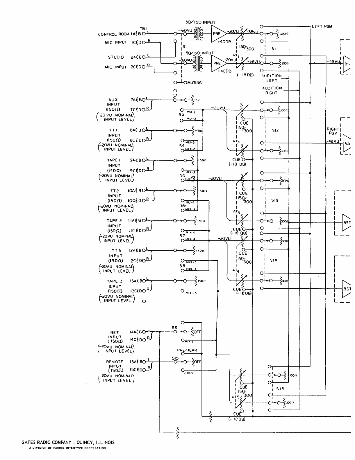
50/150~INPUT
O()--------,LE'FT
PGM
TBll
~60VU
II
PRE
-i:f)JU -
~I
~oon
CONTROL
ROOM
I
At
B
0"""---
~
r _
MIC INPUT
IC~
I)
I I I ,
:u
I
+4008
OH-I----
151
I
15
9300
,511
I
STUDIO
2A~8
L
_!G05~Q/ISIOI~~~~T
-<OV~I~
V~:----+----<t----.
:J'
o-+oVV
~
PRE.
~3e.VU01-o----1!>OOa
-
48VU
.l.
0':>
MIC
INPUT
2C~
oo-B--,
-I
+4008
0 U_.
~
(-
1308)
AUDITION
_ : _ LE.FT -
u-'-UMUTING
o AUDIT
10N_t--t
RIGHT
AUX
7A~B:srL"""---~-{I~;"
V
INPUT
-2uVU
~/
"
---"""'_S
(15011)
7C~
0 R
5Qr3~"''''-IX''''''-2,.....-+--~c....:....:;i;:-''-~Ar---v-r-vsj(lOil
(
20
VU
NOMINAl\
"'v
MllC-2
!
~o.:-
0:
INPUT
LE
V~L)
I CUE I
TTl
SA(
B L
I'on
I
300
I SI2
INPUT
I I
~
115~
I
(l50n>
8C~
0 R
MIM-l
A~2
<;
~
0 I
f-2OVU NOMINAl\
54
\.
.J.
Y :
~-----"S
~
INPUT
LEVEL)
v""'"
MI
x-z
O--..u
S
300iI
i/?
CUE
~
0'----+-
....
(-
18
DB)
TAPE I
9A(
B
::JrL'---,...---o--o-i
INPUT
1SOil.
(l'Som
9C~D
R
~X-3
0
(-2QVU NOMINAL'
Sc5~MUillC~r!l,..._--=-.:i!!:;!0.!..VU!L..,r-_7'Ycs-_+-_""'o-,._0-
,....-::3...;3('C'~1
\ INPUT LEVEt,I V , r
_b:-
-I
~
>
TT2
IOA~B~150n
ICUE
V:
!NPU T
1159(
I
513
(150
n.>
10Ce 0 R
MI1-4
r--
I
300
I
(-ZOVU
NOMINA~
~
A~
___
I
INPUT LEVEL
\.
13V
VI
TAPE 2
IIA~B~I~on
'----IVI----,l(-?.---t---I.(')u--L..o+n
INPUT
~(~
O----t----9
(150n)
IIC
~D
R
MIX-4-
(_~~
~
8)
0
!-20VU
NOMINAL\
5""'n7~M!.LIIX~_.!!.4
__
~_-~2.::::;O~V~U
__
-j
<~f--t---I~o-r.-cI---:3.~
\ INPUT
LEVEL)
V"
t1'
~
5"
TT3
12AE.B~I.,on
'C~:
INPUT
R
'15<}.:
I
SI4
(150n)
12ee 0
MllC-":"""~
---1--,
I
300
I
(-20VU NOMINAU
S~
Mlx-"
A
~4
:
\ INPUT LEVEL I v 0
!v
~
TAPE
"3
13A(B~I~OIl
i/~
_
_.
$!OO~
INPUT
CUE~
0
(I
50
n)
13C~D
R
MIX_~---"1
(-IBDB)
1-2oVU NOMINAL\
\
INPUT
LEVEL)
0
o
NET
14AtB~OFF
~
~
~~~
14C
~
ooEJ
I Omx-!--I----..
(-2':>VU NOMINAL\ '
PRE-HEAR
.NPU T
LE
VEL}
vn---
....
L
5~
REMOTE I
~At
B
'-'
-'-'
-
~OH
IN
r:'lJ T
Rn-
.....---t-------
(l'Son)
15C~D
v
M1X
_'5
(-20VU
NOM.
NAt.:)
\ INPUT
LEvEL
GATES
RADIO
COMPANY
-
QUINCY,
ILLINOIS
A DIVISION
OF
HARRIS-INTERTYPE CORPORATION
O
.....
I---+---t-----'
1---~Vf--I---oH
30011
/~
01
,
:
~CUE
I I
515
I 1
59.:
.i
AT,)
-
300
.........1-;lY.f---r--ol-oi
YX)n
I
~
o~---~
(-
I~'
DB)
I-
I
RIGIHI
PGM
:"
-4SVJJ.
p'
I
...
~
IV
L
__
,---
I
I
I
:"
~
BSt
'V
L
__
r--
I
I
I
I
'""
I
as'
Iv
L
__
Table of contents
Other Gates Radio Company Music Mixer manuals


