Gates Radio Company 994-6158-02 User manual

INSTRUCTION BOOK
For
The Executive
994-6158-02 Stereo Transistor Console
IB-888-0939-001 Gates Radio Company
6/26/1962 Quincy, Illinois

.TIgL
:t'XECU,:£IVE
,2,94
6158
002
STEREO
}lRAl'1SISTOR
CONSOLE.
INDEX
Page
SF
EOIFIG.ATIONS
..............................
1-,2
INTRODUCTION
....................................
••
•
•••••••••••••
0
•••
0
...........
0
.1
2
.Arlbi,ent
Tenperatures
...................................
3
Cable
and
Conduit
IJayout
••••.•••..••••.•
3
Grounding
Circuits
.........................................
4
Balanced
and
Unbalanced
Lines
•••.••.••.•
5
ctrcuit
Iopedances
......................
5
INSTALLATION
\.JIRING
..
OJ
..
"
.........................
..
6
Power
Connections
.........
oR
....
"
......
,.
.....
00'
• • 6
Studio
Intercon
"lJiring
•••••••••.••••.•••
6
Monitor
Speakers
......
G.................
7
Microphone
Input
Connections
••••••••••••
7
Turntab.le
Inputs
••.••..•.•...•..•..•.•••
9
Tape
Inputs
....
II'
......
"
................
,.
• " • " • •
10
Renote
Inputs
..................
""
....
"........
10
Ne'bwork Inpu't"
............
".................
11
Heno
Input
...................
0 • • • • • • • • • • }.1
Line
Output
Connections
,,' •
••••
• • • • • • • • • • •
11
Earphone
Connections.....................
11
OPERATION
••••••••••••••••••••••••••••••••••
11
Microphone
Selector
Switches
••••••••••••
11
Turntable
Switching
.....................
12
Tape
Input
Switching
••••••••••••••••••••
12
Renote
Input
Switching
••••••••••••••••••
13
Network
Input
•..••
~~
•.
a
•••
&.A.~~~~
••
_.&
~3
NenD
Input
.................•..•.......••
1.4·
Monitor
Input
Selector
and
I,evel
••••••••
14-
Line
imp
Input
Se.lectors
••••••••••••••••
14
Master
Gain
Contro.ls
•••••••••.•••.••••••
15
Cue
..
·lntercoD
Sys
ten
....................•
15
VU
Meter
Switch
................•........
16
Headphone
Jacks
.......................•.
16
PRINCIPLES
liND
TH.:GORY
OF
OPERATION
•••••••••
16
Trf?nsistor
ADplifi.er
Circuitry
•••••••
~
• •
17
Cue·-IntercoI1
Systell
•...................•
17
/
The
Executive
6/28/62
-1-
Simultaneous
Feed
to
Line
Amp.
2 & ,
..........
.
Mixing
System
•................•.......•...•.•.•
VU
Meter
and
Isolation
Pads
••••••••••••••••••••
Relay
Deck
•.•••.••..•••••••...••••.•.••••.•••••
Speaker
I~latching
Transformers
................••
Regulated
Power
Supply
& .Power
Transformer
•••••
MAINTENANCE
••••••••••••••••••••••••••••••••••••••••••••
Voltage
Measurements
•...•••..••.•••.•.•.••..•••
Mechanical
Components
•••.......•••.•••••••.••••
MODIFICATIONS
•.••.•••••..••••...•••••••.•..••••••••••••
Patch
Panel
Faciliti.es
•••.•••••••.•••••••••••••
Muti,ng
Relays
••.•..•...•••••.••••...
'"
..•.••••.•
Stereo
Network
Operation
•..•...•••...••••.•••..
PARTS
LIST
PARTS
LIST
DRAWINGS:
.........................................~ ...
-
M6205
Regulated.
Power
Supply
•••••••••••••
842 3492
001.
-
Functional
Block
Diagram
852 5854 001 -
Console
Schematic
826
8534 001 -Component
Layout
813 7290 001 -
Microphone
Input
Connections
/
18
18
18
18
19
19
19
19
20
20
21
21
22
1·-4
1
81,
7289 001 -Power
Transformer
& Warning
Light
Connections
813
7,00
001 -
Monitor
Speaker
Connections
813 7721 001 -
Earphone
Jack
Connections
842
,485
001 -
Schemati.c,
M6205
Regulated
Power
Supply
INSTRUCTION
BOOKS:
6/28/62
M-5700A
Transistori.zed
Program
Amplifi.er
M-6034
Transistorized
Console
Preamplifier
M·-60'5
Transistori
zed
Cue-Intercom
Amplifier
M-6108A
Transistori.zed
Monitor
Amplifier
-2-
The
Executive
Console
GAIN:
/
SP-",CIFICATIONS
---
THZ
.r1X.ii:CUTIVE
.994
6158
..
002
STEREO
THAN3IST03 CCN:30LE.
Remote/Network
to
:Line
Out:
50
DB
+ 2
DB
Remote/Network
to
Speaker:
58
DB
minimum
Microphone
In)ut
to
Li.m;
Output:
102
DBt2
DB.
Turntable
Input
to
Line
Output:
56
DB
'+2
DB.
Microphone
Input
to
Speaker
Output:
106
DB
mlillmum.
Turntable
Input
to
.Speaker
Output:
64
DB
minimum.
FREr",UENCY
R:GS.20NSE:
(1
KC
Reference)
+1.0
DB
from
30
to
15,000
cps
in
all
regular
program
circuits.
:!;2
DB
from
30
.to
15,000
cps
in
all
emergency
program
circuits.
+1.5
DB
from
30
to
15,000
cps
in
all
monitoring
speaker
circuits.
HARMONIC
DISTORTION:
0.5%
maximum,
30
to
15,000
cps
@ +8
DBI-I
output
on
all
program
lines.
0.5%
maximum,
50
to
15,000
cps
@
+18
DBl'1
output
on
all
program
li.nes.
1.0%
maximum,
50
to
15,000
cps
@
+39
DBn
(8
watts)
output
on
all
monitoring
speaker
outputs.
1.l'1. DISTORTION:
NOISE:
0.596 maximum
(llO/7000
cps
@
4:1)
@+8
DErl
egui.va1ent
sine
wave
output
on
all
regular
program
circuits,
1.5%
maximum @
+18
DBl'1
out.
1.
0%
maximum @
+39
DBrl
equivalent
sine
vlave
output
on
all
monitoring
speaker
outputs.
-122
DBl'1
relative
i.nput
noise
on
mi.crop]:lOne
channels
•
..
·75
DBl'1
relati.ve
input
noise
on
turntable
cha=els.
CROSST.ALK:
Below
noise
leve1
in
all
stereo
cha=els.
CHANNELS:
10
Stereophonic.
Rev.
3/23/64
The
Executive
-1···

/
SPECIFICATIONS
CONT'D.
INPUTS:
6
stereo
mics,
4-
stereo
turntables,
4-
stereo
tapes,
4 mono
remotes
and
1 mono
netvlOrk
(can
be
wired
for
stereo),
and
1
high
level
aUA"i.liary
stereo
input.
OUTPUTS:
Program
left,
program
right,
program
compatible,
.3
stereo
speaker
lines
with
muting
(plus
one
optional~,
1
stereo
speaker
line
Vii
thoUG
muting
2
studio
intercom
speaker
lines
and
2
phone
jacks.
TOTAl,
TRANSISTORS:
SIZE:
2N1307
2N4-22
2N14
14-
2N2l4-
2N1l83
2N1225
2N1539
Qty.
2
Qty.
10
Qty.
4-3
Qty.
5
Qty.
8
Qty.
2
Qty.
6
To·tal
76
53}?"
long,
11·_·3/8"
hi.gh,
17-·3/8"
deep.
Net
weight-
107
lbs.
-2-
The
Executive
INTRODUCTION
The
Gates
994
6158
002
Stereo
Control
Console
is
a
versatile
and
efficient
ten
channel
audio
control
center
especi.ally
designed
to
fill
the
need
for
such
equipment
created
by
the
establishment
of
FM
stereo
broadcasting.
This
console
provides
for
the
nixing
cueing,
and
moni
toring
of
a
variety
of
program
sources.
These
sources
include
microphones,
turntables,
tape
recorders,
remote
pickups,
and
networks.
These
signals
are
fed
to
the
two
stereo
channels
in
the
transmitting
system.
Due
to
the
flexibility
of
the
console,
other
combinations
of
out·-
put
feeds
are
also
possible.
.Provisions
are
inCluded
for
the
ad·-·
dition
of
a
third.
output
channel
so
that,
simultaneously
with
the
Fl'I
stereo
program
feed,
a
compatible
signal
(combination
of
left
and
right)
may
be
fed
to
the
A.."1
transmitter.
This
third
channel
may
also
be
used
to
broadcast
a
completely
different
monophonic
signal
to
the
Al"I
transmitter.
\men
stereo
programs
are
not
being
broadcast,
the
two
output
channels
of
the
console
may
be
used
t;o
feed
a
monophonic
signal
to
two
transmitters
simultaneously,
or
two
completely
different
programs
may
be
handled
at
once.
Microphone
input
sl-,i
tching
is
arranged
so
that
a
single
microphone
can
feed
both
channels
for
isolated
monophonic
announcements
on
stereo
broadcasting.
Or,
two
microphones
can
be
used
for
stereo
announcements.
Stereo
monil;oIing
of
ooth
bhe
program
output
and
the
audition
bus
is
provided,
as
w·e.lI
as
an
external
stereo
monj.·-,
tor
ampli.fier
input.
More
details
on
the
operation
of
the
console
may
be
found
in
the
section
of
this
book
titled
OP'G'RATION.
The
console
is
completely
transistorized
and
self,-contained
except
for
the
power
transformer,
which
h8.s
been
placed
externally
to
minimize
hum
pickup
in
the
console
and
the
earphone
jack
panel.
Breaki.ng
and
jumpering
of
all
major
circuits
allows
full
use
of
normal
ling
jack
fields,
with
all
comlections
brought
out
to
ter'--
minal
blocks
for
ease
of
installation
and
fu'ture
circ'.lcit
check-.
ing.
Three
speaker
muting
and
warning
light
relays
are
supplied
with
provisions
included
for
the
add.ition
of
a
fourth
relay.
Compensation
of
si.gnal
levels
by
the
use
of
fixed
pads
throughout
the
console
minimizes
the
necessity
of
readjusting
gain
controls
\'I"hen
switching
from
one
c
ircui
t
to
another.
The
cue,-intercom
system
provides
cueing
of
turntable
and
tape
sources
as
well
as
intercom
faci.lities
between
the
control
room
and
each
of
the
studios
as
v,el1
as
the
remote
lines.
The
cue-
intercom
system
is
interlocked
with
the
speaker
muting
relays
so
that
cueing
and
intercom
signals
cannot
inadvertently
get
on
the
air.
The
.Executive
6/26/62
....
1--

This
introduction
has
touched
on
some
of
the
more
important
points
of
the
console
to
give
gene:cal
information
Vii
thout
excessive
de-.
tails.
Those
concerned
with
the
daily
operati.on
should
study
I;he
section
labeled
OP...otul:J'ION.
The
insta.Llation
cre"l
should
study
their
section
before
actually
starting
the
Vlork.
Bach
section
is
broken
down
to
cover
different
phases
so
that
unnecessary
confusion
may
be
eliminated
and
the
answer
to
any
particular
question
may
be
easily
found.
'1'he
engineering
staff
is
urged
to
become
acquainted
with
all
sections
so
that
they
can
advise
other
groups
in
the
best
performance,
as
\vell
as
being
able
to
keep
the
console
in
top
operating
condi.tion.
INSTALLATION
All
the
packing
material,
including
any
shipping
frames
and
plat-
forms,
should
be
carefully
removed
prior
to
the
installation
of
the
J:16158
..
l
Stereo
Control
Console.
The
removable
items
include:
6 994
6034
OOl
Transistor
Preamp1ifi.ers.
2
994-
6034 001
Transistor
Booster
Ampl
i f
i.ers
(same
as
the
Pream,;lif
iers).
2
994-
5700
001
'I'rans
istor
Program
Amplifiers.
1
994-
6035
OOl
Transistor
Cue···
Intercom
Amp
Ufier.
1
992
1335
001
Phone
Jack
Plate.
1
472
0429
000
Power
Transformer
1
646
0379
000
Group
of
Knob
Decals.
1
888
0939
001
Insi.;luccj,Oll
i'lanualo
If
any
of
the
i'ems
listed
above
are
missing,
search
all
of
the
packing
materi.al
again
to
determine
if
they
have
been
overloolwd.
If
still
missing,
contact
the
Gates
Hadio
Company
for
instructions.
SIZE:
deep.
The I16158A
Console
is
53-1/2"
long,
11,·3/8"
high
and
17.-3/8
11
The
net
weight
is
107
pound.s.
With
the
plug-in
amplifiers
removed,
place
the
console
on
the
con-
trol
desk
in
the
final
operating
positi.on.
Determine
the
routing
of
the
interconnecting
cables
into
the
cabinet
and
the
method
of
co=ecting
the
cables
to
the
control
desk.
The
conduit
and/or
duct
layout
should
also
be
considered
in
the
pla=ing
of
the
interconnecting
cable
runs.
If
the
cables
are
to
come up
through
the
surface
of
the
desk,
mark
the
cable
access
holes
(in
the
con-
sole
base)
on
the
desk
top
so
they
may
be
accurately
drilled
after
removal
of
the
cabinet.
In
some
cases,it
is
preferred
to
elevate
the
console
cabinet
sufficiently
to
permit
the
cables
to
lay
between
the
desk
top
and
the
console
base,
making
a
right
angle
turn
'-lith
the
cables
to
enter
the
cabinet.
The
cables
are
then
dressed
off
the
rear
of
the
desk
and
generally
a
protective
cover
is
installed
down
the
rear
of
tho
desk.
6/26/62
-2·-
The
Executive
In
either
type
of
i.nstallation,
the
console
should
be
fastened
securely
to
the
control
desk
after
the
wi:ring
is
complete.
This
is
facilitated
by
the
holes
in
the
center
of
several
of
the
large
dimples
jn
the
cabinet
base.
The
wiring
adjacent
to
the
mounting
holes
should
be
fully
protected
during
the
securing
operation.
The
transistor
amplifiers
and
the
power
sup;Jly
used
in
the
conso:le
have
been
designed
for
reliable
operation
at
temperatures
up
to
55°
C.
or
131°
F.
No
special
ventilation
is
required.
HO.lever,
prolonged
sine
wave
testing
(especially
in
the
monitor
amplifiers)
should
be
avoided
to
allow
heat,
built
up
in
the
power
output
transistors,
to
be
dissipated.
See
the
instruction
books
provi-
ded
at
the
end
of
this
manual
for
more
information.
Cable
and
conduit
layout
is
of
utmost
importance
in
the
studio
installation.
Good
results,
with
a minimum
of
noise
and
cross·_·
talk,
require
careful
planning
and
construction.
A
system
hastily
installed,
VIi
thout
thorough
planning.,
i.nvari.ably
results
i.n
con·_·
ti.nuous
trouble
unti.l
rebuilt.
First,
the
matter
of
signal
levels:
Cables
should
generally
be
di.
vided
i.nto
three
groups,
low
level
cabl
es
may
include
levels
from
·-60
DBi'1
to-·20
D13N.
Nedium]
evel
cables
may
include
levels
from
·-20
DBrl
to
+14
DEl'i.
The
high
level
cable> may
include
levels
from
+14
DEI"!
to
+40
DBN.
AC
power
wiring
should
be
run
in
sepa·-
rate
cables.
vJhenever
possible,
do
not
run
any
of
the
four
cables
listed
in
a
conduit
along
with
cables
of
different
level
classification.
If
two
or
more
cabl0s
must
be
run
in
a
COilliilon
conduit,
never
exceed
a
difference
of
40
db
in
level
bet,veen
the
highest
and
thE)
lowest
level
in
either
cable.
Use
high
quali.ty
shielded
twisted
pair
for.
all
audio
wiring,
such
as
Gates
catalog
number
1261.
For
all
microphone
wiring
and
long
medium
level
cable
and
conduit
runs
the
use
of
rubber,
p19.stic
or
cloth
covered
shielded
pairs
elim--
inates
multiple
ground
.Loops
and
the
resultant
noise
problems.
Gates
catalog
number
8440
microphone
cable
is
reco=ended.
In
parallel
cable
runs
of
different
levels,
the
most
important
aid
i.s
physical
isolation.
Up
to
six
inch
spacing
is
preferred.
If
there
is
not
room
for
this
isolation,
do
not
lace
all
of
the
wires
in
the
same
cables.
Keep
the
cables
laced
separately
for
the
di.fferent
level
classi.fications
even
if
two
or
more
must
lay
together.
This
will
give
much
better
isolation
than
when
formed
into
one
cable.
The
deviations
from
the
preferred
methods
must
not
be
taken
lightly.
Use
them
only
as
a
last
resort,
not
just
for
convenience.
The
Executive
6/26/62
-3-

/
Terminal
layout
is
arrangsa.
~n
thci
console
to
allow
adequate
separation
of
cablss
up
to
the
point
of
connectlng
to
the
ter-
minal
blocks.
Low
level
microphone
cables
connect
on
the
left
to
TBl.
Medium
.level
cables
connect
in
the,
cent8r
to
TB3.
High
level
cables
connect
to
TB4
and
(in
the
rear)
to
TB6.
Intercom
"Tiring
conn8ctions
are
brought
out
to
TB6
since
these
are
auxil.-·
iary
circuits
which
may
vary
in
level
from
-·50
DB
to
+28
DBN.
The
speaker
outllUt
cables
are
hi.gh
level
and
should
not
be
run
with
low
level
cables.
Conduit
generally
affords
enough
shielding
so
that
different
levels
in
separate
condui.t
presents
no
isolati.on
problem
sven
wi
thout
spaci.ng
them
apart.
liicrophone
level
condui
t
and
speaker
level
conduit
can
probably
run
along
tog8ther
with
no
crosstalk.
HovlBvor,
if
practical,
it
is
advisable
to
maintain
physical
separation
and
add
to
the
safety
of
the
installation.
Fower
Circuits,
especially
those
with
high
current,
should
not
be
in
close
proximi
ty
"lith
program
carrying
conduit;
elec
tro-
mag'letic
shielding
is
poor
in
most
conduit.
Grounding
circuits,
like
cable
layout
and
most
systems
work
methods,
are
unpredictable
to
a
certain
extent.
Therefore,
no
hard
and
fast
rules
apply
100%
of
t;he
time.
In
this
section
it
is
attempted
to
cover
the
things
to
avoid
and
to
present
gener-
ally
accepted.
:practices
tbat
always
give
good
J.:esul
ts,
Ol-'
all.cv;
good
results
to
be
obtained
,vi
-eh
minor
modii
ication,
Entir'ely
dif
ferent
approaches
have
been
used,
some
with
good
results,
but
unless
you
are
an
expert
on
the
subject,
most
are
risky.
The
console
grounding
system
i.s
based
on
the
one
point
ground.
Different
circuit
grounds
are
insulated
from
the
chassis
and
other
grounds
except
at
one
point,
where
they
all
join
together
and
go
to
earth
ground.
This
system
.prevents
multiple
ground
loops
vii
th
the
result
ing
hum
pickup
from
Circulating
currents
~nd
l~F
pickup
and
regeneration
•
.
External
circuits
connected
in
the
console
should
not
destroy
this
system.
Microphone
circuits
are
not
grounded
in
the
con--
sole.
The
shi.elds
should
not
be
grounded
externaLly
except
after
noise
checks.
They
may
then
be
grounded
if
better
results
are
obtained.
'rurntable
and.
tape
inputs
are
unbalanced
and
the
common
side
is
grounded.
If
the
inputs
are
unbalanced,
the
common
side
should
connect
to
the
back
row
of
the
terminal
blocks
(IB,
2B, 3B,
etc.).
If
the
input
circui.t
is
grounded
external
to
the
console,
the
ground
should
be
1
if
ted
if
pos-"
sible
to
prevent
ground
loops.
If
the
ground
cannot
be
re-·
moved,
or
if
tho
circui.t
impedance
,"111
not
match
the
600
ohm
input,
a
matching
transformer
should
be
used.
Order
Gates
A·-21
line
matching
and
isolation
transformer.
The
Executive
6/26/62
-4·-
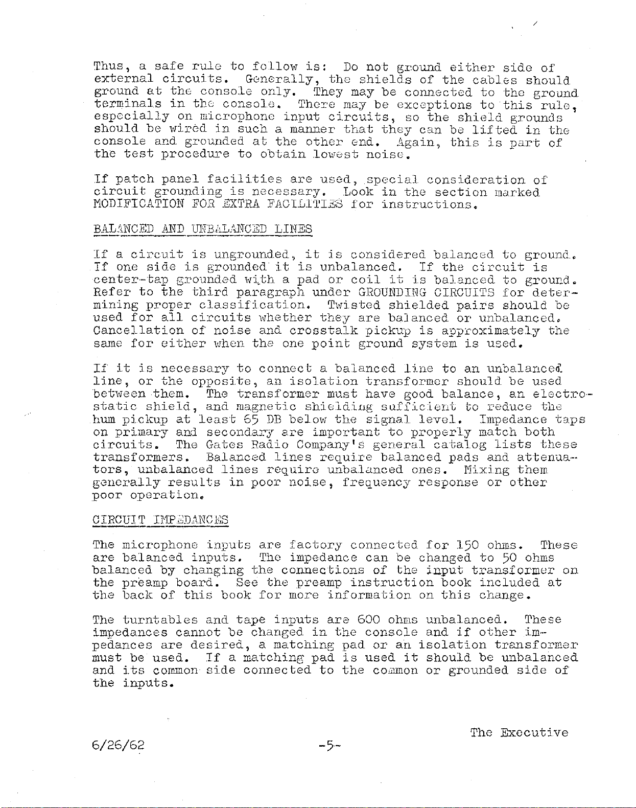
Thus,
a
safe
ru1e
to
follow
is:
Do
not
ground
either
side
of
external
circuits.
GGn8rally,
the
shields
of
the
cables
should
ground
at
thG
console
only.
They
may
be
connected
to
the
ground
terminals
in
the;
consolD.
TheI'e may
be
exceptions
to
this
ru18
esp8cially
on
microphone
input
circuits,
so
the
shield
grounds'
should
be
wirGdin
such
a
manner
that
they
can
be
lifted
in
the
console
and
grounded
at
the
other
end.
Again,
this
is
part
of
the
test
procedure
to
obtain
lowest
noise.
If
patch
panel
facilities
are
used,
special
consideration
of
circuit
grounding
is
necessary.
.Look
in
the
section
marked
MODIFICATION
FOR
EXrpRA
FACI.Ll'1'Iji;3
for
instructions.
BAL"NCED
AND
UHBALANCED
LINES
---,--------,----
If
a
circuit
is
unground.ed,
it
is
considered
balanced
to
ground.
If
one
sicle
is
grounded
it
is
unbalanced.
If
the
circuit
is
center,,·tap
grounded
'v1..th a
pad
or
coil
it
is
balanced
to
ground.
Refer
to
the
third
paragraph
under
GHOUNDING
CIRCUITS
for
deter-
mining
proper
classification.
THisted
shielded
pairs
should
be
used
for
all
circuits
whether
they
are
ba]anced
or
unbalanced,
Cancellation
of
noise
and
crosstalk
pickup
is
app:coximately
the
same
for
either
"Ihen
the
one
point
ground
system
is
used.
If
it
i.s
necessary
to
connect
a
balanced
line
to
an
unbalancea~
line,
or
the
opposite,
an
isolation
transformer
should
be
used
betvieen
them.
The
transformer
must
have
good
balance,
an
electro-·
static
shield,
and
magnetic
shi.eldillg
sClffic..ient
to
reduce
the
hum
pickup
at
least
65
DB
below
the
signal
level.
Impedance
t;:lPS
on
pri.mary
and
secondary
are
important
to
properly
match
both
circui
ts.
The
Gates
Radio
Company I s
general
catalog
lists
tllGse
transformers.
Balanced
lines
requiTe
balanced
pads
and
attenua--
tors,
unbalanced
li.nes
requiro
unbalanced
ones.
Mixing
them
generally
resul.ts
in
poor
noi.se,
frequency
response
or
other
.poor
operation.
CIRCUIT
HlP.2DANCBS
The
mi.crophone
inputs
are
factory
connected
for
150
ohms.
These
are
balanced
inputs.
The
impedance
can
be
changed
to
50 ohms
balanced
by
changing
the
co=ections
of
the
input
transformer
on
the
preamp
board.
See
the
preamp
instruction
book
included
at
the
back
of
this
book
for
more
informati.on
on
this
change.
The
turntables
and
tape
inputs
are
600
ohms
unbalanced.
These
impedances
cannot
be
changed
in
the
console
and
if
other
iill-'
pedances
are
desired,
a
matching
pad
or
an
isolation
transformer
must
be
used.
If
a
matching
pad
is
used
it
should
be
unbalanced
and
its
common
side
connec
ted
to
the
CO';11Ilon
or
grounded
side
of
the
inputs.
The
Executive
6/26/62
-,5-
/
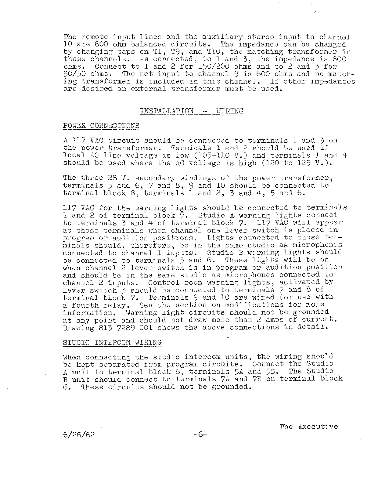
The
remote
input
1
ines
and
the
auxiliary
stereo
input
to
chanr181
10
are
600
ohm
balanc8d
circuits.
The
impe;danc8
can
be
changed
by
changing
taps
on
Tl,
T9,
and
']'10,
the
matching
transform",r
in
thes0
channo1s.
riS
connectod,
to
1
and
3,
the
impedance
is
600
ohms.
Connect
to
land
2
for
150/200
ohms
and
to
2
and
3
for
30/50
ohms.
~rhe
net
input
to
chann01
9
is
600
ohms
and
no
match",
ing
transformer
is
included
in
this
channel.
If
othor
i.mp",dancus
are
desired
an
external
transformer
must
be
used.
INSTALLATION
___
,!IHINQ
PO'JER CONlBC'T'TONS
A
117
VAC
ci.rcui
t
should
be
connect0d
tc
terminals
1
and
3
on
the
power
transformer.
'[,erminals
1
and
2
should
be;
used
if
local
AC
line
voltage
is
low
(105,-110
V.)
and
t0rmi.nals
1
and
4
should
be
used
where
the
AC
voltage
is
hi.gh
(120
to
125
V.).
The
three
28
Vo
secondary
windings
of
the
powGr
transformer,
terminals
5
and
6,
7
and
8,
9
and
10
should
be
connected
to
terminal
block
8,
terminals
land
2,
3
and
Lj,
5
and
6.
117
VAC
for
the
warning
li.ghts
should
be
connected
to
terminals
1
and
2
of
terminal
block
7.
Studio
A
warning
lights
connect
to
terminals
3
and
4
of
terminal
block
7.
117
vAC
will
appe3.r
at
these
terminals
when
channel
one
Lever
mii
tch
is
placed
in
program
or
audition
posi
liiODS.
T,i.ghts
conn0cted
to
theSE'
t8l"-
mina1s
should,
therGfore,
be
i.n
tho
same
studio
as
microphonos
connected
to
channel
1
i.nputs.
Studi.o
B
w'lrning
lights
should
be
conn8cted
to
terminals
5
and
6.
Those
li.ghts
wi11
be
on
"lhen
channel
2
lever
sl'J"itch
is
in
program
or
audition
positi.on
and
should
be
in
the
same
studio
as
microphones
conn8cted
to
chanrlel
2
inputs.
Control
room
1rrarning
lights,
ac
ti
vated
by
lev6r
switch:;'
should
bG
connocted
to
terminals
7
and
8
of
terminal
block
7.
Terminals
9
and
10
are
wired
for
use
with
a
fourth
relay.
See
the:
section
on
modifications
for
mor'e
information.
\~arning
light
circuits
should
not
be
grounded
at
any
point
and
should
not
draw
mOLe
than
2
amps
of
current.
Drawing
813
7289
001
shoW's
the
above
connections
in
detail.
STUDIO INTERCOTL
'JIRlNG
\Jhen
connecting
the
studio
i.ntercom
units,
the
wiring
should
be
kept
separat'2d
from
program
ciI'cui
ts.
Connect
the
Studio
A
unit
to
terminal
block
6,
terminals
5A
and
5B.
The
Studio
B
unit
should
connect
to
terminals
7A
and
7B
on
terminal
block
6.
These
circuits
should
not
be
grounded.
The
.c!,xecutive
6/26/62
/
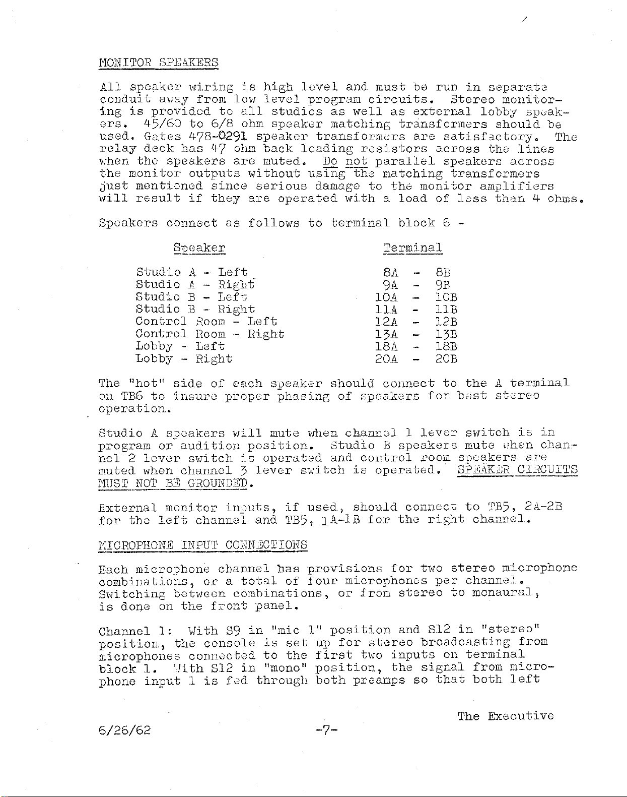
MONITOR
SPEAKERS
All
speaker
Hiring
is
high
level
and
must
be
run
in
separate
cOllduit
m;ay
from
10Vi
level
program
circui.ts.
Stereo
monitor-·
ing
is
providod
to
all
studios
as
well
as
external
lobby
sp~ak
ers.
45/60
to
6/8
ohm
speaker
matching
transformers
should
be
used.
Gates
478-Q291
speaker
trans.formc:rs
are
satisfactory.
Tho
relay
deck
has
4-7
ohm
back
loading
resistors
across
the
lines
when
the
speakers
are
muted.
Do
got
parallel
sPeakers
across
the
monitor
outputs
without
using
the
matching
transfoI'mers
just
mentioned
since
serious
damage
to
th0
monitor
amplifiers
will
rccsult
if
they
are
operated
with
a
load
of
less
than
4
ohms.
Speakers
connect
as
folloVis
to
terminal
block
6
.-
9.1?S,
ak
£E
Terminal
Studio
A
.-
Left
8A
8B
Studio
A
,.,.
Right
9A
9B
Studio
B -
Left
lOA lOB
Studio
B
._.
Ri.ght
llA
llB
Control
300m
--
Left
12A 12B
Control
Room
.~"
Right
13A 13B
Lobby
-
Left
18A 18B
Lobby
.-
Right
20A 20B
The
"hot"
side
of
each
speaker
should
connect
to
the
A
termi.nal
on
TB6
to
insure
proper
phasing
of
speakers
fo:r
b8St
stcrc~Q
operation.
Studio
A
spoakers
will
mute
"Then
channel
1.
.l8ver
switch
is
in
program
or
audition
position.
Studio
B
speakers
mute
"hen
chan--
nel
2
.lever
switch
is
operated
and
control
room
speakers
are
muted. when
channel
3
lever
s.J1
tch
is
operated.
SP.t<;AKJ;B
CL~Q.QITS
MUST
NOT
BE
G'ROUND~~D.
-_
...
_--------
External
monitor
illj:;uts,
if
used,
should
connect
to
TB5,
21\.
..
-2:B
for
the
left
channel
and
TB5,
lA-.JB
for
the
ri:;ht
channel.
111CROPH0t:_~
I~
Cm~NJC!!9E§.
E3.ch
microphone
ch3.nnel
has
provisions
for
·two
stereo
microphone
combinations,
or
a
total
of
four
microphones
per
chaILYJ.el.
switching
between
com.binations,
or
frolli
stereo
to
monaural,
is
done
on
the
front
panel.
Channell:
\.lith
39
in
"mic
1"
position
and
S12
in
"stereo"
position,
the
console
is
set
UP
for
stereo
broadcasting
from
microphones
connected
to
the
first
hID
inputs
on
terminal
block
1.
1·Ji.th S12
in
"mono"
position,
the
signal
from
micro-'
phone
input;
1
is
fGd
through
both
preamps
so
that
both
left
The
Executi.ve
6/26/62
'-7-'
/
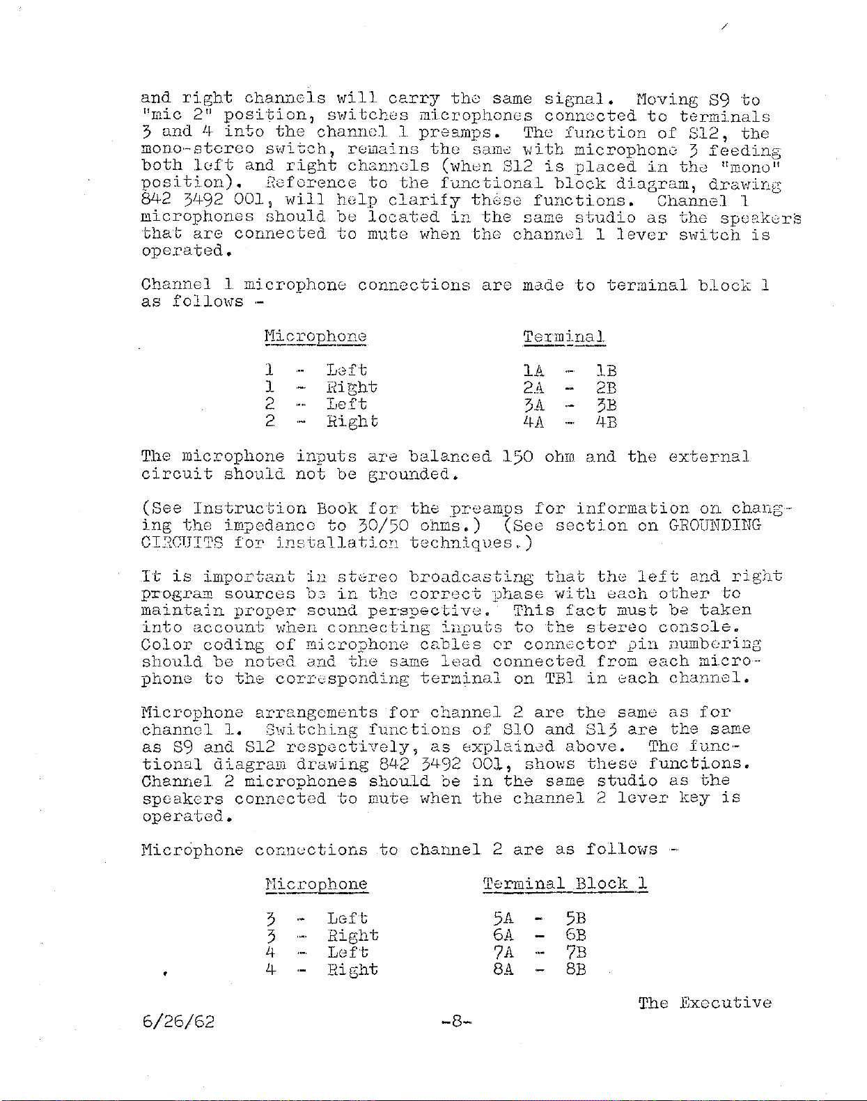
and
right
ChanI181s
will
carry
the
same
signal.
l'loving
S9
to
"mic
2"
position,
SVli-tch8S
microphones
connected
to
terminals
3
and
4
into
the
channell
pre3.mps.
The
function
of
812,
the
mono'-stcrco
switch,
remains
the
salla
with
microphone
3
feeding
both
1uft
and
right
char.ne1s
(vlhen
812
i.s
placed
i.n
th0
"mono"
position).
Refcrence
to
the
fUilctiona.l
block
diagram,
drawing
842
3492
001,
wi
11
hGlp
clarify
these;
functions.
Channel
1
microphones
should
be
located
in
the
same
studio
as
the
speakurs
that
are
connected
to
mute
when
the
channell
lever
sivitch
is
operated.
Channel
1
microphone
connections
are
mdde
to
terminal
block
1
as
follol'JS·-
-
1
1
2
2
Left
Flight
Left
Right
Terminal
11'.
2A
31'.
4A
IB
2B
3B
4B
The
microphone
inputs
are
balanced
150
ohm
and
the
external
circuit
should
not
be
grounded.
(See
Instruction
Book
for
the
preamps
for
informa
bion
on
chang·-
ing
the
impedance
to
30/50
ohms.)
(See
section
on
GHOUNDIIlG
CI.2CUIIJ.'S
fo!'
in~:tallation
techniql}8S
,_)
It
is
important
in
stGreo
broadcasting
that
the
left
and
right
p:r'ogram
sources
b3
ir.:.
th8
correct
'Dhase
Vii
tll
each
other
to
maintain
proper
sound
persp8ctivu.-
This
fact
must
be
taken
into
account
when
connecting
in.Quts
'to
the
stereo
console
..
Color
codi.ng
of
I'licrojJhone
cables
or
connector
pin
numb8ring
should
be
noted
and
the
same
lead
connectecl
fro];!
each
micro--
phone
to
the
cor'I'c;sponding
ter::ninal
on
TBI
in
each
channel.
Microphone
arrangements
for
channel
2
are
the
same
as
for
chann8l
1.
;3witching
fUIlcti.ons
of
S10
and
813
are
the
same
as
89
and
812
r8sp8ctively,
as
8xplained
8.bove.
Th8
fune·-
tional
diagram
drawing
8L
+2
3492
001,
shows
these
fUl1cti.ons.
Channel
2
microphones
shoU:ld
be
in
the
same
studio
as
the
speakers
conn8cted
to
mute
when
the
channel
2
lover
key
is
operat8d.
Microphone
cor.nections
to
channel
2
are
as
f0110Vls-,
6/26/62
3
3
4
4
LGft
Right
Left
Right
Terlu
i
119.l
Block
1
5A
61'.
7A
8.11.
5B
6B
7B
8B
The
Executive

Again,
proper
phasing
must
be
obta1ned
betvleen
microphones
for
best
operation.
Switches
S11
and
814
perform
the
same
functions
as
S9
and
S12
respectlvely,
as
explained
under
channel
1..
Channel
3
micro·-
phones
should
be
in
the
same
studio
as
the
speakers
connected
to
mute
when
the
channel
3
lever
s1l1i
tch
is
operated.
Again,
phasing
of
inputs
is
important
and
microphone
polarity
should
be
closely
observed.
Connections
should
be
made
as
follows
'.'
Microphone
Terlll2:nal
Block
_1
5
Left
9A
9B
5
Right
lOA lOB
6
Left
llA
llB
6
Right
12A
12B
Drawing
813
7290
001
shows
the
above
microphone
connections.
Provision
i.s
made
for
four
stereo
turntable
inputs,
eaoh
of
\,hich
can
be
mli
tohed
to
mixers
4
or
5.
Turntabl
e
inputs
are
medium
level
(..-20
DBI1)
600
ohm
unba.lanced.
If
the
output
of
turntable
preamp
is
unbalanced,
the
common
side
should
be
con-
nected
to
the
common
si.de
of
the
input
termi.naJ.s
(ROI, B)
on
terminal
block
;;.
. As
with
mi.crophone
inpu'~s.
polari.ty
of
the
turnto.'blo
1.np::::8 r:u.st
be
observed.
to
insure:; t::.2::
!li.ght
SJ:;!,Q
left
channel
si.gnals
are
in
proper
phase
relationship.
This
requires
checki.ng
of
all
the
~dring
from
the
stereo
pickup,
through
the
preamp
to
the
console
for
proper
connections,
Inputs
to
the
turntable
chann.els
should
not
be
ground.ed
ex·-
ternally,
Isolation
transformers
may
be
used.
if
necessary
to
isolate
external
groUllds
or
to
connect
i.nputs
that
should
not
be
grounded
to
the
unbalanced
turntable
i.nputs.
Turntable
inputs
connect
to
terminal
block
3
as
follows
.•
,
.Tur~le
.Terminal
!i
1
Left
Channel
lA
IB
1
Right
Channel
2A
2B
2
Left
Channel
3A
3B
2
Right
Channel
4A
4B
3
Left
Channel
5A
5B
3
Right
Chanr!el
6A
6B
4
Left
Channel
7A
7B
4
Ri.ght
Channel
8A 8B
See
the
section
on
OPERATION
for
detai.ls
on
switching
functions.
6/26/62
-9-
The
Executi.ve

/
TAPE INPUTS
..
_---
Four
stereo
tape
inputs
aI''''
provided,
S\·Jitchable
bctweGrl
chan-·
nels
6
and
7.
ThGse
are
"mGdi.um·-level"
600
ohm
unb;ilcnc
cd
inputs.
Connecti.ons
arE:
made
to
terminal
block
3
as
follO"l'lS
.-
1
1
2
2
3
Tape
Left
Right
Left
Eight
~=
Left
Right
Left
Right
Torminal
._----
9A.
lOA
llA
12A
13A
14A
15A
16A.
9B
lOB
11B
12B
13B
14B
15B
1GB
As
with
othor
stereo
inputs,
tape
CODll.eC1;lOllS
must
be
mdde
1!lith
proper
polari.ty
to
insure
proper
phasi.ng
of
stereo
signals.
Alt;hough
the
console
is
intended
to
hundle
4
turntablc:s
and
1+
tapes,
lTIOre
than
thl
s
number
of
turntablos
may
be
used
by
connecting
to
tap'"
inputs
and
switching
them
into
mixers
6
and
7.
Of
course,
one,
or
morE:
of
the
tape
inputs
must
be
s3erj
f:i
ceCl
c
In
the
SU2:},e
manner,)
more
than
1.1-
tape
inyuts
can
'be
obtained
by
using
tUInte.ble
inputs
and
bri.nging
the
Cldcli·-
tional
tapes
i.nto
mixers
4
and
5&
In
thi
s
case,
one
ox-
more
turntable
inputs
will
be
sacrificed.
Of
course,
not
all
the
tape
or
turntable
inputs
need
be
used.
REI'10T
'E
INPUI'S
---.--
Provision
is
made
for
the
connec"tion
of
4
remote
lines
to
mixer
8.
These
are
"medium'"·level"
GOJ
ohm
bahmced
mono-
phonic
i.nputs.
Connections
for
these
inputs
are
locat8d
on
terminal
block
"3
as
follows
'.'
Remote
.ld.ll~
1
2
3
4
Terminals
-.
l?A
l8A
19A
20A
17B
l8B
19B
20B
It
is
suggested
that,
rather
than
connect
the
remote
~ines
directly
to
the
consol,),
they
be
brought
out
to
jacks
i
..
n
the
station
patch
panel
to
allow
a
greater
versatility
in
progra=ing.
2xternal
ciI.'cui'cs
should.
not.
be
grounded.
The
input
level
of
these
lines
should
be
about
·-20
DBl"I.
This
allows
the
use
of
isolati.on
pads
or
eou()'lizc)rs
and
still
have
sufficient
gain
for
proper
operation.
The
Executive
6/26/62
·-10-

NETWOR.1{
INPUT
A
600
0hI:!
monophonic
network
input
is
provided
with
mlxlng
accomp·_·
lished
through
L1ixer
9.
This
channel
can
be
converted
to
stereo
if
desired
(see
the
section
on
MODIFICATIOJlTS
for
details).
As
ltfired,
the
network
wi.ll
feed
both
left
and
ri
ght
program
channels.
The
network
line
should
be
connected
to
TB5,
teruinals
17A
and
17B.
NEl"I0
INPUT.
Channel
10
is
a
high
level
stereo
channel
provided
for
auxiliary
use.
Input
connection
should
be
made
to
TB5, 19A
and
19B
for
the
left
channel
and
TB5, 20A
and
20B
for
the
right
channel.
LINE
OUTPUT
COl\TNECrnOJITS
.
~.~------
The
level
of
these
lines
will
be
+8
DBM
and
they
should
be
routed
carefully
to
prevent
crosstalk
back
into
low
level
input
circuits.
Connect
output
line
1
to
TB4
terminals
1311.
...
l3B.
Output
line
3
connec
ts
to
TB4
terminals
15A
...
15B.
'Line
2,
if
used,
connects
to
TBLj-
terminals
l4A-·
l4B.
These
are
600
ohm
balanced
outputs.
Observe
correct
phase
relationship
between
output
lines
to
insure
proper
sOlmd
perspective
betl1een
left
and
right
channe1s.
In
..
-
structions
for
balancing
lef
t
and
right
channels
uay
be
found
i.n
the
MASTER
GAIJIT
CONTROLS
Section,
page
15.
-_._._-----------
EA;[i'PHOJITE
COJITJITECTIONS
The
earphone
jaeks
for
both
the
cue
..
intercom
system
and
the
line
monitoring
circuits
are
mounted
externally
on
a
jack
panel.
The
panel
should
be
mounted
in
a
convenient
location
in
the
control
room
and
shielded
tHisted
pair
should
be
used
to
connect
to
tho
console.
Drawing
813
7721
001
shows
the
cooplete
wiri.ng
details
necessary
for
proper
installation.
OPERAr;rIO~
The
arrangeoent
of
panel
controls
gives
maximum
versatility
to
console
operation
while
keeping
actual
operating
as
siLlple
as
possible.
Control
functions
are
explained
in
the
following
sections.
In
all
cases,
reference
to
the
block
diagran
of
the
console,
dral1ing
8423492
001,
will
help
clarify
these
functions.
MICROPHONE SELECTOR Sl-JITCHES
On
the
upper
left
side
of
the
panel,
above
channel
Llixers
1,
2
and
3,
are
three
pairs
of
switches.
These
switches
perforn
identical
functions
for
each
channel.
The
uicrophone
selec
..
·
tor
swi
tch
is
used
to
s\vi
tch
betwoen
t\'lO
sets
of
stereo
Llicro·-
phones
in
each
studi.o.
Wi
th
the
Llono·-stereo
sl1i
tch
in
the
6/26/62
-·11-· The
Executive
/
starGo
position,
the
left
and
right
Iilicrophones
vJill
be
switched
to
the
loft
and
right
prograB
bUSSGS
Nhan
the
proper
mixer
kc;y
is
placed
to
thG
right.
Those
same
microphones
v,il1
be
svritched
to
left
and
right
audition
busse)s
when
thG
mixer
key
is
placed
to
tho
left.
If
the)
mono-,stereo
sHi
tch
is
plac2d
in
the
Iilono
positi,on,
tho
left
microphone
will
feGd
both
left
and
right
program
or
3.udition
busses
when
the
mix(,r
key
is
placed
in
the
program
or
audi
tion
position.
This
al,-·
10vlS
announcements
to
be
made
on
both
channGls
while
broad,··
casting
stereo
frol1
other
lilicrophonG
combi,nations.
.For
stereo
broadcasting,
the
1
in8
output
sv/i
tch
must
be
in
"otereo
posi,·"
tion",
as
oxplainod
under
LINB
INFUT ScIiTCHING.
TU"INTABLB
.81,.jE'CHIHG
The
four
turntable,
switches,
abOV0
mixers
L+
and
5,
selGct
the
desired
input
to
each
mixer
< ',fIlen
thu
channel
switches,
above
mixer
4,
are
in
the
"o.FF"
position,
turntable
inputs
aro
nor""
malled
through
to
the
mixer
5
switches.
1,Jhen
any
of
the
svlitches
jn
channel
4
are
swi
tclled
"ON",
the
turntable
input
l,rill
ap'-'
pear
at
the
output
of
mix8r
4,<
Moving
the
channel
4
mixer
koy
to
the
right
"lil1
bring
up
tho
turntable
input
on
the
left
and
right
program
busses,
while
moving
tlw
mixer
key
to
th0
left
vlill
switch
tho
signal
to
the
18ft
and
right
audition
busses.
1'10ving
tho
desired
turntilble
in"ut
switch
to
the
"ON"
posi,-
tion,
above
mixer
5,
Hill
switch
thG
d8sired
turntable
input
into
this
mixer.
S
....
ri
tching
is
arrD.l1G2d
so
th.}
t a turnt::'1.ble
cannot
bil
s,li
tchcdinto
;;}ixer
5,
if
it
is
alree.dy
switched
into
mi
xor
4.
This
prevents
loading
the
turntable
outl}utby
paralleling
it
into
tl,'O
console
inputs.
Cueing
facilitieS
are
provided
for
by
turning
uither·turntClble
mixer
fadar
fully
c
ounterc}
ocll:wise.
This
co=cocts
tllG
turntab10
inputs
to
the
cue,-,intercom
amp.
Cuoing
can
be
accomplished
by
USIng
the
panel
IilOUlltcod
speaker
or
hoadphonos
(plugged
into
the
cue
phono
jack).
The
operati.on
of
the
cue-,intercom
system
is
covered
in
a
l"ctor
s0ction.
No
special
provision
is
nl,ces,-
sClry
for
monophonic
op0ration,
since
mono
records
played
on
a
storoo
turntable
vJill
result
in
idontical
signals
in
both
left
and
right
chann.]ls.
T,,;,p;§.
..
INFUT
S')I'T'CHING
Mixers
6
and
7,
located
to
the
right
of
the
VU
rueters'are
idGnt.ical
in
operation
to
the
turntable
inputs
discussed
above.
Four
storeo
inputs
can
be
switchod
to
either
mixers
6
or
7.
Outputs
of
mixGrs
6
and
7
can
-08
s'\,itched
to
"program"
or
"audi
tion"
busses.
Cuoing
f3.cilities
are
provided
by
turn,-
ing
mixer
6
or
7
fully
counterclockwiso,
thus,
connecting
the
mixer
to
th0
cue-·intercom
system.
Tho
Executive
6/26/62
-,,12,·-

/
RENOTE
INPUT
SlllTCHING
Four
le~er
s~itches,
located
~bove
mixer
8,
control
four
reDote
inputs.
The
re;]lOte
svJitches
provide
talkbBck
and
cueingfucil·····
ities
to
the
remote
operator.
In
the
center
position,
they
re-
ceive
pIogrclD
cue
sign3l
froel
the
moni
toring
a:J.plif
ier.
:The
level
is
adjusted
to
approxinately
+8
VU.
This
si6nal
is
fed
back
to
the
IeDote
operator
to
allow
hin
to
start
hi.8
progral:l
at
the
proper
time.
The
lower
position
is
the
;'Eix"
position
and
connects
the
remote
program
into
the
progra;J
or
audition
bus
through
Lli.xer
8.
The
upper
position
of
the
s\-litehes
have
a
terminati.ng
load
f
or
the
remote
lines
and
allo\'1
over·-,ride
and
talkback
iuncti.ons.
See
the
section
CUE·,IWij:!:RCOI1 dYS'l'EI1
for
explanation
of
these
functions.
The
remote
lines
are
not
tied
togeth"r
when
any
or
all
of
the
reLlote
keys
are
in
th"
talkback
posi
tion.
The~-e
is
sufficient
isola
ti
on
between
then
even
with
the
over,·ride
tie-in
on
all
lines.
A
typic:ll
sequence
of
operation
for
a
reLlote
line
wi,ll
be:
Before
air
time,
the
studio
operator
would
place
the
appro-
priate
reElOte
line
switch
in
the
"TB"
position,
and
the
cue--
intercom
j,nput
selector
s1<Jitch
to
the
"remote"
position.
\-Jhen
the
reLlote
operator
arrives
at
the
broadcast
site,
he
would
call
in
on
the
remote
line.
The
stUdio
operator
woulel
hedr
his
call
and
be
able
to
tQlk
ba.ck
via
tha
cue·-intercoLl
sYSGeLl.
After
pre
l.il1inary
instructi
ons,
the
renote
input
switch
woulel
be
pl3.csd.
in
the
lIeue
If
posi
tion"
~
..
-Tb.en
the
:reDot:e
o:pt3r"Yt:01~
l:eccives
bis
cue
the
:ce::Jote
input
swi
tch
is
noved
to
the
"llJix"
position
and
the
re~lClte
signal
is
brought
up
on
llJixer
8.
An
alternate
:Jethod
of
operati.on,
before
c;)ntact
is
est:lblisheel
,lith
rel.lote
o"Oera
tor,
is
to
place
the
rnlPro"Oriate
reDOGe
input
switch
in
ths
C
"ni.x"
position
anel
the
ch;llnel
8
IJixer
in
the
"cue"
posi
tion.
This
alloVJs
the
renote
operator
to
call
in
and
be
hearel
regctrdless
of
the
position
of
the
cue-intercom
input
selector.
,\.iter
the
call
is
heard,
the
rellJote
switch
is
placed
in
the
"TB"
position
and
the
cue-·intercollJ
input
selec-"
tor
to
the
"rewote"
position
and
the
above
procedure
is
fol·,
lo"ed.
NET1,JORK
IN?UT
-----
The
network
in,?ut
is
cormected
directly
to
mixer
9 anel
is
put
in
use
by
pIgcing
the
llJixer
key
to
the
progran
or
audi.tion
position
,mel
turnin[;
up
the
mixer
gain
control.
Preview
T;coni
toring
of
the
network
is
provided
by
turning
the
Bixer
control
fully
counterclockl'lise
into
the
"cue"
position.
Ne t-,
work
can
tbell
be
LlOni
tored
wi
th
the
"cue
input"
swi
tcll
jn
any
positi.on.
If
it
is
desired
to
monitor
the
network
with
the
r.lixer
turned
up
ready
for
use,
the
"cue
i.nput"
switch
should
be
tUl'ned
to
the
"net"
position
allowing
the
network
to
be
heard
in
the
cue-intercoD
systen.
The
Executive
6/26/62
,-13-
/
NEli0 INljUT
-------
Channel
10
i.s
a
stereo
channel
Vii
th
th8
input
connected
di.rectly
into
the
Bixel'.
Cueing
is
available
by
turning
the
mixer
fully
counterclockwise.
~lONI'I'OR
INPUT
S.8LBCTOR
AND
LEVEL
The
monitor
iEput
selector
is
located
on
the
10Vier
center
of
the
panel.
Input
switching
allows
stereo
Doni
toring
of
progr.Jili1,
audition
or
an
external
signal
source.
The
gain
of
both
the
"left"
and
"right"
BonitoI'
allplifiers
i.8
c'lntrolled
by
the
dual
gain
control
located
to
the
leit
of
the
BonitoI'
input
selector.
The
inputs
to
iine
ahlpJiiiers
2
and
3
are
select8d
by
the
two
switches
in
the
upper
right
corn8r
oi
the
panel.
Only
the
in--
puts
to
the
o.bove
aHplifiers
are
switch
selected.
Iline
aBp
1
is
fed
frod
the
1I10ft'
prograB
bus
at
all
tiD8s.
For
stereo
broadcEls
ting,
1
ine
aillp
."
input
is
sl,ri
tched
to
the
"stereo!!
posi
tiOIlc
This
,sll:li
tches
the
IIrightll
program
bus
i.nto
line
amp 3
and
1l1eftl1
El.nd
r!rightll
stereo
out;put
vJill
appear
at
the
outputs
of
h.ne
ahlps
1
and
3
r0spe6tively.
If
it
i.s
de···
sired
to
feed
1:;1'1'3
Silllep,-"ograhl
to
1
ines
1 o.nd 3
siLlul
taneously,
the
line
cE";)T
."
input
s",i
tcll
should
be
placed
in
the
upper
or
"Sl'.-·U'
"DOoi+j"on
'l'J"
1
+-hl'S"
-~OQi'1'--:-l'or,
-:-:L'I:-~
'::-;-'-·"1""';
'"r·'
-!-11(~
"l.,.[.'!-
.!.ll
.Le
....
"')
....
_d
_
....
u
~
"-'·_v
_,
v
I:;
'-'-'-'Did.,
V.l
UJ.v
..L
......
"J..u
program
bus
\"i1J
:rppear
at
both
Itne
1
and
3
outpui;s.
-rlacing
the
line
allp
3
inl)ut
s"itcil
in
thl)
conter
or
'lmd
L"
position
swi.tches
line
::l:~p
'3
'input
to
the
1I1eftll
audi.tion
bus~
This
enables
the
console
to
bo
operated
as
a
dual
channel
console
vlith
line
1
boing
fed
froD
the
"leit"
program
bus
and
line
3
being
fed
froE.
the
"left"
audition
bus.
Stereo
programs
can·
..
not
be
broadcast
1"lhen the:
console
is
operated
in
this
Banner.
Provision
is
includsd
for
the
addition
of
a
third
line
awpli
..
fior
to
feed
the
line
2
output.
\Jith
this
unit
in
place,
the
'versatility
of
ths
console
is
greatly
increased.
The
line
=plifi.er
2
input
switch
selects
the
desi,roo
input.
In
the'L
+
11"
position,
a
cOTJpatible
(h;ft
plus
right)
sig-
nal
i.s
available
at
the
output
of
line
2.
This
allo\'ls
broad
..
casting
a
conpal;ible
lilonophonic
signal
on
li.ne
2
while
a
stereo
progrclLl
is
carried
on
lines
land
3.
1,lith
the
line
=p
2
input
sv!itclr
in
the
"aud
L"
position
the
line
ai:Jp
is
switched
to
the
"left"
audition
bus.
Thi
s
a110,18
a
cowpletely
di.ffarent
i'lonaural
si.gna1
to
be
carried
in
the
middle
channel,
while
stereo
is
being
broadcast
on
channels
1
and
3.
\·lhen
the
line
2 3.wp
input
svli
tCll
is
plo.c0d
in
the
"siIm1."
position,
the
signal
on
the
".left"
prograD
bus
will
appear
siDultElneously
at
both
li.ne
1
and
2
outputs.
The
Executi.ve
6/26/62

/
It
is
evident
that
several
possible
operational
setups
are
possible.
Stereo
can
be
broadcast
on
line
1
and
:3
with
a
compatible
(L
+
R)
si
gnal
on
li.ne
2,
or
a
cODplete.ly
independent
program
can
be
hand,",
led
on
li.ne
2
through
the
"aud."
bus.
All
three
lines
can
hand.le
the
same
prograc
materi.al,
or
the
console
can
be
used
as
a duo].
channe.l
systen,
hand.ling'
two
separate
progrm:as
into
t\'w
or
three
lineso
MASTER
GAIN
CONTROLS
The
gai.n
controls
for
line
aL1pS
1
(left)
and
:3
(right)
are
located
on
the
upper
ri.ght
side
of
the
panel.
The
e;ain
control
for
the
optional
.line
amp
is
located
on
the
=pli-
fier
itself,
and
i.s
accessible
at
the
right
end
of
the
=plifier
when
the
console
cover
is
raised.
Signal
levels
in
the
console
are
adjusted
with
the
input
channel
mixers
so
that
control
should
not
need
adjustDent
after
being
ini
tially
set
to
Da
tch the
output
level
s
of
Ii.nes
land
3.
Once
the
gain
of
line
m:l'
#1
Cleft
channel)
has
been
adjusted
to
the
desired
level,
interchannel
(left-·right)
balance
can
be
set
using
the
channel
ba.l
ance
lever
switch
(S44)
lecated
to
the
left
of
the
conso
Ie
Donitor
speaker
on
the
hinged
consol
e
control
panel.
1,Jith
SLJ.4
.in
the
"nu1:1"
position,
VU
Deter
7'12
is
connected
across
the
top
of
the
left
and
right
channels,
and
thus
reads
the
difference
in
signal
levels
between
channels.
Adjust
the
level
of
li.ne
amp
#3
(right
Daster
gain
control)
until
VU
2
Deter
nulls.
This
in-
dicates
there
is
no
difference
in
level
between
rhannels,
and
thus
the
left
and
right
channels
are
balanced.
It
should
be
obvious
that
a
nonophonic
record
[mst
be
used
as
a
signal
source
.vhen
bel-
ancing
the
stereo
chmmels,
since
a
stereo
source
seldon
has
the
S8.L'le
levels
Simultaneously
on
left
2-'1d
right
channels.
The
level
difference
bet\'10en
channels
properly
adjusted
in
accorde.nee
wi.tb
the
above
procedure
should
not
be
more
than
±
..
1
db
at
8
VU
output.
When
the
balancing
procedure
is
cODp.leted,
S44
should
be
returned
to
the
"norraal"
position.
CUE-INTERCOM
SYSTEM
Controls
for
the
cue,-intercom
aLlplifier
are
located
be.low
the
VU
meter.
The
top
control
is
the
gain
control,
and
oontrols
the
level
for
both
the
"talk"
and
"listen"
functions.
Below
the
level
control
is
the
cue""'intercoD
input
selector
switch,
whicli
has
6
positions.
In
the
"net"
position,
the
network
line
can
be
Donitored.
Talk--
baok
i.s
not
possi
bl
e
in
tho
network
position.
The
relilOte
1,
2,
3
and
4
posi
ti.ons
tie
the
cue-intercoD
aDp
to
the
1,
2,
3
or
4
ref.1ote
lines.
For
talkback
fad
Ii
ties,
the
intercon
selector
is
swi
tched
to
the
desired
reDote
line
and
the
:xppropriote
renote
input
switoh
is
placed
in
the
"TB"
position.
The
inconing
reLote
si.gnal
line
will
then
be
heard
in
the
panel
r;ounted
speaker.
When
the
control
rOOD
operator
desires
to
talk
out
on
the
renote
li.ne,
he
siJ;'.ply
pushes
the
red
"talk"
button
in
the
center
of
the
panel
and
speaks
into.
the
po.nel
speaker.
"STl"
and
"ST2"
positions
o.llow
listening
and
to.lkback
into
Studios
:1
o.nd 2
if
intercon
units
have
been
in-·
stalled
in
theL:.
11/20/64
-"15-
Executive
Console
Table of contents


