Gates M6467 User manual
Steam Powered Radio.Com
..
,
f
~~-
~t-
.
,-
\
'
..
-
M6467
FM
TOP
LEVEL
AMPLIFIER
'
GATES
OATES
RNDIO
CO
M
PANY
A
Subsidiary
of
Harris-lnterty,,. Corporation
QUINCY, ILLINOIS, 62302
,...,
,,
r
'
..
-
;'
..
-.
,.
,- '
l ,
•,.:t
i
'...,.-:
.,,
l
.
/
.
'
\
I
I
t
·JI--,
I
Steam Powered Radio.Com
REPLACEMENT PARTS
When
ordering
replacement
parts
please
address
your
order
to
:
GATES
RADIO COMPANY
Order
Department
Quincy, Illinois
62302
The
following
information
must
be
supplied
if
applicable:
(1)
Quantity
required.
(2)
Gates
Part
Number-Ten
digit
I.B.M.
or
M
number
.
(3) Item
or
Symbol
Number
from
Instruction Book schematic
or
Parts List.
(4)
Type
Number
of
equipment
in
which
component
is
used.
(5)
Complete
address
for
shipping
and
billing
instructions.
RETURNS
AND
EXCHANGES
Do
not
return
any
merchandise
without
our
written
approval
and
Return
Authoriza-
tion.
We
will
provide
special
shipping
labels
and
a
code
numbe·r
that
will
assure
proper
handling
and
prompt
issuance
of
credit.
Please furnish a
detailed
report
to
assure
prompt
handling
of
returned
merchandise. Custom
built
equipment
or
mer-
chandise
specially
ordered
for
you
is
not
returnable.
Where
return
of
standard
.
equipment
is
allowed
by
Gates,
a restocking
fee
of
15%
will
be
charged.
All
returned
merchandise must
be
sent
freight
prepaid
and
properly
insured
by
the customer.
When
writing
to
Gates
Radio
Company
about
your
order,
it
will
be
helpful
if
you
specify
the
Gates
Factory
Order
Number
or
Invoice
Number
.
MODIFICATIONS
•
Gates
reserves the
right
to
modify
the design
and
specifications
of
the
equipment
shown in this Instruction Book
without
notice
or
to
withdraw
any
item
from
sale
pro-
vided,
however,
that
any
modifications
shall
not
adversely
affect
the
performance
of
the
equipment
so
modified.
/

Steam Powered Radio.Com
---
--
----·
·
)
-"""--
INSTRUCTIONS
M6467,
FM
TOP-LEVEL
AMPLIFIER
IB-888 0890 001
August -
23,
1965 Gates Radio Conpany
Quiney,
Illinois
Steam Powered Radio.Com
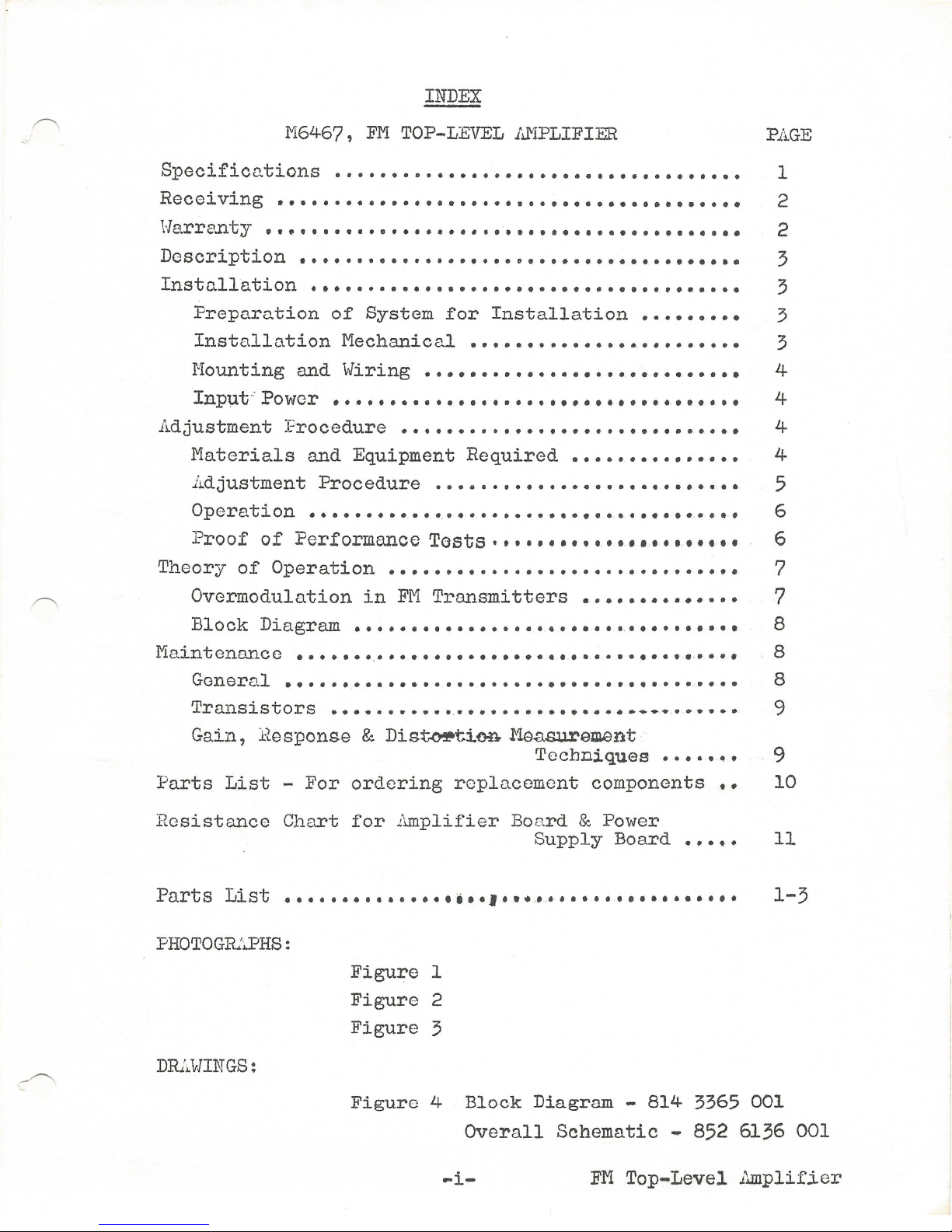
INDEX
1'16467,
FM
TOP-LEVEL
AMPLIFIER
PAGE
Specificn.tions
• • • • • • • • • • • • • • • • • • • • • • • •• • • • • • • • • • • • 1
Receiving
• . . . . . . . . . . . . . . . . . . . . . . . • • . • . . . . • • • • . . . • • 2
\~le
..
rre..nty
•.••.........•....•..
·• •• • •• • • • . • • • • • • . • • • • 2
Description••••·····•·•···•·•··•·••·••·•••••••••••
3
Instc.llation
. • . . . . . . . . . . . . . . . . . • . . . . • . . . . . . . • . . . . • 3
Preparation
of
System
for
Installation•··••••••
3
Installation
Mechanical
• •• • • • • •• • • • • • •.• • •• • • • • • 3
Mounting and
Wiring·••••····•·••·•···•••·•···••
4
Input·: Power • • • •• •• • • •• • ••• • •• • •• • • • • • •• •• • •• • •• 4
Adjustment
Procedure
• • • • • • • • • • • • • • • • • • • • • • • • • • • • • •
Materials
and Equipment
Required·•····•··••·••·
Adjustment
Procedure
········•······•···•··••·•·
Operation••····•···•~·•········•·••·•••••••·•••
Proof
of
Performance
Tests
••••
,
•••
,
•••
,
•,.,
, • • • •
Theory
of
Operation·••·••·•····•·•······•·•·····••
Overmodulation
in
Fi'1
Transmitters
• • • • • • • • • • • • • •
Block
Diagram
••••••••••••••••••••••••••••
• • • •• •
Main
t
enanc
c
•••••••
.
•••••••••••••••••
, • • • • • • • • • •-• • • •
General
••.....•..••..•........•••••••••..
• • • • • •
Transistors
••••·•·••·••••••••••••••·••·••••••••
Gain,
Besponse
&
Dis~tion.Me.asurement
Tocbniques
•••••••
Parts
List
-
For
ordering
replacement
components••
Resistance
Chart
for
1\.m.plifier Board & Power
Supply
Board • •• • •
Parts
List
••••••••••••••
, , , •1
•••
-
•.,
••••
• • • • • • •
•,
• •
PHOTOGRAPHS:
DRAWINGS:
Figure
1
Figure
2
Figure
3
4
4
5
6
6
7
7
8
8
8
9
9
10
11
1-3
Figure
4
Block
Diagram
-
814
3365
001
Overall
Schematic.
852 6136 001
..-i-
FH
Top-Level
i\mplifier
Steam Powered Radio.Com
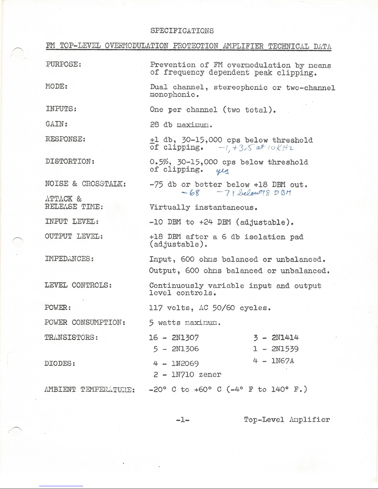
SPECIFICATIONS
FM
TOP-LEVEL
OVERMODULATION
PROTECTION
AMPLIFIER
TECHNICAL
DATA
PURPOSE:
MODE:
INPUTS:
GAIN:
RESPONSE:
DISTORTION:
NOISE
&
CROSSTALK:
.i\TTACK
&
RELEJ;.SE
TIME:
INPUT
LEVEL:
OUTPUT
LEVEL:
IMPED.illiCES:
LEVEL
CONTROLS:
POWER:
POWER
CONSUMPTION:
TRl..NSISTORS:
DIODES:
AMBIENT
TEr"IPER.i~TlDE:
Prevention
of
FM
overnodulation
by
oeans
of
frequency
dependent
peak
clipping.
Dual
channel,
stereophonic
or
two-channel
monophonic.
One
per
channel
(two
total).
28
db oaxir.1un.
+l
db,
30-15,000
cps
below
threshold
of
clipping.
- f
+3
,f
-
a.J-
to
e
t·
h
..
I
0.5%,
30-15,000
cps
below
threshold
of
clipping.
~
-75
db
or
better
below
+18
DBM
out.
-
08'
-
7f~
'i;
D(V1
Virtually
instantaneous.
-10
DBM
to
+24
DBM
(adjustable).
+18
DBM
after
a 6 db
isolation
pad
(adjustable).
Input,
600
olms
balanced
or
unbalanced.
Output,
600
ohos
balanced
or
unbalanced.
Continuously
variable
input
and
output
level
controls.
117
volts,
AC
50/60
cycles.
5
watts
naxinun.
16
-
2Nl307 3 -
2N1414
5 - 2N1306
1
-2Nl539
4 - 1N2069 4 -
1N67A
2
-1N710
zener
-20°
C
to
+60° C
(-4°
F
to
140°
F.)
-1-
Top-Level
JUJ.plifier

Steam Powered Radio.Com
SIZE:
SPECIFI
C.ATIONS
5¾"
x
19"
x
12".
Mounts
in
s,
tandard
191'
relay
cabinet.
WEIGHT:
25
lbs.
net
cubage
12.
FINISH:
CONTROLS:
TEST POINTS:
RECEIVING
45
lbs.
dowestic
pack.
Mediun
gloss
grey.
Each
channel:
Input
level,
output
level,
calibrate.
.i.'-
..
liwiter/operate
disable
switch
is
included
for
Proof
of
Perfornance
tests.
Adjust
level,
bias
adjust,
front
panel
test
points
are
provided.
ILIDediately
upon
receipt,
the
unit
should
be
carefully
unpacked
and
inspected
for
apparent
or
concealed
shipping
dru.1age.
In
case
of
danage
in
transportation
notify
the
delivering
carrier
at
once.
l,.fter
he
has
approved
the
dru1ago
report,
which
indicates
he
will
accept
your
billing
for
the
dru.iage,
order
new
parts
frou
Gates
Radio
Conpany,
Our
billing
of
these
parts
plus
transportation
expense
will
be
your
clain
to
the
trnnsportation
conpany.
W.ARRANTY
FM
Top-Level
is
covered
under
the
sto.ndnrd
Gates
Warranty,
a
copy
of
which
nay
be
had
on
request
fron
Gates
Radj_o
Conpany,
123
Haupshiro
Street,
Quincy,
Illinois
62301.
-2-
Top-Level
.Anplifier

Steam Powered Radio.Com
DESCRIPTION
r----.
The
Gates
FM
Top-Level
controls
high
frequency
peaks
which,
when
pre-eophasized
by
the
standard
FM
75
nicrosecond
curve,
would
cause
illegal
overnodulation
of
the
transnitter.
The
unit
is
a
dual
channel
device
that
can
be
operated
in
stereo
or
as
two
in-
dependent
single
channel
units
for
oonaural,
storecast,
or
tele-
vision
sound
applications.
The
awplifier,which
is
solid
state,
consists
of
a
regulated
power
supply
and
two
identical
anplifier
boards.
The
anplifier
section
contains
the
following:
an
input
anplifier
to
adjust
the
level
of
the
inconing
signal
and
FM
pre-
eophasis
filter
to
exactly
duplicate
the
signal
as
seen
by
the
transni
ttcr;
a
adjustable
clipper
which
acts
on
signals
in
excess
.
of
a
pre-set
level;
a
output
aoplifier
section
to
recover
filter
losses;
and
a
de-enphasis
filter
to
give
an
overall
nat
response
curve.
A drop-clown
panel
perEits
access
to
the
input
and
output;
level
controls,
calibrate
control
(clipping
level
adjust),
fuse,
and
operate
disable
switch.
This
switch
disables
the
clipper
for
Proof
of
Pcrfornance
tests.
Access
to
tho
top
and
botton
of
the
unit
is
ncconplishod
by
tho
use
of
1/4
turn
fasteners.
Input
o.nd
output
teroinations
are
nade
to
a
barrier
typo
terninal
strip
located
on
the
rear
of
tho
aIJ.plifier.
A
grounded
3-conductor
line
cord
is
supplied
with
the
unit.
INSTiJ.iLATI
ON
Preparation
of
Systeo
for
Installation
Prior
to
the
installation
of
the
Top-Level
it
is
necessary
to
check
with
sine
wave
and
adjust,
if
necessary,
the
opera.tion
of
tho
FM
nodulation
uonitor
to
insure
correct
flasher
calibration
with
tho
oodulation
noter.
Tho
channef
balance
in
a
stereo
systen
should
tlso
be
checked.
In
stereo
installations
the
audio
chain
should
bo
balanced
for
oquo..l
output
through
the
turntable
stereo
preanplifiors,
console
n.nd
liniter.
Installation
Mocha.nical
Tho
Top-Lovcl
should
electrically
feed
the
transnitter
after
the
peak
lini
tor.
It
is
rocoDDended
thnt
tho
Top-Level
be
insto.ll0d
at
the
trnnsnittor
sito
to
recover
losses
incurred
in
the
tele-
phone
pro
gr
on
lines.
Since
routine
adjustuent
is
unnccessc
.
ry,
a
transnittor
site
installation
is
satisfactory.
The
conventional
lir..iiter
nc.y
be
installed
either
at
tho
trnnsnitter
sito
or
o.t
the
studio.
Tho
FM
Top-Level
should
be
initially
installed
with
the
input
end
output
controls
nininWJ.
(countorclockwise).
Do
not
chnngo
calibrate
control.
Adjustuent
of
the
Top-Level
is
des-
cribed
in
the
section
titled
LDJUSTMENT
PROCEDURE.
-3- Top-Levol 1~1plificr
Steam Powered Radio.Com
Mounting
nnd
Wiring
The
unit
requires
5%"
of
panel
spac.c
in
a
s.t.andard
19''
r.elay
rack.
Input
and
output
toroinations
are
oade
at
the
barrier-typo
terninnl
strip
located
at
tho
renr
of
tho
unit.
The
various
in-
puts
and
outputs
nro
identified
on
the
rear
panol
and
µlso
on
the
schouatic
diagran.
Phase
relationships
have
been
uaintainod
with-
in
the
unit
with
the
input
and
output
phase
oarked
with
a
dot
on
the
barrier
strip
proper.
Us0
tho
clotted
ternino.l
for
tho
high
lead
of
the
audio
pair
and
proper
phQsing
will
bo
oo.intained.
Care
should
be
taken
to
toroinate
tho
shields
of
tho
input
and
output
cn.bling
at
one
end
only,
and
nn
appropriate
plo.ce
is
shown
on
tho
barrier
strip.
For
optinun
results
use
insulated
twisted
shielded
pcirs
such
as
Bolden
#8451
for
both
input
and
output
wir-
ing.
Individual
systeos
require
individual
ground
systeu
prac-
tices,
however,
avoid
ground
loops
for
bost
operation.
The
one
point
ground
systoo
is
nost
corn.10nly
usod
and
generally
offers
superior
results.
Ground
tho
oxtornal
ground
point
to
stntion
ground.
Tho
one
point
grounding
syster.1
requires
that
each
unit
of
an
audio
syston
have
its
01,·m
conductor
running
to
the
cannon
ground
point.
The
COLlilOn
point
should
be
conncctod
with
heavy
copper
strap
to
the
station
ground
and/or
oo..rth grc·und
to
give
the
systco
the
low-
est
possible
ground
reference.
Input
Power
In
order
to
cooply
with
recent
laws
of
sono
states
the
FM
Top-
Level
uses
a
three-prong
grounded
power
cord.
Tho
ground
pin
in
tho
AC
distribution
systeo
nust
bo
properly
grounded
for
proper
operations,or
hun
nay
bo
induced
into
the
anplifier.
ADJUSTMENT
FROCEDURE
After
tho
FM
Tcp--Levol
has
been
installed
in
the
rack,
calibration
and
acljustncnt
I.lay
be
perfornod.
The
conplete
procedure
outlined
below
is
for
[t
stereo
instri.llation.
idjusting
the
left
channel.
For
Donauro.l
inst2.llation
or
dunl
channel
inst3.llat:i,on,
follow
Stops
l
through
8.
1"!1:1.teriD.ls
an9-:Eguipnont
Roguircd
1.
Volt-om
_
mctor
such
ns
a
iS,i::.1pso.n
269
O]';l.
Tr:LpJ.irtJ:;.
#6-yJ.
2.,
Modulation
i:.loni
tor
instruction
book.
3.
Screwdriver.
4.
.12" Jur
..1
por
with
standnrcl
tip
t o
fit
test
points
on
tho
Top-Lovel.
-4-
Top-Level Aopllfior
Steam Powered Radio.Com
Adjustuent
Procedure
1.
2.
4.
5.
6.
7.
8.
10.
Controls
Settings
-
Check
to
Dake
sure
that
all
input
and
output
controls
are
fully
counter-clockwise.
Switch
the
0:2KB.1l,.T:S/DISABLE
switch
to
OPERATE
and
plug
the
line
cord
into
a
AC
receptacle.
Peak
Liniter
Operation
-
Play
a
nonaural
record
or
tape
with
the
conventional
peak
liuiter
opera.ting
in
the
stereo
node
where
used.
The
liniter
should
work
nornally,
linit-
ing
about
5
to
6
DB.
Set
the
VOI-I
to
read
approxiraately
10
volts
DC
and
plug
it
into
th
e l
eft
clipper
bias
test
points
located
on
the
left
side
of
the
inside
front
panel
behind
the
front
door.
The
white
ter:.:1
.
inal
is
positive
and
the
black
terwinal
is
neg-
ative.
(See
FIGURE
1).
Calibrate
Setting
-
(Factory
adjusted).
Adjust
the
left
C.A.LIBR.ATE
control
until
the
VOr-1
reads
3.5
volts
DC.
Input
Level
Adjustuent
-
With
the
VOM
still
plugged
in
the
left
test
points,
increase
the
left
input
control
until
the
VOI-1
neter
needle
just
begins
to
indicate
a
slight
re-
duction
in
voltage.
DO
NOT
INCREASE
THE
INFUT
CONTROL
BEYOND
THE
FOINT
OF
INDICATION.
Now
adjust
the
left
cal-
ibrate
control
until
the
VOM
reads
4.1
volts
DC.,
.Adjust
the
FM
11odulation
nonitor
flas
he
r
to
read
at
the
desired
level
of
raodulation.
Increase
the
left
channel
output
control
until
the
nodula-
tion
nonitor
flasher
just
indicates,
then
back
it
off
slightly.
For
i:ionaural
or
separate
dual
chann
el
installation
onit
Steps
9
through
12
and
go
to
Step
13.
For
stereo
install-
ations
repeat
Steps
1
through
7
for
the
right
ch
annel
and
then
go
on
to
Steps
10
through
13.
(See
FIGURE
2
).
Stereo
Channel
Balance
-
Connect
the
bottou
white
ADJUST
LEVEL
test
points
together
with
the
12"
jun.per.
(See
FIGURE
3).
Set
the
VOE
for
about
10
volts
AC
and
plug
the
neter
into
the
two
top
black
ADJUST
test
points.
With
the
progran
level
tost
tone
of
1
KC
fed
fron
the
console
(this
could
be
a
1
ICC
or
400
c;ycle
test
tone
fron
a
test
record
or
signal
generator),
adjust
the
right
output
of
the
Top-
Level
until
the
VOM
is
at
nininun
reading.
It
now
indi-
cates
that
the
levels
in
the
right
and
left
channels
are
equal
and
the
channels
are
balanced.
11.
Switch
the
VOM
to
the
lowest
practical
AC
voltage
scale
and
adjust
the
right
output
of
the
Top-Level
for
nininUlu
reading
again.
12.
Leave
tho
jUDper
and
ueter
in
place.
-S-
Tnn-T,A~T
A1 An-n1
'i
f''i
A"I"'
Steam Powered Radio.Com
..
13.
Ad,iust
for
optimum
;eerformance
-
Play
several
monophonic
records
of
the
type
program
material
normally
encountered
in
your
station's
operation,
observing
the
modulation
monitor
flasher.
Carefully
adjust
the
left
and
right
channels
alternately
(in
stareo
installations)
in
small
increments
until
tho
peak
flasher
seldom,
if
evor,
lights.
It
will
be
necessary
to
play
several
styles
or
types
of
records
normally
encountered
in
everyday
usage
to
set
the
correct
output
feed
to
tho
transmitter.
NOTE:
Because
sine
wave
testing
will
not
react
in
the
s'aiiie"mannor
as
musical
peaks,
it
is
necessary
to
observe
tho
flasher
and
udjust
the
output
level
until
sctisfactory
modulation
levels
are
maintained.
It
is
now
necessary
to
readjust
the
stereo
balance
in
stereo
installations
when a
suit-
able
setting
is
achieved
(Steps
9-12).
IMPORTANT
NOTICE!
It
is
very
important
that
tho
station
engineer
observe
the
modulation
monitor
flasher
for
a
period
of
two
or
three
hours
in
order
to
make
sure
that
the
output
level
is
o.t
the
correct
setting.
Since
this
varies
slightly
from
musical
selection
to
musical
selection,
this
adjust-
ment
and
observation
must
bo
made.
Typical
test
records
for
this
purpose
should
preferably
bo
muted
trumpets
2nd
cymbrtl
crashes,
triancle
nnd
other
percussion
effects.
Those
o.ro
good
sources
of
typical
problem
passages
which
mny
be
used
in
adjusting
the
FM
Top-Level.
Qperation
The
Gates
FM
Top-Level
is
a
device
which
clips
high
frequency
penks
that
exceed
the
pre-emphasis
curve.
In
stations
that
desire
to
clip
only
random
peak
signals
rather
than
trying
to
maintain
tho
absolute
maximum
of
modulations,
slightly
lower
settings
of
tho
output
control
will
be
nocessnry.
It
must
be
rememborod
that
when
the
FM
Top-Lovol
acts
on
these
high
fre-
quency
sign~ls,
it
effectively
clips
them
and
while
the
effect
is
not
noticoo
.
blo
in
the
form
of
distortion,
it
does
reduce
slightly
tho
overall
frequency
response
of
that
signal.
Proof
of
Pcrfo:c:mo.ncc
Tests
After
tho
unit
hc..s
boon
adjusted
o.nd
bc..lnnced
for
stereo
oper-
ation
or
monaural
oporQtion,
no
additional
operator
attention
is
necessary.
Whon
running
Proof
of
Performance
checks
the
clipper
section
of
tho
unit
can
be
effectively
disabled
by
switching
the
OPERATE/DISABLE
switch
to
the
DISABLE
position.
The
clipping
bias
is
raised
to
a
level
well
above
that
signal
used
in
tho
audio
Proof
of
Forformance
tests.
No
re-adjustments
are
neces-
sary
and
o.ftor
tho
Proof
has
beon
completed,
the
Fl'1
Top-Level
can
be
rcturnocl
to
normal
operation
by
switching
the
unit
back
to
OPERATE.
-6-
FM
Top-Lovel
Amplifier

Steam Powered Radio.Com
THEORY
OF
OFERATION
Ovormodulation
in
FM
Transmitters
FM
overmodulation
is
becoming
an
increo.singly
serious
problem
to
broadcasters
due
to
the
increasing
amounts
of
high
frequency
content
in
today's
program
mo.terial
as
the
result
of
improved
recording
techniques
and
equipment
combined
with
the
tendency
to
severely
pro-emphasis
highs
or
otherwise
girm:aick
recordings.
When
such
progrnm
material
is
itself
pre-emphasized
by
the
stand-
ard
FM
75
filicrosecond
curve
with
its
15
DB
boost
at
15
KC,
~
high
percentage
of
overmodula.tion
frequently
occurs.
Ideally
the
dis-
tribution
of
typicc.l
pee.ks
should
oxnctly
follow
the
conpliment-
ary
curve
to
the
FM
75
microsecond
curve
to
obtain
maximum modu-
lation.
It
has
been
shown
from
laboratory
tests
and
field
rs-
ports
tho..t
the
high
end
of
the
froquoncy
spectrum
is,
in
some
cases,
+10
DB
or
t1ore
greater
than
the
ideal.
When
o..
systefil
is
set
for
mediUD
frequency
modulation
level
of
50%
(50-3,000
cps)
a
typical
uncontrolled
high
frequency
pe1lk
can
cause
170%
modu-
la.tion.
Conventional
lit1itors
due
to
their
finite
attack
tiue
can
not
offectivoly
control
all
of
the
overmodulating
penks.
The
peak
limiter
soes
and
acts
upon
an
ontiroly
different
wave
forra
Ca
linenr
signal)
than
that
which
modulates
the
transraitter
(a
high
frequency
pre-emphasized
signal).
Modulation
t1onitors
have
inhoront
linitations
regarding
the
indi-
cation
of
high
frequency
pee~s.
Tho
modulation
monitor
t1cter
and
operated
flQshcr
devices
can
not
follow
such
peaks
duo
to
the
inertia
and
noter
ballastics.
Neon
flashers
may
operate
too
quickly
to
bo
detected
or
nay
fail
to
indicate
an
overt1odulo.ting
peak
regardless
of
height
if
its
duration
is
insufficient
to
chnrge
tho
associo.tod
RC
network
to
the
ionization
level
of
tho
neon
bulb.
Ovcrooc1ula.tion
cc.n
result
in
cross-channel
inter-
ference,
stereo
crosstalk,
2nd
distortion
of
transmitters
duo
to
bandpass
lir;1i
tc..tions
and
the
generation
of
spurious
signals.
The
FCC
rules
sto.to
that
nodulo.tion
peaks
should
lie
between
85
and
100%.
A good
rule
of
tho
thunb
to
use
in
cooplying
with
this
requironent
is
that
o.
peak
of
85%
should
be
reached
nt
least
a
half
a
dozen
tines
during
every
fifteen
minutes.
In
cases
of
n
loud
coonercinl
n
reduction
below
85%
is
pernitted.
If
nore
detailed
infornntion
is
required
on
tho
subject
of
FM
overnodu-
lation,
write
for
o.
copy
of
Gc..tes
Engineering
Report
-
"Prevent-
ing
FM
Ovornodulution".
Sond
request
to
Gates
Radio
Conpany,
123
H2..1:1:pshir0,
Quincy,
Illinois
62301.
-7-
FM
Top-Level
.Aoplifier
Steam Powered Radio.Com
Block
Diagrru:i
The
block
dingrnn
of
the
Gates
FM
Top-Lovel
is
shown
in
Figure
4.
Since
both
cho.m1.els
arc
tho
s8.Ilc,
only
one
will
be
described.
1
l1ho
constant
inpedance
nttonuo.tor
enables
the
input
to
accept
a
wide
range
of
signnl
lovels.
The
8.IJplifior
is
one
of
two
identicnl
solid
sto.to
anplifier
sections
de
signed
to
rocover
lossos
·
in
the
pre-ouphasis
ond
do-onpho.sis
filtors.
Tho
pro-onphasis
filter
is
o.n
LCR
conbination
which
follows
a
standard
curve
fron
30
to
15,000
cycles.
The
clipper
unit
consists
of
two
high
frequency
diodes
connected
in
a
bale.need
sorios
clipping
configur2..tion
with
a
variable
bio..s
which
allows
o.
clipping
level
to
be
adjusted
ovor
a wido
range
of
audio
signals.
For
proper
operation
4.1
volts
DC
is
reconnendcd.
Any
pre-onpho.sis
poruc
which
exceeds
o.
preset
lovol
will
bo
clippod
o.nd
only
tho.t
poo.k. Tho
rest
of
the
couplox
wo.vo
is
unnffectocl.
The
signal
is
then
o.nplified
by
the
second
anplifier
and
passod
through
o.
do-cnphc.sis
filter
which
is
the
exact
conpleuent
to
tho
pre-ouphasis
filter
up
to
15
KC.
Tho
signal
is
then
fed
to
the
output
transfornor,
6
DB
isolation
pad
nnd
attenuator.
When
the
FM
Top-Lovcl
is
properly
adjusted,
its
action
is
in-
audible
because
only
a
snall
porcentago
of
the
actual
wave
is
actE::d
upon
at
nny
tine.
Effects
will
bo
naskod
by
the
higher
level
low
frequency
cor.1ponents when
do-onph2.sizecl.
The
ear
is
also
relatively
insensitive
to
level
changes
at
high
frequencies.
Finally,
the
high
frequency
ho.rnonics
genoro.tec1
by
clipping
are
largely
ultrasonic
second
or
higher
ordor
haruonics
and
are
atten-
uated
by
tho
do-onphasis
filter.
MAINTENANCE
General
No
routine
naintonc:nce
of
the
FM
Top-Level
is
required
except
for
periodic
rer.iovo.l
of
dust
c.nd
dirt
with
o.
soft
brush.
A
check
of
tho
circuit
voltages
on
a
seni-aP~~ual
basis
will
£oro-
cast
i11pcnc1ing
problows.
Corto.in
resistors
on
tho
block
circuit
diagrau
o.ro nc..rl{ed
with
a
suffix
"A".
These
nay
bo
pnrn.llclod
with
a
resistor
with
o.
suffix
"B"
at
tho
fr:.ctory
for
conpcnsation.
Avera.go
readings
of
AC
and
DC
levels
nrc
shown
on
a
schenatic
diagran.
It
is
rccouncndcd
that
they
bo
chocked
with
tho
noter
which
will
bo
used
for
nainteno.nce
and
rocordod
for
future
refer-
ence
before
insto.llntion.
In
:c.nking
such
checks,
do
not
probe
tho
printed
circuit
bonrd
with
an
oxposod
nctnl
probe.
A
nouen-
tary
short
cnn
perno.nontly
dcnago
transistors.
Posi
ti
vc
ro..t:;hcr
them
ncgnti
VG
ground
is
oD.ployod
so
circuit
volt-
agcs
arc
rovorscd
fron
stondnrd
vccuun
tube
practicos
ns
is
tho
polnrity
of
tho
olcctrolytic
capacitors.
Obsorvo
those
polar-
ities
when
installing
nGw
cnpacitors
or
diodes.
-8-
FM
Top-Level
.Ar.lplificr

Steam Powered Radio.Com
Transistors
Direct
coupled
circuitry
will
allow
one
defective
transistor
to
affect
nost
or
all
of
the
circuit
voltages
in
that
section,
thorofor
o, when
troublo
occurs
in
such
circuitry,
all
transistors
should
bo
chocked
on
a
good
connorcial
transistor
tester.
NOTE
OF
CAUTION!!
1.
Do
not
rouovo
or
insert
transistcrs
with
the
POWER
ON!
2.
Do
not
probe
the
board
with
an
exposed
uotal
probe!
3.
Do
not
nnkc
ohnnotcr
roadings
with
transistors
in
tho
circuit!
4~
Avoid
tonporaturos
above
99°
C,
such
as
accidental
contc.ct
with
a
soldering
iron.
When
replacing
transistors
or
servicing,
check
to
see
that
the
transistors
are
properly
seated
in
their
sockets.
When
replacing
QlOl,
and
before
turning
on
the
power,
use
an
ohnnetcr
to
check
the
resistance
between
the
screw
nounting
and
the
netal
chassis
to
nako
certain
that
it
is
not
shorted
out.
On
all
voltage
readings
allow
at
least
10%
deviations
due
to
differences
in
nctors
and
vnric.tions
in
conponents.
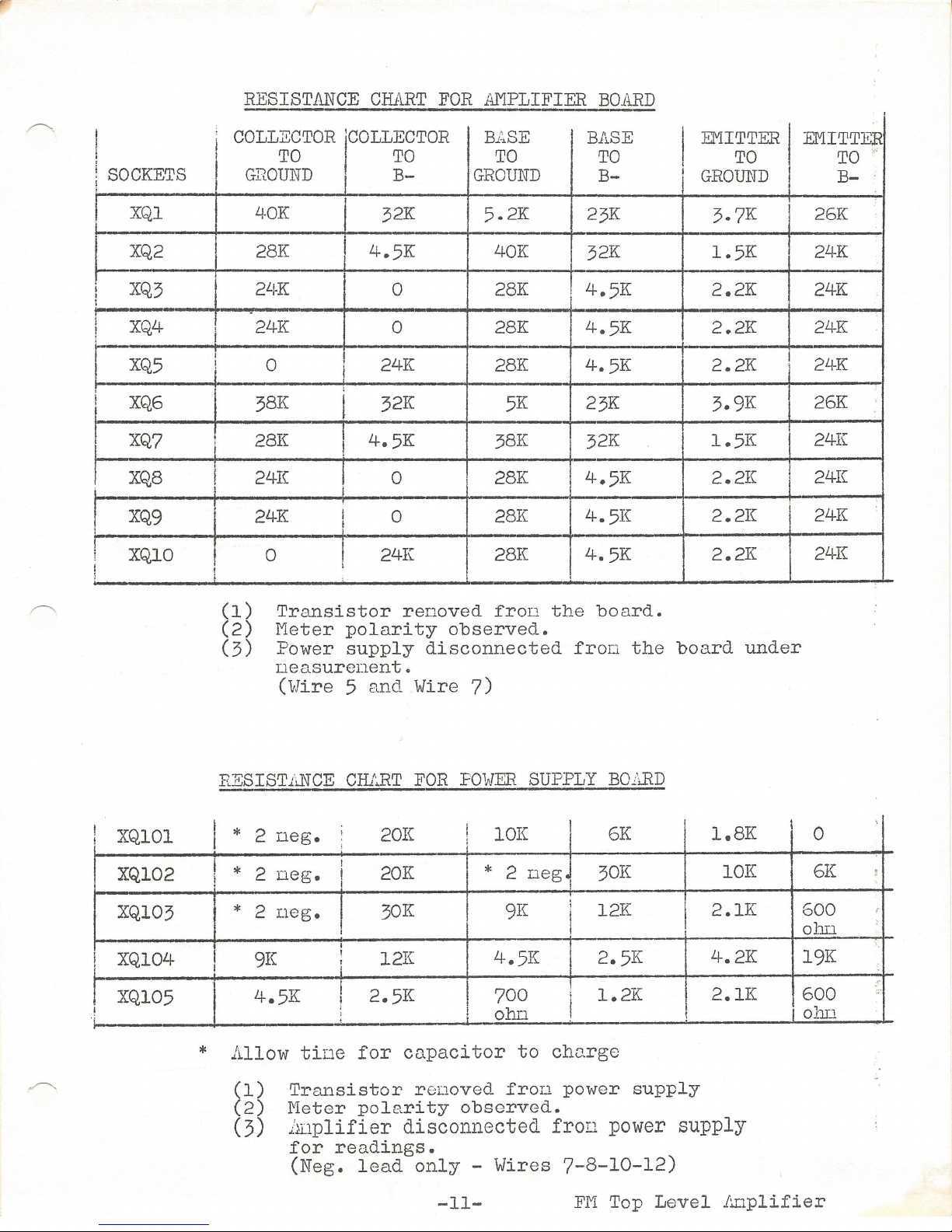
A
resistance
chart
is
shown
in
Figure
3
to
aid
in
troubleshooting.
All
transistors
nust
be
renoved
froTI
their
sockets
before
taking
resistance
:r.100.suronents,
and
do
not
remove
or
insert
transistors
with
tho
power
ONo
Gain,
Rosponsc
and
Distortion
Monsurorn:mt
Techniques
Becauso
of
tho
frequency
dopondent
nature
of
Top-Level,
certain
precautions
o.ro
nocossa,ry
to
obtain
noaningful
do.tn
with
regard
to
gain,
rosponso
and
distortion
readings.
Gain
-
Measure
go.in
ut
200
cps
which
is
on
the
flo.t
part
of
tho
pro-onphasis
curve.
To
neasuro
-
1.
Turn
all
input
and
output
controls
naxinun
clockwise.
2e
Feed
a
-10
DBM
signal
of
200
cps
at
600
ohns
into
tho
input
torninals.
3.
Tho
output
should
road
+18
DBM
into
a
600
ohn
load,
which
is
a
gain
of
28
DB.
Response
-Tho r o
sponso
readings
nust
be
taken
below
the
threshold
of
clipping
at
15
KC.
Therefore,
nnke
o.11
frequency
response
r.:.easurer.::.cnt
tests
with
a
-L~O
DB1'1
input.
Tho
output
level
will
be
approx-
inatcly
-12
DBM
if
tho
controls
arc
wide
open.
-9-
FM
Top-Level
.Anplifior
Steam Powered Radio.Com
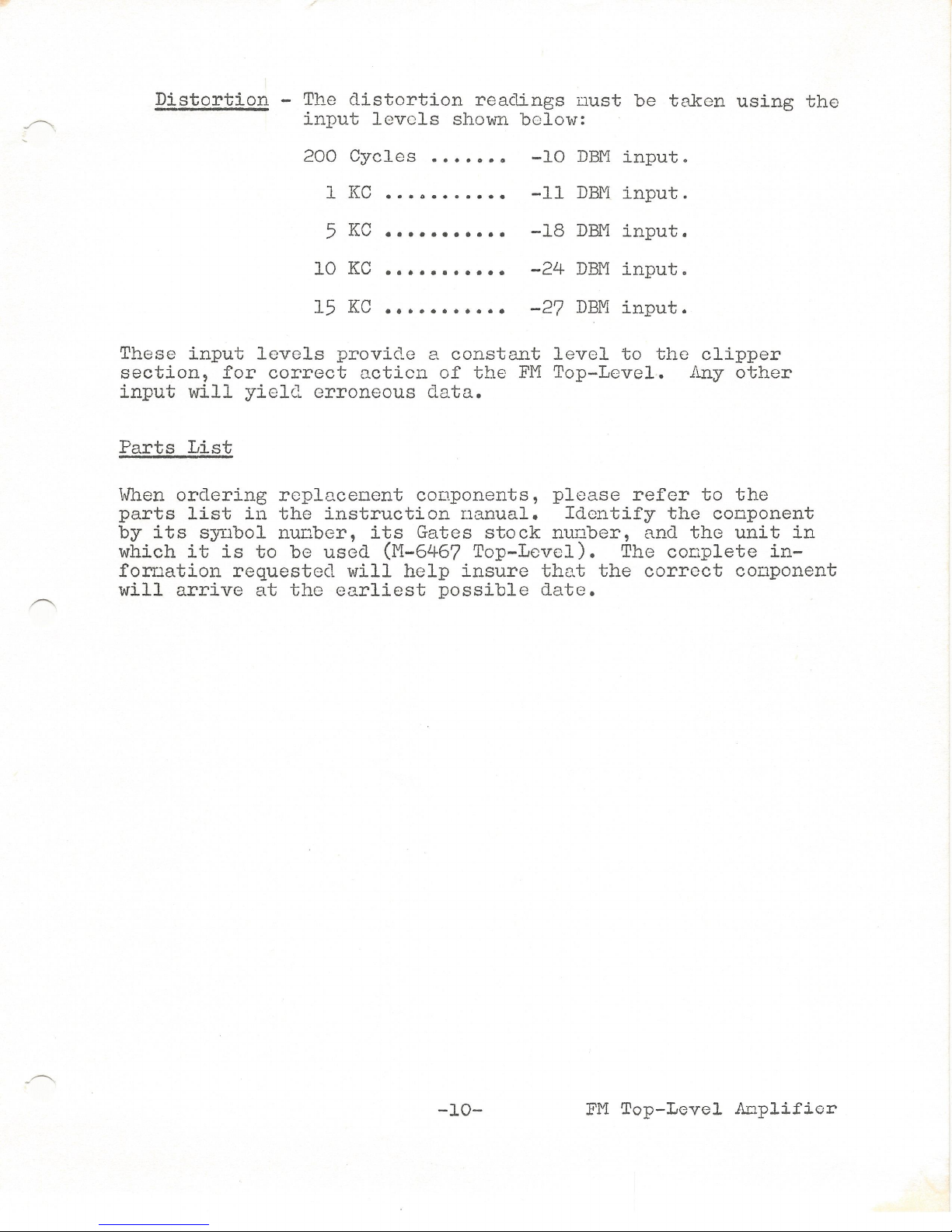
Distortion
-The
distortion
readings
uust
be
taken
using
tho
input
levels
shown
below:
200
Cycles
• • • • 0 •
ll
-10
DBM
input.
1
KC
• • • 0 • • • • • • •
-11
DBJVI
input.
5
KC
• • • • •• • • • • •
-18
DBJVI
input.
10
KC
• • • • • • • • • • •
-24
DBM
input.
15
KC
• •• • • • • • • • • -27
DBM
input.
These
input
levels
provide
a
constant
level
to
tho
clipper
section,
for
correct
ncticn
of
the
FJVI
Top-Level.
lmy
other
input
will
yield
erroneous
data.
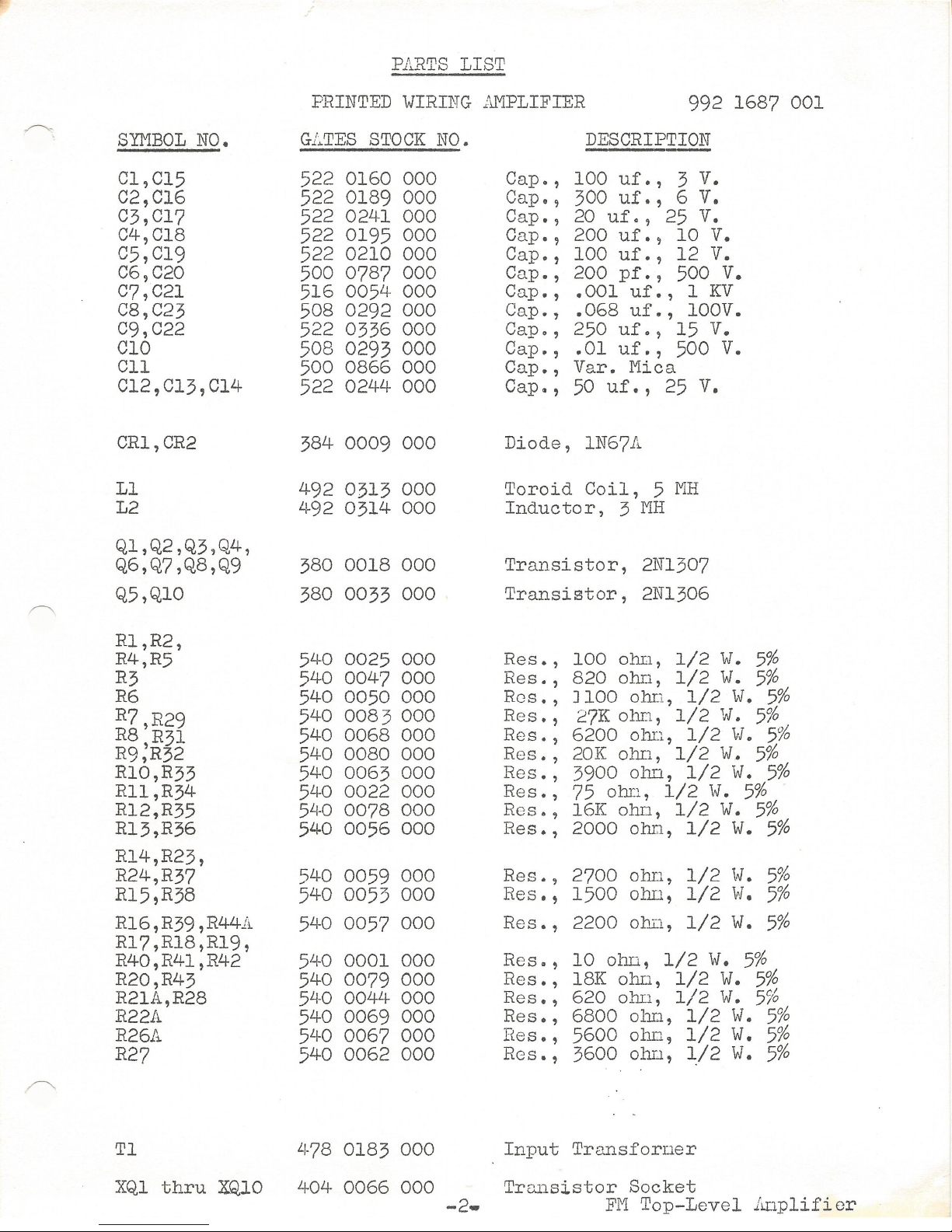
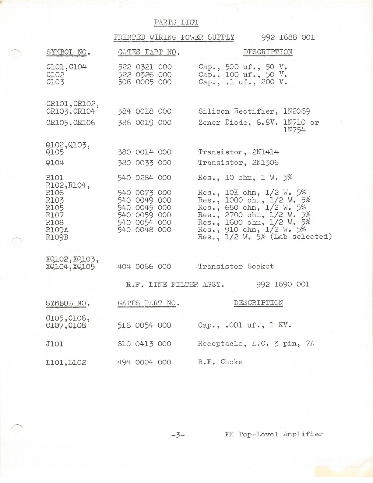
Parts
List
When
ordering
rcplncenent
conponents,
please
refer
to
the
parts
list
in
the
instruction
nanual.
Identify
the
conponent
by
its
synbol
nunber,
its
Gates
stock
nunber,
and
the
unit
in
which
it
is
to
be
used
(M-6467
Top-Level).
The
conplete
in-
forriation
requested
will
help
insure
that
the
correct
conponent
will
arrive
at
the
earliest
possible
date.
-10-
FM
Top-Level
Ar:lplifier
Steam Powered Radio.Com
I
~
!
SOCKETS
i
I
XQl
L.
~XQ,2
t
XQ3
1
XQ4
XQ5
XQ6
XQ7
XQ8
I
XQ9
l
I
XQlO
f
I
;
XQlOl
XQ102
XQ103
XQ104
XQ105
I
i
'
i
I
!
I
I
I
!
!
i
I
!
!
I
I
RESISTANCE
CHART
FOR
AMPLIFIER
BOARD
COLLECTOR
'COLLECTOR
BL.SE
BASE
TO
TO
TO
TO
GROUND
B-
GROUND
B-
40K
32K
5.2K
23K
-
28K
4.5K
40K
32K
24K
0
28K
4.5K
-
24K
0
28K
4.5K
-
0 I
I
24K
28K
4.5K
38K
I
32K
5K
23K
28K
I
4.5K
38K
32K
24K
I 0
28K
4.5K
I -
I
24K
I 0
28K
4.5K
t
0 I
24K 28K
4.5K
(1)
Transistor
renoved
froD
the
board.
(2)
Meter
polarity
observed.
I
EMITTER
TO
I
GROUND
3.7K
I
I
1.5K
'
2.2K
-
2.2K
-
2.2K
I
3.9K
1.5K
2.2K
2.2K
2.2K
(3)
Power
supply
disconnected
fron
the
board
under
neasurenent.
(Wire
5
and
Wire
7)
RESIST.ii.NCE
CHLRT
FOR
POWER
SUPPLY
BOARD
* 2
neg.
'
20K
lOK
6K
1.8K
i
!
i * 2
neg,
30K
lOK
* 2
neg.
I
20K
I I
* 2
neg.
I
30K
9K
; 12K
2.lK
I
I
9K
! 12K
4.5K
2.5K
4.2K
f
I
I
4.5K
I
2.5K
700 I
1.2K
2.lK
I l
ohn
'
-
*
Allow
tine
for
capacitor
to
charge
(1)
Transistor
renoved
fron
power
supply
(2)
Meter
polarity
observed.
(3)
hnplifier
disconnected
fron
power supply
for
readings.
(Neg.
lead
only
-
Wires
7-8-10-12)
EMITTER
TO
'
B-
26K
2LJ-K
-
24K
24K
24K
26K
24K
24K
24K
24K
0
6K
1
.
600 i
ohr.1
'·
19K
,
600
oh11
-11-
FM
Top
Level
1:..wplifier

Steam Powered Radio.Com
Synbol
No.
AlOl
ATl
,liT2,
AT5,AT6
.A.T3,li.T4
FlOl
Jl,J3,
J6,J8
J2,J4,
J5,J7
QlOl
R25,R45
Sl
T2,T3,
T4,T5
TlOl
TBl
XF101
XQlOl
,,-------..
.
8/24/65
P.ll.RTS
LIST
994
6467
CABINET
PARTS
Gates
Stock
No.
406
0355
000
554
0278 000
992
1689
001
398
0017
000
612
0312
000
612
0311
000
380
0016
000
550
0029
000
604
0302
000
478
0265
000
Li-72
0099
000
614
0036
000
402
0023
000
404
0136
000
-1-
Description
Pilot
Light,
125v.
Attenuator,
600
ohns
"T"
Pad
Output
Pad,
6
DB
ttH"
Pad
Fuse,
1
anp.
250V.
Test
Point
Jack,
White
Test
Point
Jack,
Black
Transistor,
2Nl539
Potentioneter,
lOK
ohLl,
2W.
Slide
Switch,
DPDT
Output
Transforser
Power
Transforner
Terninal
Board
Fuseholder
Transistor
Socket
FM
Top-Level
Anplifier
Steam Powered Radio.Com
SYMBOL
NO.
Cl,Cl5
02,Cl6
03,017
04,018
05,019
06,020
c7,c21
C8,C23
09,022
010
Cll
012,013,c14
CR1,CR2
Ll
L2
Ql,Q2,Q3,Q4,
Q6,Q7,Q8,Q9
Q5,Ql0
Rl,R2,
R4,R5
R3
R6
R7,R29
RS
R31
R9;R32
Rl0,R33
Rll,R34
Rl2,R35
Rl3,R36
Rl4,R23,
R24,R37
Rl5,R38
Rl6,R39,R44A
Rl7,Rl8,Rl9,
R40,R41,R42
R20,R43
R21A,R28
R22A
R26A
R27
Tl
PARTS
LIST
PRINTED
WIRING
AMPLIFIER
992
1687
001
G.LTES
STOCK
NO.
522
0160
000
522
0189
000
522
0241
000
522
0195
000
522
0210
000
500
0787
000
516
005LJ-
000
508
0292
000
522
0336
000
508 0293
000
500
0866
000
522
0244
000
384
0009
000
492
0313
000
492
0314
000
380
0018
000
380
0033
000
540
0025
000
540
0047
000
540
0050
000
540
0083
000
540
0068
000
540
0080
000
540
0063
000
540
0022
000
5LJ-O
0078
000
540
0056
000
540
0059
000
540
0053
000
540
0057
000
540
0001
000
540
0079
000
5LJ-O
0044
000
540
0069
000
540
0067
000
540
0062
000
LJ-78
0183
000
DESCRIPTION
-
Cap.,
100
uf.,
3
V.
Cap.,
300
uf.,
6
V.
Cap.,
20
uf.,
25
V.
Gap.,
200
uf.,
10
V.
Cap.,
100
uf.,
12
V.
Cap.,
200
pf.,
500
V.
Cap.,
.001
uf.,
1
KY
Cap.,
.068
uf.,
lOOV.
Cap.,
250
uf.,
15
V.
Cap.,
.01
uf.,
500
V.
Cap.
,
Var.
Mica
Cap~, 50
uf.,
25
V.
Diode,
1N67A
Toroid
Coil,
5
l'1H
Inductor,
3
l:'IH
Transistor,
2Nl307
Transistor,
2Nl306
Res.
,
100
olm,
1/2
W.
5%
Res.,
820
ohn,
1/2
W.
5%
Ros.
, J
100
ohn,
1/2
W.
5%
Res.,
27K
ohr:1,
1/2
W.
5%
Res.
,
6200
ohn,
1/2
W.
5%
Res.,
20K
ohn,
1/2
W.
5%
Res.,
3900
ohn,
1/2
W.
5%
Res.,
75
ohn,
1/2
W.
5%
Res.,
16K
ohn,
1/2
W.
5%
Res.,
2000
ohr1,
1/2
W.
5%
Res.
,
2700
oblJ.,
1/2
W.
5%
Res.,
1500
ohD,
1/2
w.
5%
Res.,
2200
o:bi1,
1/2
W.
5%
Res.,
10
ohn,
1/2
w.
5%
Res.,
18K ohD,
1/2
W.
5%
Res.,
620
ohn,
1/2
W.
5%
Res.,
6800
ohn,
1/2
W.
5%
Res.,
5600
olm,
1/2
W.
5%
RGs.,
3600
ohn,
1/2
W.
5%
Input
Transforner
XQl
thru
XQlO
404
0066
000
Transistor
Socket
-2-
FI'1
Top-Level
lmplifier
Steam Powered Radio.Com
SYMBOL
NO.
Cl01,Cl04
Cl02
Cl03
CR101,CR102,
CR103,CR104
CR105,CR106
Ql02,Ql03,
Ql05
Ql04
RlOl
Rl02,Rl04,
Rl06
Rl03
Rl05
Rl07
Rl08
Rl09A
Rl09B
XQ102,XQ,103,
XQ104,XQ105
SYl"lBOL
NO.
C105,Cl06,
Cl07,Cl08
JlOl
L101,L102
PARTS
LIST
PRINTED
WIRING
POWER
SUPPLY
992
1688
001
DESCRIPTION
G.LTES
PART
NO.
522
0321
000
522
0326
000
506
0005
000
384
0018
000
386
0019
000
380
0014
000
380
0033
000
540
0284
000
540
007.3
000
540
0049
000
540
0045
000
540
0059
000
540
0054
000
540
0048
000
4QL~
0066
000
Cnp.,
500
uf.,
50
V.
Cap.,
100
uf.,
50
v.
Cap. ,
.1
uf.
, 200
V.
Silicon
Rectifier,
1N2069
Zener
Diode,
6.8V.
1N710
or
1N754
Transistor,
2Nl414
Transistor,
2Nl306
Res.
,
10
o1:lI.l,
1
W.
5%
Res.,
lOK
olm,
1/2
W.
5%
Res.,
1000
01:!I.l,
1/2
w.
5%
Res.,
680
ohn,
1/2
W.
5%
Res.,
2700
ohn,
1/2
W.
5%
Res.,
1600
ohrc,
1/2
W.
5%
Res.,
910
ohn,
1/2
W.
5%
Res.,
1/2
w.
5%
(Lab
selected)
Transistor
Socket
R.]1• LINE FILTER
ASSY.
992
1690
001
GATES
F..::..RT
NO.
516
0054
000
610
0413
000
494
0004
000
-3-
DEBCRIPTION
Cap.,
.001
uf.,
1
KV.
Receptacle,
A.C.
3
pin,
7A
R.F.
Choke
FM
Top-Level
.i'..nplifier

Steam Powered Radio.Com
.,,,-----..
.
,,--....
.

Steam Powered Radio.Com
LOSS
200rv
I
KC
5
/\C
10
KC
ft;
KC
.)
) )
[
2DB@l5J<C
INPVT
INPIJi
PRE•
CL.IP-
TERM.
OVTPVT
0£-
ouTPVT
OUTPVT
PRE'-
EMP.
0
+-
I
+8
+It
+17
PADS
AMP.
EMP.
PER
PAD
AMP.
EMP.
X.FMR.
PADS
+ODBM {
[:>>-
~I~
I
~~-~--;
l'"'o'
:¥
INPUT
Le:
v.
I...OSS
L£'1.
6AtN
I..G.V,
LOSS
1..£\/,
-10
-5
-15
+
38
+23
-18
..,..5
-,,
,,
-16
..
+22
-17
t5
-
)8
"
-23
II
t-15
-JO
♦
s
-24-
,,
-29
"
+ 9
-+
+5
-27
.,
-32
,,
+6
-I
+S"
INPUT
AND
OUTPUT
CONTROLS
SET
FOR
O
ATT£NUATION.
-1.
I V
D.
C.
LOSS
L£\/.
-I
..,..
4
"
+4
II +4-
II
+
+
I/
+-4
FIGURE
4
LOSS
LEI/.
G-AIN
•,,:
..
~
-
,a
-/4
+4()
,,
-/4
II
,,
-/'1-
II
.,
-I
4-
,,
II
-
/4-
,,
L.
E.
"·
LOSS
LEV.
£..OSS
L.f:V,
LOSS
+26
-I
+25
• I
+24
-G
+2G
-2
+2+-
,,
+23
II
+26
-9
+17
II
+I~
I
I
t2(p
-15
+ II
II
+JO
If
+2b
-18
+-8
II
+7
II
BLOCK DIAGRAM (
SIGNAL
LEVEL
ANALYSIS
FM
TOP
LE\J £ L
8Jq,.
-3
3c;,5
-oo,
0
LE
v.
~,8
+-
/7
+/0
.,..
't
+-
l
Table of contents
Other Gates Amplifier manuals


