Gates M6108A User manual

M6108A
TRANSISTOR
MONITOR
AMPLIFIER
9
INSTRUCTION
BOOK
IB
#888
0921
001
GATES
RADIO
COMPANY
•
QUINCY,
ILLINOIS
•
62301
•
U.S.A.
A
division
of
Harris-Intertype
Corporation
.
I
■
■1
o
O

TECHNICAL
DATA
Gain:
Output
Impedance:
1.2
o ms,
approximately.
o
Maximum
Input
Level:
Frequency
Response
:
0
dbm.
Maximum
Output
Level
:
+
59
into
8
o ms
(8
watts).
Harmonic
Distortion:
Maximum
Operating
Ambient
Temperature:
F.)
C.
F.)
0.
Intermodulation
Distortion:
Power
Requirements:
117
Volts
at
50/60
cps.
,
18
watts.
Transistors
:
Noise
Level:
Rectifiers:
Source
Impedances:
(silicon)
4
X5A2
o
Finis :
C
Input
Impedances:
Mounting:
Load
Impedances:
Size
:
deep,
8-1/2
”
long.
Weig t
:
4
lbs
.,
net.
7
lbs.
,
packed.
Cubage
:
0.9
cu.
ft.,
Icmestic
pack.
DESCRIPTION
a
trails-^
o
-1-
+
1.0
db
from
20
to
20,000
cps
@
normal
output
level.
Under
1,0%
from
50
to
15,000
cps
@
+
58
dbm
output
(6
watts).
Under
1.0%
from
50
to
15,000
cps
@
+
59
dbm
output
(8
watts).
55
db
(matc ing
600
o m).
59
db
min.
(bridging
6,000
o m)
Under
1.0%
at
+
58
dbm
equivalent
sine
wave
power
output,
using
40
and
7000
cps
mixed
4:1.
-
85
db
below
rated
output
level
(+
59
dbm).
600
o ms
matc ing
input,
balanced
(transformer
input).
6,000
o ms
,
bridging
input,
balanced
(bridging
pad
and
transformer
input).
Two
key ole
slots,
rubber
bumpers
on
bottom,
permanent
or
movable
mounting,
in
any
position.
2
1
2
Lig t
grey
cover,
flat
black- eat
sink
c assis.
2N1414
2N214
2N1185
2N1225
2N5614
600
o ms
for
600
o ms
matc ing
input.
150/600
for
6000
to
10,000
o m
bridging
input.
1
2
(151°
5-1/4"
ig ,
4-5/8"
(185°
55°
Maximum
Storage
Ambient
Temperature:
85°
4
to
16
o ms
(8
o ms
nominal),
un
balanced
(transformerless
output,
isolated
from
AC
ground
by
power
transformer).
f e
M6108A
:
Monit^j?
Amplifier
is
istorized,
self-contained
amplifier
de
signed
for
use
in
broadcasting,
record
ing,
and
general
sound
reinforcement
applications.
Special
tec niques
ave
been
employed
to
obtain
reliability,
low
distortion,
and
good
temperature
sta
bility.
T e
amplifier
can
be
mounted
in
any
position
and
does
not
require
ventil
ation
w en
andling
8
watts
of
program
material.
T e
input,
power,
output
con
nections,
fuse
and
input
level
control
are
mounted
on
end
panels
of
t e
c assis.

INSTALLATION
MOUNTING
INPUT
CONNECTIONS
AMPLIFIER
PARALLELING
POWER
CONNECTIONS
I
2
3
4
5 6
7
0
GND.
Fi s.
1
NOTE
67
3
I
4
6000-n.
Fig.
2
OUTPUT
CONNECTIONS
M6108
MONITOR
AMPLIFIER
-2-
0
T e
amplifier
as
been
provided
wit
two
key ole
slots
for
#8
screws
for
fixed
or
permanent
mounting.
In
t e
event
t at
a
preamplifier
driver
is
used
requiring
a
minimum
load
of
10,000
o ms,
a
2200
o m
resistor
may
be
added
at
eac
bridging
input
terminal.
Wit
t is
c ange,
1.5
volts
input
wil]
be
required
for
full
output.
W ile
t e
amplifier
can
andle
a
contin
uous
8
watts
of
program
material,
CAUTIC
s ould
be
exercised
during
full
power
sine
wave
testing
to
avoid
exceeding
t e
t ermal
capabilities
of
t e
c assis
eat
sink.
During
t ese
tests
it
is
recommer
ded
t at
a
duty
cycle
of
30
seconds
on
t
5
minutes
off
be
used
to
allow
eat
buil
up
to
dissipate.
Provisions
are
made
for
c anging
from
600
o m
matc ing
to
6,000
o m
bridging
on
t e
input
terminal
strip.
Fig.
1
s ows
t e
connection
for
600
o ms.
Fig.
2
s ows
t e
connection
for
6,000
o m
bridging.
It
is
not
recommended
t at
amplifiers
of
t is
type
be
paralleled
at
t eir
outputs
to
obtain
ig er
power.
W ere
more
pow
er
is
required
t an
can
be
supplied
by
one
amplifier,
t e
speaker
load
s ould
be
divided
between
several
amplifiers
w ic
ave
t eir
inputs
bridged
across
t e
common
signal
source.
Output
connections
are
made
to
t e
two
lug
terminal
strip
on
t e
end
plate
of
t e
c assis.
Groups
of
speakers
may
be
driven
wit
t is
amplifier;
connected
in
series,
parallel,
or
series
parallel;
but
t e
combined
impedance
s ould
not
be
less
t an
4
o ms.
Wit
an
impedance
of
more
t an
12
o ms,
t e
amplifier
will
not
be
able
to
deliver
full
output
power.
Speaker
matc ing
transformers
permit
t e
paralleling
of
a
number
.of
speakers
,
de
pending
on
t e
unit
required.
Gates-
.'
Part
No.
480
0005
000
transformer.-:
is.x"
available,
aving
a
primary
of.
48
.
o ms
and
a
secondary
of
8
o ms
for
matc ing
purposes
.
In
wiring
speaker
loads
it
s ould
be
re
membered
t at
8
watts
at
8
o ms
repre
sents
1
ampere
of
audio
current.
T e
recommended
use
of
No.
16
gauge
twisted
and
s ielded
wire
will
prevent
power
losses
and
possible
interaction
of
cir
cuits.
4
5
.JUMPER
4
a
y
f
I
117
volts
A.C.,
50/60
cycles
is
supplied
t ru
t e
power
cord
and
power
plug
on
t
c assis
end
plate.
A
power
switc
is
no
required
due
to
t e
low
power
consumptic
and
eat
dissipation.

THEORY
OF
OPERATION
When,
he
Q5
L
I
02
Q6
Q4
Q7
•
'1
T2
FI
OS
C9
-3-
CIO
R2
PARTS
LOCATION
M6I08
TRANSISTOR
MONITOR
AMPLIFIER
.1
General
feedback
loops
are
employed
in
t e
amplifier
including
R5,
R19,
02,
04,
and
05•
02
and
04
provide
ig
frequency
feedback
w ile
05
supplies
positive
feed
back
from
t e
output
to
t e
collector
circuit
of
Q2
to
increase
t e
signal
andling
capacity
of
t is
stage.
C7
--------
UNDERSIDE
~~~
-------
PRINTED
BOARD
03
T ermistor
R4
compensates
for
variations
in
t e
amplifier
bias
due
to
temperature
c anges.
C oke
LI
renders
t e
amplifier
insensitive
to
c anges
in
capacity
across
t e
output
leads.
T e
power
supply
is
a
conventional
full
wave
bridge
rectifier
wit
filter
capacitor
circuit.
>
T e
amplifier
is
driven
by
an
input
transformer
w ic
provides
for
isolation
W
and
matc ing
functions
in
t e
primary
by
means
of
split
windings
and
resistive
pads.
T e
input
level
control
provides
a
constant
load
to
t e
input
transformer
secondary
w ile
furnis ing
a
gain
con-
.
trol
function.
Transistor
QI
operates
as
an
emitter
follower
and
provides
im-
oedance
matc ing
from
t e
input
to
t e
oltage
amplifier,
Q2.
Note
t at
Q2
is
t e
only
stage
w ic
as
voltage
gain.
A
ig
frequency
transistor
is
used
at
t is
point
to
improve
stability.
T e
output
stages
of
t e
amplifier
operate
Class
B,
and
are
arranged
in
t e
circuit
configuration
known
as
"single
ended
pus -pull"
or
a
'followed
emitter
follow
er".
T e
upper
and
lower
units
are
in
series
across
t e
power
supply,
and
t e
load
is
connected
at
t eir
junction.
W en
t e
signal
at
t e
collector
of
Q2
goes
negative;
Q5,
Q5,
and
Q7
conduct;
since
t ey
are
all
PNP
types.
signal
goes
positive;
Q4,
Q6,
and
Q8
all
conduct;
since
Q4
is
an
NPN
type.
T us,
t e
full
signal
appears
at
t e
junction
.point.
Q3,
Q5?
Q7»
and
Q6,
Q8
are
con
nected
in
a
compound
or
"Darlington"
configuration,
a
connection
w ic
provi
r
des
extremely
ig
current
gain,
and
im
proves
linearity
at
ig
signal
levels.
’
-J
-A
|
J
_
-
!
--
■'
•
■
>
W<r
a
__
it
■.

■4
16
‘
T7
17
C2
XQI
’
INPUT
OUTPUT
T
B
'
I
,
(7.0
4
16
BLU
+
[20/50
<r
T0i
0.9
1.0
YEL
4,
o
RED
5
GROUND
8RNZ
0.7
1.0
0.9
ui
4
4
co
I
I
I
II
Q
CBI
D
—
*
IA
-33V.
DC
•■•
‘
‘
Si
•
+
o
2
3
EXTERNAL
CONTROL
CONNECTS
TO
TERMINALS
6,I(ARM)B7
x
o
<
R5
56K
R4
T
50K
y
25°C
R6
390
R7
I0K
C5
25/25
4:
+
CRI
X5A2
CR3
QC5A;
C4
.0005
C3
X02
'
^r2NI225'
CR2-
w
X5Ai
CR4
X5A2.
RII
390
►
RIO
•
100
R8
IK
R9
7.5
K
C9
1000/50
X03
2NI4I4
XQ4
2N2I4
RI2
470
R
15
470
XQ5
?NH6i
RI3
51
RI6
51
XQ7
2N36I4
XQ8
2N36I4
SCHEMATIC
M6I08
A
TRANSISTOR
MONITOR
AMPLIFIER
RI7
l,IW
UJ
o
z
<
a:
o
R2
,560
R3
I30K-L-
2NI4I4
x
70
------
C6
-rlOO/3
+
RI9
47K
LI
5uh
+
T
T8
3
28
V.
AC
XQ6
2NII83
T1
478-0187-000
GRN.
<
RI4
S
IJW
“
C7
1000/
85
r£HH
C|
5P/j
5
A
>
RI8
e
22
I
C8
-r
25
200V
I.
ALL
CAPACITORS
IN
MFD,
WITH
D.C.W.-V
,
EXCEPT
WHERE
NOTED.
2
ALL
RESISTORS
I/2W.,
5%
EXCEPT*
I
%
,
AND
WHERE
NOTED.
3.0
DESIGNATES
BOARD
LUG
CONNECTIONS.
4
D
C
VOLTAGES
MEASURED
AGAINST
B+,
WITH
20K-n.
VOLT
METER
,
AT
4
38
08M
OUTPUT.
5.
(
R.M.S.SIGNAL
VOLTAGES
AT
IKC»-
15
DBM
WPUT,
(600^x.
+
38DBM
OUTPUT
*•.05

MAINTENANCE
PREVENTIVE
MAINTENANCE
2.
1.
2.
4.
5.
5.
6.
o
7.
8.
1.
PRINTED
CHASSIS
COMPONENT
REPLACEMENT
CHECKING
COMPONENTS
1.
-5-
T e
condition
of
t e
power
supply
can,
be
most
readily
c ecked
by
measuring
Voltages
may
be
c ecked
wit
Q5,
Q6,
Q?
and
Q8
removed,
provided
t at
t e
speaker
load
is
disconnected.
Do
not
remove
or
insert
transistors
wit
t e
power
on.
W en
servicing
t e
amplifier,
t e
follow
ing
points
s ould
be
observed:
C eck
t e
power
amplifier
supply
voltage
at
t e
collector
of
Q5
or
Q7-
On
t e
power
transistors,
suc
as
t e
2N1183
and
2N?614
,
t e
collector
is
con
nected
to
t e
case.
T e
components
s ould
be
carefully
c eck
ed
by
measuring
circuit
voltages
and
res
istances
before
attempting
to
remove
one
of
t e
leads
from
t e
printed
c assis.
Extreme
care
must
be
exercised
in
remov
ing
t e
lead
to
prevent
damage
to
t e
board
or
conductors.
T is
operation
s ould
not
be
considered
unless
it
is
t e
only
way
t e
component
can
be
c ecked.
Circuit
voltages
are
reversed
from
standard
vacuum
tube
practice,
as
is
t e
polarity
of
all
electrolytic
capacitors.
Do
not
probe
t e
printed
board
wit
a
metal
probe
wit
t e
power
on.
T e
location
of
t e
positive
end
of
eac
electrolytic
capacitor
is
indicated
by
t e
w ite
dot
marked
on
top
of
t e
circuit
board.
T e
M6108
Monitor
Amplifier
is
designed
for
long,
trouble-free
service..
However,
as
wit
all
ig
quality
electronic
equip
ment,
a
regular
program
of
inspection
s ould
be
followed.
T ese
points
s ould
be
covered:
W en
replacing
eit er
Q7
or
Q8»
and
before
turning
on
t e
power,
c eck
wit
an
o m-meter
between
transistor
case
and
c assis
to
make
certain
t at
a
s ort
circuit
does
not
exist.
Note
t at
insulating
was ers
are
placed
under
t e
transistors
to
provide
insulation.
Remove
dust
w ic
collects
on
t e
printed
board
or
in
t e
ousing,
wit
a
soft
brus .
It
is
recommended
t at
w en
t e
ampli
fier
is
first
placed
in
operation,
t at
D.C.
voltages
be
measured
wit
t e
same
voltmeter
t at
will
be
used
for
mainten
ance
and
troubles ooting,
and
t an
t ese
readings
be
recorded
on
t e
amplifier
sc ematic.
T e
speaker
bus
and
B-
volt
ages
s ould
be
recorded
wit
an
wit out
signal,
SERVICING
t e
D.C.
voltage
between
t e
c assis
and
t e
case
of
output
transistor
Q8.
(One
/-x
of
t e
two
power
transistors
mounted
on
'
—
'
t e
end
of
t e
c assis).
T is
voltage
will
be
muc
ig er
or
lower
t an
nor
mal
if
trouble
is
present
in
t e
power
amplifier.
If
one
lead
must
be
removed
wit out
dam
age
to
t e
component,
apply
a
well
clean
ed
and
tinned
25
to
60
watt
iron
to
t e
fillet
adjacent
to
t e
lead.
Wit
small
long
nose
pliers
or
t in
screwdriver,
pry
t e
folded
portion
of
t e
lead
in
line
C eck
t e
speaker
bus
voltage
,
w ic
appears
at
t e
collectors,
or
cases
of
Q6
and
Q8.
3.
Circuit
resistances
s ould
be
meas
ured
only
after
removing
t e
associated
transistor
or
transistors,
to
prevent
damage
due
to
o m-meter
battery
voltage.

s arp
cutters.
pliers
B
A
RESOLDERING
THE
COMPONENT
LEAD
2.
I
FdLg.
6
-
Installing
New
Component
Fig.
3
-
Cleaning
Holes
pliers
Fig.
4
-
Removing
Lead
REPLACING
COMPONENTS
3<
-6-
£
■M
fold
&
clip
ere
F
<
/
3
iron
tip
clip
leads
i<
i
bottom
view
of
c assis
iron
tip
Fig.
5
“
Removing
Components
After
removing
t e
leads
,
prepare
t e
c assis
for
t e
new
component
as
explain
ed
in
paragrap
2
and
Fig.
3«
Wit
t e
iron
applied
to
t e
fillet,
pull
t e
wire
gently
out
of
t e
component
side
of
t e
c assis:
Be
sure
t e
component
lead
is
straig t
and
free
of
solder.
Pus
it
gently
back
t ru
t e
ole
until
some
of
it
s ows
on
t e
ot er
side.
Solder
carefully
but
rapidly
to
prevent
c assis
damage.
To
replace
t e
component,
fold
t e
leads
on
t e
new
part
to
t e
same
spacing
as
t e
mounting
oles.
Insert
t e
part
and
fold
t e
leads
under
t e
c assis
to
old
t e
component
firmly
against
it:
Components
can
be
replaced
wit
less
c ance
of
damage
to
t e
c assis
t an
t e
removal
and
rewiring
of
one
of
t e
leads.
Remove
as
follows:
Clip
t e
leads
close
to
t e
body
of
t e
component.
Heat
t e
fillet
and
gently
pus
t e
wire
t ru
un-
;il
t e
ook
may
be
clipped
off.
Clip
t e
ook
off
(on
t e
soldered
side)
wit
T e
base
material
used
on
t e
printed
c assis
is
t e
best
available
for
t is
service.
T e
two
ounce
copper
is
twice
as
eavy
as
used
in
average
applications
of
t is
type
of
equipment.
T is
assures
reliable
service
and
repair.
wit
t e
ole.
Applying
t e
iron
for
more
t an
four
seconds
at
a
time
may
dam-
.^age
t e
c assis
base
material.
VX
Remove
as
muc
solder
from
t e
lead
as
possible.
Remove
all
t e
kinks
in
t e
wire.
Wit
eat
applied,
gently
pull
t e
wire
t roug
t e
ole.
If
t e
component
is
good,
replace
as
fol
lows:
Use
a
metal
twist
drill
(1/8
”
dia.
or
less)
to
clear
t e
ole
only
in
t e
fillet
of
solder.
Turn
wit
t e
fingers
only.
Remove
solder
slowly
to
prevent
t e
drill
from
tearing
t e
fillet.
Clip
off
t e
excess
wire.
Place
t e
iron
on
bot
t e
component
lead
and
fillet.
Solder
carefully
and
rapidly
to
prevent
damage
to
t e
c assis
base.
If
one
of
t e
conductors
is
damaged,
it
is
seldom
necessary
to
scrap
t e
printed
c assis.
Lay
a
small
piece
of
wire
(#18
to
24
ga.)
across
t e
break
and
solder
eac
end
to
t e
conductor.
If
t e
fillet
is
pulled
loose,
break
it
off
to
get
rid
of
t e
loose
end.
Fold
t e
new
component
lead
to
lay
on
t e
con
ductor
and
solder.
If
.t e
component
lead
is
too
s ort,
solder
in
anot er
piece
of
wire
to
bridge
t e
gap.
Printed
c assis
construction
places
no
mec anical
strain
on
repairs
of
t is
nature,
t us,
solder
ing
alone
will
provide
sufficient
mec an
ical
strengt
even
wit
eavy
s ock
and
vibration
in
almost
every
case.

PARTS
LIST
o
Symbol
No.
»
Ga es
Par
No.
Descrip ion
606
0116
000
CB1
Circui
Breaker,
1
Amp.
i
384
0062
000
,
Silicon
Rec ifier
494
0135
000
LI
Choke,
RF,
5
uh.
$
478
0187
000
Transformer,
Inpu
T1
Socke
Socke
Socke
Terminal
S rip,
7
erminal
Terminal
S rip,
2
erminal
Terminal
S rip,
2
erminal
Transis or,
2N1414
Transis or,
2N1225
Transis or,
2N214
Transis or,
2N1183
Transis or,
2N3614
XQ1,
XQ2,
XQ3,
XQ4
XQ7,
XQ8
XQ5,
XQ6
CR1,
CR2,
CR3,
CR4
TB1
TB2
TB3
Cl
C2
C3
C4
C5
C6
C7
C8
C9
CIO
Cll
540
0043
000
540
0100
000
559
0002
000
540
0091
000
540
0039
000
540
0073
000
540
0049
000
540
0070
000
540
0025
000
•
540
0039
000
540
0041
000
540
0018
000
542
1074
000
540
0009
000
540
0089
000
614
0218
000
614
0024
000
614
0213
000
380
0014
000
380
0013
000
380
0011
000
380
0012
000
380
0035
000
522
0227
000
500
0818
000
522
0256
000
516
0045
000
522
0242
000
522
0160
000
522
0306
000
506
0006
000
524
0104
000
508
0076
000
516
0087
000
404
0066
000
404
0294
000
913
8826
001
QI,
Q3
Q2
Q4
Q5,
Q6
Q7,
Q8
R2
R3
R4
R5
R6
R7
R8
R9
R10
Rll
R12,
R15
R13,
R16
R14,
R17
R18
R19
Cap.,
50
ufd.,
15
V.
Cap.,
50
uufd.,
500
V.
Cap.,
20
ufd.,
50
V.
Cap.,
.0005
uf.
,
1KV.
±10%
Cap.,
25
ufd.,
25
V.
Cap.,
100
ufd.,
3
V.
Cap.,
1000
ufd.,
25
V.
Cap.,
.25
ufd.,
200
V.
Cap.,
1000
ufd.,
50
V.
Cap.,
.005
ufd.,
100
V.
Cap..
.05
ufd.,
600
V.
Resis or,
560
ohm,
1/2W.
5%
Res.,
130K
ohm,
1/2W.,
5%
Thermis or,
50K
ohm
Res.,
56K
ohm,
1/2W.,
5%
Res.,
390
ohm,
1/2W.,
5%
Res.,
10K
ohm,
1/2W.,
5%
Res.,
IK
ohm,
1/2W.,
5%
Res.,
7.5K
ohm,
1/2W.,
5%
Res.,
100
ohm,
1/2W.,
5%
Res.,
390
ohm,
1/2W.,
5%
Res.,
470
ohm,
1/2W.,
5%
Res.,
51
ohm,
1/2W.,
5%
Res.,
1
ohm,
2W.,
5%
Res.,
22
ohm,
1/2W.,
5%
Res.,
47K
ohm,
1/2W.,
5%
Other Gates Amplifier manuals
Popular Amplifier manuals by other brands

CARVIN
CARVIN Belair212 manual

MTX
MTX thunder X504 owner's manual

Premier Hazard
Premier Hazard ShockWave 9005 installation instructions
Rose electronics
Rose electronics RA180 owner's manual
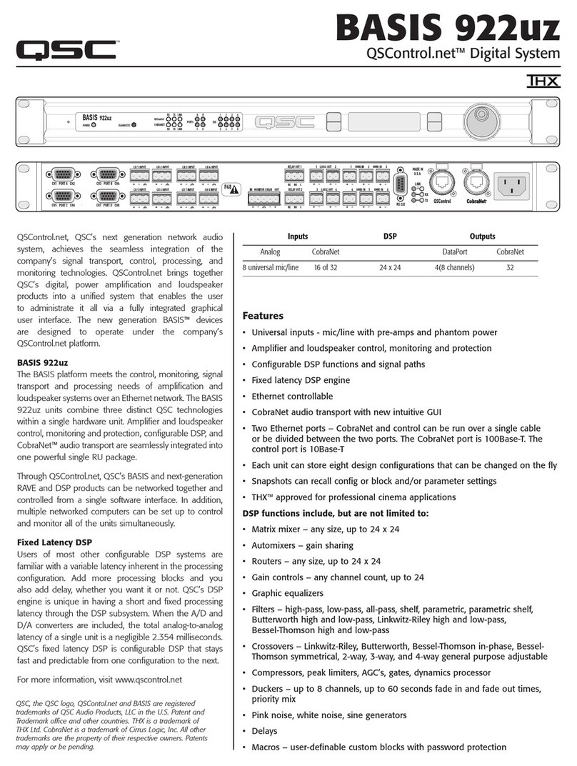
QSC
QSC BASIS 922uz Specification sheet

LY International Electronics
LY International Electronics M-9000 Series user manual
