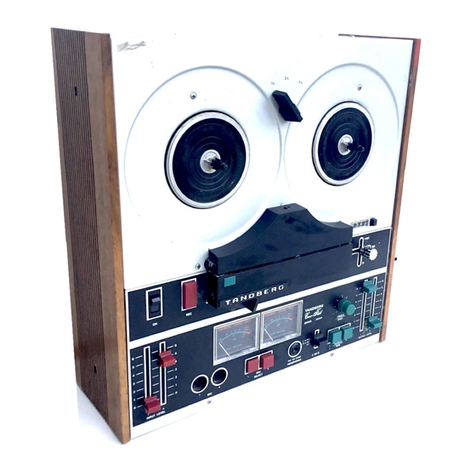
Gates CRITERION 80 User manual

r\
>
1
MONAURAL
IN
DESK
MOUNT
/
*•
P
STEREO
IN
RACK
MOUNT
CRITERION
80
i
-
r
L-
1

J
a
PRELIMINARY
INSTRUCTION
BOOK
CRITERION
80
INTRODUCTION
CRITERION
80
is
a
fully
NAB
compati le
tape
cartridge
system.
The
many
features
and
options
provide
a
model
for
every
application.
o
PROPRIETARY
NOTICE
This
document
contains
proprietary
data
of
the
Gates
Radio
Company.
'
No
disclosure
or
reproduction
of
any
part
thereof
may
e
made
without
written
permission.
888-1080-001
ii
i
I

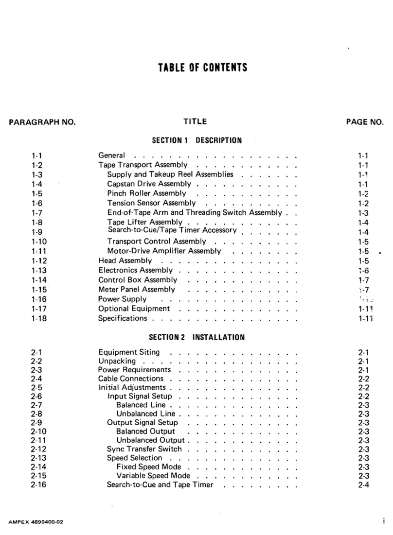
TABLE
OF
CONTENTS
i
SECTION
PAGE
INSTALLATION
1
2
OPERATION
THEORY
OF
OPERATION
3
o
4
TECHNICAL
DATA
5
MAINTENANCE
§
ADJUSTMENT
6
SCHEMATICS
7
PARTS
LIST
©
iii
1-3
1-4
2-1
2-3
Bias
Adjustment
Cue
Record
Levels
Head
Alignment
Head
Replacement
Emergency
Adjustments
Deck
Adjustments
Maintenance
Check
Lists
Play ack
Record
Amplifier
Remote
Controls
Record
Amplifier
Play ack
5-1
5-4
5-6
5-9
5-17
5-19
5-25
3-1
3-6
3-11
External
Connections
-
Record
External
Connections
-
Play ack

SECTION
1
INSTALLATION
UNPACKING
AND
INSPECTION
1.1
Remove
all
packing
material
and
carefully
lift
the
units
from
the
oxes.
Check
the
equipment
against
the
packing
slips.
Install
the
relays
according
Visually
inspect
the
to
the
enclosed
set-up
sheet.
units
for
any
apparent
damage
and
for
missing
or
Check
for
proper
operation
of
loose
components
.
the
front
panel
controls.
Any
claims
for
damage
should
e
filed
promptly
with
the
transportation
If
such
claims
are
to
e
filed,
all
agency.
packing
material
must
e
retained.
o
INSTALLATION
PROCEDURE
1.2
1.2.1
GENERAL
The
location
in
an
individual
station
will
e
determined
y
the
arrangement
of
the
main
control
The
placement
of
equipment
and
room
facilities.
wiring
should
e
planned
carefully
efore
any
Care
should
e
installation
work
is
started.
taken
to
provide
for
adequate
ventilation.
PLAYBACK,
MONOPHONIC
1.2.2
Connect
a
two-conductor
shielded
ca le
etween
the
desired
audio
console
input
terminals
and
the
600
ohm
program
output
terminals
3
and
5
of
Play ack
The
shield
of
the
ca le
should
e
connector
J2.
o
connected
to
terminal
1.
See
Figure
1.2.
1-1

PLAYBACK,
STEREOPHONIC
1.2.3
Connections
for
the
Stereo
Left
channel
are
the
same
as
for
monophonic
audio
channel.
The
Stereo
Right
channel
is
connected
to
terminals
4
and
6
with
pin
2
for
connection
to
the
shield.
Phasing
should
e
carefully
o served.
Terminals
1-3-5
are
identical
to
terminals
2-4-6
respectively.
See
Figure
1.2.
PLAYBACK-RECORD
MONOPHONIC
OR
STEREO
1.2.4
Install
tiie
Play ack-Amplifier
interconnecting
ca le
etween
connectors
J3
of
the
Play ack
and
J3
of
the
Recording
Amplifier.
Connect
the
audio
input
(monophonic
or
stereo
Left
channel)
to
terminals
3
and
5
of
JI
with
the
shield
connected
o
to
terminal
1.
For
stereophonic
installations,
connect
the
Right
channel
audio
to
terminals
4
and
6
of
JI
and
the
shield
to
terminal
2.
See
Figure
1.1.
1.2.5
REMOTE
CONTROL
CONNECTIONS
All
control
functions
of
oth
the
Play ack
and
Record
amplifier
units
may
e
remote
controlled.
See
charts
1.2
and
1.1
for
proper
connections.
Q
1-2

$3
|
o
©;
FIG.
1-1
EXTERNAL
CONNECTIONS
RECORD
AMPLIFIER
CONNECTOR
JI
FUNCTION
TERMINAL
Shield
Ground
1
Monophonic
(or
Left
stereo)
audio
input
3
5
Shield
Ground
2
Right
stereo
audio
input
(if
used)
4
6
CONNECTOR
J
3
For
Play ack
interconnecting
ca le.
CONNECTOR
J
2
1
2
Remote
Record
Set
Remote
Set
indication
3
Remote
Secondary
Tone
keying
5
8
Remote
Tertiary
(auxiliary)
Tone
keying
78
4-6-9-10
No
connection
1-3
l
-T;1
■
t
*
1
J3
©
n
©
©•
-
•••
-;?ij
.*
'//I,
>
■■

$
a
i
J3
J
1
CATES
RADIO
COMRAHY
©
0
©
©
FIG.
1-2
EXTERNAL
CONNECTIONS
PLAYBACK
CONNECTOR
JI
TERMINAL
FUNCTION
Remote
RUN
indication
1
2
Ground
1
2
Remote
Start
3
4
5
Remote
Stop
(see
Note
1)
6
7
Auxiliary
Start
(closed
momentarily
as
unit
starts)
10
11
Auxiliary
Switching
(closed
momentarily
y
Secondary
tone)
12
Auxiliary
Switching
(closed
momentarily
13
y
Tertiary
tone)
14
3
Remote
READY
indication
Remote
Tertiary
cue
indication
15
1
Remote
Secondary
cue
indication
1
9
1-4
U.S.
PATENT
NO.
3,059,063
I
S
rasa
Bra
ra
S
ra;ra
Si
era
S
rasa

CONNECTOR
J2
Shield
Ground
1
Monophonic
(or
Left
stereo)
audio
3
5
output
Shield
Ground
2
Right
stereo
audio
output
(if
used)
4
6
CONNECTOR
J3
Record-Amplifier
connecting
ca le.
These
terminals
are
strapped
together
(on
NOTE
1.
the
ack
of
the
connector)
at
the
factory.
Remove
this
strap
if
the
REMOTE
stop
facility
is
used.
1-5

SECTION
2
OPERATION
o
RECORDING
2.1
RECORDING
AMPLIFIER
CONTROL
FUNCTIONS
2.1.1
The
Recording
Amplifier
gain
control
GAIN
CONTROL:
AT-1
is
used
for
adjusting
the
recording
level
as
indicated
y
the
VU
meter
Ml.
Corresponding
AT2
and
M2
are
for
the
Right
channel
on
stereo
models.
The
Record
Set
push utton
switch
(SET)
RECORD
SET:
is
used
for
placing
the
system
in
the
recording
mode
.
The
Secondary
Cue
push utton
switch
SECONDARY
CUE:
(SEC)
is
used
for
keying
the
150
cycle
tone
o
generator.
TERTIARY
(AUXILIARY)
CUE:
The
Tertiary,
or
auxiliary,
Cue
push utton
switch
(TER)
is
used
for
keying
the
8000
cycle
tone
generator.
RECORDING
PROCEDURE
2.1.2
or
more
productions
is
as
follows:
Insert
a
ERASED
tape
cartridge
into
the
right
a)
side
of
the
cartridge
slot
in
the
Play ack
unit.
Note
that
the
STOP
indicator
is
illuminated,
indicating
the
cartridge
is
properly
placed.
)
Momentarily
press
the
RECORD
SET
switch.
The
o
2-1
switch
will
e
illuminated
y
the
internal
pilot
lamp
.
The
procedure
for
recording
one

Adjust
the
INPUT
CONTROL
so
the
program
level
c)
o
reads
0
(zero)
on
the
VU
meter
on
the
most
intense
program
peaks.
Press
the
START
switch
on
the
Play ack
unit
d)
and
start
recording
immediately.
Upon
completion
of
the
recorded
production,
e)
momentarily
press
the
STOP
switch
only
if
more
than
one
production
is
desired
on
the
same
If
only
one
production
is
to
e
used
cartridge.
on
the
cartridge,
allow
the
tape
to
continue
running
until
it
is
stopped
y
the
automatic
cue
tone
.
f)
single
tape
cartridge,
follow
the
procedure
listed
p
for
each
recording.
Upon
completion
of
the
final
recorded
production,
allow
the
tape
to
continue
running
until
it
is
stopped
s.
y
the
automatic
cue
tone.
The
1000
Hz
Primary
cue
tone
is
recorded
automatically
at
the
eginning
of
the
recording.
If
the
Tertiary
tone
is
to
e
used,
it
may
e
applied
at
any
time
during
the
recording.
If
the
Secondary
(end
of
message)
tone
is
used,
it
should
e
applied
immediately
after
the
end
of
the
program
material.
If
desired,
the
Secondary
and
Tertiary
tones
may
e
inserted
after
the
message
has
een
completely
2-2
in
Steps
c
thru
e
When
recording
more
than
one
production
on
a

This
permits
monitoring
and
accurate
recorded.
o
placement
of
the
tones.
2.2
PLAYBACK
2.2.1
CONTROL
FUNCTIONS
The
START
switch
causes
the
control
START
-
RUN
:
circuits
and
the
solenoid
to
e
energized;
and
the
tape
to
e
set
in
motion.
This
switch
is
illuminated
y
an
internal
lamp
when
the
tape
is
running
in
either
the
Play ack
or
Record
mode.
The
STOP
switch
is
used
to
manually
STOP-READY:
stop
tape
motion.
This
switch
is
illuminated
y
an
internal
lamp
when
a
cartridge
is
properly
inserted
and
the
Play ack
is
in
the
READY
mode.
o
The
ON-OFF
switch
applies
power
to
the
ON-OFF:
A
red
pilot
lamp
is
illuminated
entire
unit.
when
the
unit
is
on.
The
Program
Gain
controls
are
PROGRAM
GAIN:
and
are
used
for
mounted
on
the
main
chassis,
The
Right
adjustment
of
program
output
level.
Gain
Control
is
not
used
in
monophonic
units.
CUE
SENSITIVITY:
PLAYBACK
PROCEDURE
2.2.2
The
procedure
for
routine
on-the-air
play ack
of
program
material
is
as
follows:
2-3
The
Cue
Sensitivity
controls
are
*
mounted
on
the
respective
circuit
cards.

Insert
a
recorded
tape
cartridge
into
the
right
a)
side
of
the
cartridge
slot.
)
O serve
that
the
STOP-RLADY
switch
is
illuminated,
indicating
the
cartridge
has
een
properly
inserted,
and
that
the
unit
is
ready
for
on-the-air
play ack.
c)
Momentarily
press
the
START
switch.
Tape
motion
will
e
started
and
will
continue
until
the
automatic
cue
tone
is
picked
up
y
the
cue
head
and
the
unit
will
stop
in
the
correct
position
for
the
next
play ack.
o
o
2-4

THEORY
OF
OPERATION
SECTION
3
GENERAL
3.1
PLAYBACK
UNIT
3.1.1
The
asic
CRITERION
80
Play ack
unit
is
a
solid
state
single-tone
cue
machine
availa le
in
slide-
out
rack
panel
mounting
or
trimline
desk
console
in
either
monophonic
or
stereophonic
versions.
Second
and
third
tone
operation
is
optional.
All
versions
of
the
CRITERION
80
equipment
meet
NAB
specifications
and
offer
24
volt
DC
external
switching
for
safety
in
remote
starting
applica
tions,
and
adapta ility
to
automated
systems.
Electronics
are
of
plug-in
design;
including
relays,
circuit
cards,
front
panel
switch
o
assem lies
and
external
connections.
The
high
quality,
laminated
heads
are
uilt
with
an
all
metal
face
providing
for
long
wear
and
low
oxide
accumulation.
Improved
solenoid
action
and
shock
mounted
relays
contri ute
to
the
quiet
operation
of
the
unit,
and
the
proven
full-swing
pressure
wheel
linkage
makes
actual
studio
operation
easy
and
fool-proof.
heavy-duty
tape
transport
with
its
hysteresis
synchronous
positive
speed
direct
capstan
’
drive
3-1
o
The
heart
of
the
CRITERION
80
Play ack
unit
is
a

The
CRITERION
80
tape
transport
offers
motor
.
speed
accuracy
compara le
to
the
finest
reel-to-
reel
machines.
Sealed
precision
instrument
type
all
earings
are
used
making
transport
flutter
less
than
.25
rms
.
Plug-in
printed
circuit
oards
offer
the
finest
in
advanced
solid
state
design.
Top
quality
epoxy
glass
oard
construction
is
used
throughout
for
easy
component
access
should
maintenance
e
required
.
A
regulated
power
supply
is
used
to
power
all
circuits
assuring
correct
operating
parameters
and
relia le
operation
at
all
times.
POWER
CONTROL
BOARD:
This
card
contains
the
o
solenoid
power
supply
and
relay
as
well
shot
relay
driver
for
an
external
The
capstan
motor
may
e
connected
to
output.
run
continuously
or
to
e
switched
y
the
deck
micro
switch.
Suppressor
network
R3
and
C2
may
e
connected
across
the
deck
microswitch
or
may
e
connected
across
the
line.
Diodes
CR1
and
CR2
,
together
POWER
SUPPLY
CARD:
with
Cl,
form
the
positive
power
supply
which
is
applied
to
QI
and
Q2
in
a
compound
connected
series
Diode
CR3,
with
R1
and
C4
,
form
the
regulator.
3-2
’
’
au iliary
start
”
as
a
one-

current
limited
and
filtered
negative
supply
of
o
approximately
8
volts
used
for
reverse
ias
switching
in
the
Record
unit.
Resistors
R4
and
R5
provide
forward
ase
ias
to
QI,
which
is
regulated
at
24
volts
y
zener
diode
CR4.
Capacitor
C2
operates
as
a
pre-filter
for
QI
and
as
a
delaying
network
to
prevent
high
surge
currents
through
QI
and
Q2.
Resistor
R2
limits
the
emitter
current
of
QI
and
the
ase
drive
of
Q2
for
high
current
or
short
circuit
protection.
Fl
is
a
quick
acting
instrument
type
fuse
to
assure
protection
for
the
power
supply
in
case
of
shorts
.
At
this
point
the
voltage
is
+23
volts
and
is
further
filtered
y
R3
and
C3
to
supply
o
the
program
amplifier
cards.
Transistors
QI
and
Q2
are
PROGRAM
AMPLIFIER:
connected
as
a
oot-strap
amplifier
for
high
DC
sta ility.
C3,
R2
,
and
R9
provide
equalization,
fixed
for
low
frequencies
of
the
NAB
curve
and
adjusta le
at
high
frequencies
to
compensate
for
head
losses
and
allow
the
choice
of
operating
curves
to
match
3-3/4,
7-1/2,
or
15
IPS
require-
R1
and
R4
provide
local
AC
feed ack
for
ments
.
these
stages
to
increase
AC
sta ility.
control
as
an
input
load.
R14
and
R12
provide
3-3
Q3
is
a
medium
impedance
amplifier
matching
the
gain

feed ack
for
AC
sta ility.
Q4
is
a
Class
A
o
impedance
matching
output
amplifier
working
into
line
transformer
Tl.
switch
to
allow
operation
from
the
+23
volts
The
LDR
provides
a
slight
delay
in
the
supply.
output
of
the
program
amplifier
to
suppress
start
up
noises.
1
kllZ
PRIMARY
CUE:
QI
and
Q2
comprise
a
road and
amplifier
to
provide
high
input
impedance
and
high
current
gain
suita le
for
driving
all
the cue
sensors,
which
are
compounded
AC
feed
ack
for
Q2
is
provided
y
R5.
Signal
is
coupled
to
the
cue
gain
control
R7
,
where
cue
sensitivity
for
the
1
kHz
sensor
is
set.
C7
allows
low
fre
quency
degeneration
for
Q3,
C8
provides
high
frequency
limiting
action.
Q4
is
a
similarly
tuned
stage;
the
result
is
a
passive
two-stage
amplifier
at
1
kHz,
with
roll-off
on
either
side
at
approximately
12
dB
per
octave.
Q5
and
Q6
signal
rectifier
and
DC
amplifier,
Q6
is
Q9
is
a
relay
driver
and
is
o
ridging
network.
normally
in
saturation
through
ias
resistors
R21
When
a
cue
signal
and
R29
to
the
positive
supply.
3-4
)
o
R19
is
a
voltage
dropping
resistor
for
the
lamp
element
of
the
LDR
audio
operate
as
a
with
C13
providing
a
delaying
action.
connected
to
the
ase
of
Q9
through
a
resistance
as
a
load.

is
detected,
Q6
will
remove
the
drive
from
Q9
and
o
cause
relay
KI
to
drop
out;
provided
that
Q7
is
not
conducting.
The
time
delay/protect
circuit
receives
run
voltage
from
relay
KI
through
R33.
C14
charges
through
R32
to
the
avalanche
voltage
Q10
conducts,
providing
a
of
uni-junction
Q10.
gate
signal
for
Qll;
which
fires,
latches,
and
drops
its
anode
voltage
across
R33
nearly
to
zero.
During
this
timing
interval
Q8
is
ON
holding
Q7
ON,
which
holds
Q9
ON.
In
this
way
Q9
can
not
e
turned
OFF
y
a
cue
signal
until
after
the
time
delay
cycle.
A
positive
input
to
the
ase
of
Q8,
through
R26
from
the
150
Hz
sensor
card,
provides
safety
muting
during
o
reception
of
150
Hz
tones.
R26
may
e
removed
if
this
feature
is
not
desired.
150
HZ
SECONDARY
CUE:
The
amplified
cue
signal
is
received
from
the
1
kHz
card.
Rl,
Cl
and
sensi
tivity
control
R2
form
a
low-pass
network
into
the
C14
provides
low
frequency
degeneration
ase
of
QI.
and
C3
provides
high
frequency
attenuation
for
QI.
Q2
is
in
a
similar
circuit,
resulting
in
a
passive
amplifier
with
slopes
either
side
of
center
fre
quency
of
approximately
12
dB
per
octave.
Q3
and
Q4
operate
as
a
signal
rectifier
and
DC
amplifier
for
the
relay,
with
C9
providing
a
delaying
action.
3-5
o

An
output
is
taken
from
the
collector
of
Q4
ack
the
1
kHz
card
for
safety
muting
during
o
The
relay
is
normally
the
150
Hz
operation.
returned
to
the
anode
of
Qll
on
the
1
kHz
card
to
allow
150
cycle
sensor
operation
only
after
the
protect
timer
interval
has
passed.
8
kHZ
TERTIARY
CUE:
The
amplified
cue
signal
is
received
from
the
1
kHz
cue
card.
Cl,
CIO
and
sensitivity
control
R2
form
a
high
pass
network
feeding
QI
in
this
circuit.
The
safety
and
inhi it
functions
utilized
in
the
150
Hz
card
are
not
utilized
in
this
circuit,
which
otherwise
functions
the
same
as
the
150
Hz
cue
circuit.
o
3.1.2
RECORD
AMPLIFIER
solid
state,
single-tone
cue
device
for
use
in
association
with
any
monophonic
model
CRITERION
80
Play ack.
The
Recording
Amplifier
is
also
availa le
in
slide-out
rack
panel
mounting
or
trim
line
desk
console
in
either
monophonic
or
stereo-
Second
and
third
tone
operation
phonic
versions.
Operation
on
regulated
DC
power
from
is
optional.
the
associated
Play ack
unit
assures
correct
The
printed
operating
parameters
at
all
times.
circuit
oard
mounting
of
all
components
in
the
o
CRITERION
80
Recording
Amplifier
provides
for
easy
.
3-6
to
Q8
on
The
asic
CRITERION
80
Recording
Amplifier
is
a

and
efficient
maintenance.
Pre-wired
PC
plugs
o
permit
easy
field
modification
of
any
single
tone
amplifier
to
three-tone
operation.
RECORD
AMP/METER
AMP:
Transistor
QI
is
a
common
emitter
amplifier
with
R2
providing
local
AC
C2
slightly
oosts
high
frequency
gain
feed ack.
to
compensate
for
reactive
losses
in
the
input
The
output
of
QI
feeds
oth
the
meter
network.
gain
control
(R13)
and
the
pre-emphasis
network
The
input
to
consisting
of
C5,
R6
,
C6
and
R9.
the
ase
of
Q2
is
fed
from
this
network,
and
additionally
shaped
y
C8,
C9
and
LI
to
drive
the
recording
head.
L2
and
CIO
form
a
ias
trap
to
limit
ias
on
the
collector
of
Q2.
Transistors
o
Q3
and
Q4
make
up
high
input
and
low
output
impedance
to
drive
the
meter
and
its
ridge
rectifier.
BIAS
OSCILLATOR:
Transistors
QI
and
Q2
operate
as
a
Class
AB
push-pull
oscillator,
with
transformer
T1
and
C4
as
a
tuned
load.
AC
positive
feed ack
is
provided
through
C2
and
C3.
Negative
feed ack,
for
sta ility,
is
developed
across
R2
and
RS.
Output
is
taken
from
three
taps
on
the
transformer
through
resistors
R8
,
R9
and
RIO,
which
provide
resistive
loads
and
current
limiting
while
the
switching
transistors
are
AC
grounded.
o
J
Q3,
Q4
and
Q5
are
saturated
gates
to
allow
selective
3-7
a
oot-strap
amplifier,
providing

application
of
ias
to
any
of
the
three
outputs.
o
Trimmer
C5,
C6
and
C7
provide
independent
ias
adjustments
for
each
head
section.
Diodes
CR1
and
CR2
turn
on
the
ias
oscillator
y
voltage
from
the
SET
utton
or
the
two-tone
oscillator
DC
reverse
drive,
to
open
the
card,
when
keyed.
clamping
gates,
is
derived
from
these
same
Resistor
R1
and
capacitor
Cl
voltage
sources.
filter
the
DC
power
applied
to
the
oscillator
circuit,
to
prevent
false
triggering.
This
card
includes
1
kllZ
PRIMARY
CUE
OSCILLATOR:
the
1
kHz
oscillator
and
a
timer
circuit,
which
automatically
applies
a
1
kHz
signal
at
the
start
o
of
each
recording
operation.
Transistor
QI
and
associated
components
form
a
tuna le
shunt-fed
Hartley
oscillator.
Potentiometer
R5
is
the
primary
cue
level
control,
and
serves
as
the
oscillator
load.
The
1
kHz
tone
is
coupled
into
amplifier
Q2;
the
150
Hz
tone
and
the
8
kHz
tone
are
also
fed
into
the
card
through
terminal
2
Thus,
Q2
acts
as
a
common
amplifier
into
Q2.
The
timer
section
of
the
card
gets
its
power
through
terminal
12,
which
starts
charging
CIO
o
3-8
for
all
three
tones,
which
are
then
coupled
through
the
ias
trap
to
the
cue
record
head.
Table of contents
