Gator TRADE Series User manual

7” Quad display AHD Monitor
with Heavy Duty AHD Camera
GT704HD
If you need assistance setting up or using your Gator product now or in the future, call Gator
Support.
Australia
TEL: 03 – 8587 8898
FAX: 03 – 8587 8866
Mon-Fri 9am – 5pm AEST
Please retain this user guide for future reference.
If you would like to download a digital copy of this manual, or other Gator manuals/software,
please visit the http://gatordriverassist.com website and click on ‘Firmware & Manuals” for
information on where to find the manuals/software.
This manual is considered correct at time of printing but is subject to change. For latest manuals
and updates refer to the website.
Copyright © 2017 by TDJ Australia
All rights reserved. No part of this publication may be reproduced, distributed, or transmitted in
any form or by any means, including photocopying, recording, copying or other electronic or
mechanical methods, without the prior written permission of the author.
Technical assistance
www.gatordriverassist.com
Remote control functionality
1. Power ON/Off
2. Up
3. Left
4. Down
5. Right
6. Menu
7. Mode select
8. Direct Channel select

1. Power ON/Off
2. Camera input viewing modes.
3. Ch1 view (Menu-navigate)
4. Ch2 view (Menu-navigate)
5. Menu
6. Ch3 view (Menu-navigate)
7. Ch4 view (Menu-navigate)
8. Remote sensor
P1 P2
1 x Hi-Resolution Monitor
1 x CMOS camera
1 x Wire harness
1 x Sun shade
1 x U-bracket
4 x U-bracket screws
1 x Remote controller
Product structure
Inclusions Monitor functionality & settings
NOTE: AHD monitors require AHD cameras
(Compatible cameras)
GT13AHD GT18AHD
Monitor Features
•
•
•
•
•
•
•
•
•
•
•
•
•
7” High Resolution Monitor (AHD)
Resolution 1024x600 RGB
Bright 450CD Display
Aspect Ratio: 16:9
4X AHD Video Inputs
Video input format 720P,960P & 1080P HD
25/30 FPS PAL/NTSC
PAL/NTSC Auto Switching
10 Metre Main harness Prolink II
Rear View Delay (0~15S selection)
High/Low Voltage & Short Circuit Protection
12/24 Input Voltage
Detachable Sunshade
Supplies 12V Power to Cameras
•
•
•
•
•
•
•
Camera Features
960P @ 30 FPS High Resolution (AHD)
120 Degree Wide Angle Lens
Rated IP68 Waterproof
NTSC
Minimum Illumination: 0 Lux
10 IR LED’s
1/3” Image Sensor
CH1/ CH2/ CH3/ CH4/

7 Pin Plug
Extra for Flat 12 Pin Plug
Pin
1
2
3
4
5
6
7
Pin
8
9
10
11
12
Connection
Left Indicator
Auxiliary or Reverse Light
Earth
Right Indicator
Electric Brakes
Stop Light
Tail Lights
Connection
Left Indicator
Auxiliary or Reverse Light
Earth
Right Indicator
Electric Brakes
Colour
Yellow
Black
White
Green
Blue
Red
Brown
Colour
Orange
Pink
White
Grey
Violet
Common Trailer pin configurations (Always check your individual trailers wiring in case its not standard)
1
6
5
3
2
7
44
72
3
5
61
1 1
2
3
2
3
7 7
4
5
6 6
5
4
1
6
5
3
10
11
7
4 2
12 96
1 6
5
69
3
10
2
11
7
12
4
7 Pin Flat
7 Pin Round
12 Pin Flat
Socket View Plug View
Socket View Plug View
Socket View Plug View
P3 P4
Menu structure
Press the (Menu) Button once to enter the menu system. Use the Ch3 and Ch4 to
navigate up or down the menu. Use the Ch3 and Ch4 buttons to navigate within the
sub menu then press the Mode button to change to the highlighted setting.
Press the menu button to exit a Menu or a Sub Menu.
Note: the menu only displays 4 features at a time scroll down past the last menu item to
reveal the next feature.
The menu structure is in the following sequence.
Language
Reversing Delay (can also be used for blind spot cameras),
Power Off Screen
TV Mode
Turnover
System Recovery
Firmware Version
Back light adjustment.
To finish you must exit the menu system by pressing the Menu button.
Menu item descriptions.
1. Language:
Selects between English and Chinese
2. Reversing delay (this is a global setting that works on all channels/cameras:
A delay off can be set for all cameras channels of up to 10 seconds. This sets the Switch
off time after the Trigger is removed. This function only operates when a camera is
Triggered. For example the vehicle is in reverse and so the back up light wire of the car
triggers the back camera to turn on automatically or switch from another channel across
to the backup camera. When the trigger is lost ( the vehicle is taken out of reverse) the
Image is normally switched off or the monitor returned to its previous state. A delay time
allows the camera to stay on for a prescribed amount of seconds after the trigger is lost.
Using delay for blind spot priority when changing lanes. The off delay can be used to
keep a camera on when a trigger is intermittent like in the case of using the indicator bulb
positive as a trigger to turn on a camera that views the blind spot on that side of the
vehicle. When set to as little as 3 seconds the camera will stay on when changing lanes
with the indicator on even though the trigger is not constant (on/off, on,off etc etc).
3. Power Off Screen
This sets the time between 1,3 and 5 min till the monitor switches off when there is no
signal.
4. TV mode: NTSC or PAL selectable
5. Turnover: Ch1/ Ch2/ Ch3/ Ch4. Use the Ch3 and Ch4 to select Channel. Ch2
button to turn on or off. Press Mode button to exit. Use Use the Ch3 and Ch4 to select
original image preview or left and right turnover. This will mirror the input image left or
right.
6. System recovery: Resets back to factory settings
7. Firmware version: Operating software version
8. Back light adjustment : Use the Ch3 and Ch4 to increase or decrease the back
lighting.

Note: When connecting the main harness
to the monitor, firmly press together to
ensure plug is fully recessed.
P5 P6
Quad wiring diagram
* Trailer Kit Model
GTTKIT
**Extension Model
PLC5
PLC10
PLC15
PLC20
*** Add on Camera Models
GT13AHD
GT18AHD
GND
+12V acc
AV2
Monitor
AV2
Trigger
AV2 Trigger connect to
reverse bulb. Refer diagram
for nding polarity. (Fig1)
10 metre extension included
AV 3 trigger
connect to left
signal bulb
AV3
AV4
Trigger
AV1
Trigger
AV1
AV4
Rear camera
included
AV 4 trigger
connect to right
signal bulb
Camera and Extension
Sold Separately *
Camera and Extension
Sold Separately *
Camera and Extension
Sold Separately *
AV3 Trigger
Note: When side cameras are used for blind spot view
connect the trigger wire for the left camera to the left
signal bulb positive and do the same for the right
camera. Add a delay time of around 5 seconds to left
and right cameras to compensate for the intermittent
triggering from the turn signal bulb.
12.8V
RED BLK
DC V
Positive when
vehicle
is in reverse
Multimeter shows a
negative voltage
12.8V
REDBLK
DC V
Positive when
vehicle
is in reverse
Multimeter shows a
Positive voltage
Bulb Bulb
Fig1

How to find reversing wires to trigger or power backup camera systems.
We recommend that you wire up the triggers as the last part of your installation (after the
systems monitor has been wired) this is so that you can use the system as a safe way to test
for a reversing wire.
Back up camera systems (reversing camera systems) require a signal to “Trigger” the system
into action so that it automatically operates when the vehicle is in reverse.
Whilst some systems are designed to allow cameras to operate even when the vehicle is not
in reverse it is still necessary to wire a trigger system in so that the Camera that is facing
backward automatically turns and or takes over as priority when in the vehicle is in reverse.
When wired in correctly using the right trigger priority, the system can also automatically turn
on the rear camera of an attached trailer taking priority over the vehicles back up camera
when the trailer is connected.
The most common way to trigger the rear facing camera is to use the + wire that powers one
of the vehicles reversing globes at the back of the vehicle.
NOTE: Some vehicles that Use CAN bus to operate rear lighting systems may require
additional parts to trigger the system.
Caution: Never test for reversing wires standing at the back of the vehicle, with the engine
running and the gearbox in reverse gear. If the car/truck can not be placed in reverse without
the engine running, Special procedures should be employed. In this case we highly
recommend you seek a professional installer to do this type of work. Failure to follow proper
procedure could cause serious injury or death. (The vehicle could back over you)
Step 1.
Place the car in reverse, with ignition on but the car not running (do not leave the cars ignition
on for long periods of time without starting it) observe or have an observer notice which light
turns on and its location in the lens. Turn the ignition off. Then, locate the globe socket that
holds the reversing globe into the lens. In some cases the Lens has to be removed from the
car to expose the socket. In most cases however, you can gain access from the inside of the
car behind a removable interior wall/panel.
Step 2.
Identify which wire is the globes ground and which is positive (see Fig 1 diagram). Light globes
have very low resistance so if a globe is in place, both wires will show up as a ground. Even if
you remove the globe the second globe on the other side of the vehicle will still give the
positive side a short path to ground and may still be indistinguishable from the globes earth.
For this reason it is necessary to energize the globe to find out which side is positive and
which side is negative.
Using a multimeter set to DC volts (make sure that it is on the correct scale) attach the
negative probe to one of the globes wires and the positive probe to the other (in most cases
you can push the probe ends into the back of the globe socket) if not, you may have to
carefully strip both wires sheaths back to expose the wires core making sure you keep
them separate and away from the cars chassis to avoid any shorts). You should also
make sure the globe it self is not resting on something that could be harmed by extreme
heat as the globe when on can get very hot). Turn the ignition back on again with the cars
gear set to reverse (without the engine running). The globe should illuminate and the
multimeter will show a positive voltage or a negative voltage across the globe. By noting
whether the voltage is positive or negative you can define which wire is positive or
negative. If the reading is positive then the probes positive is connected to the positive
wire. If it’s a negative reading then the multimeter's negative probe is connected to the
positive wire of the globe as a final check, take the vehicle out of reverse with the ignition
still on and check that the voltage is now zero.
If the vehicle can not be placed in reverse without the engine running the following
procedure should be used. With the car off, remove the globe. Set your multimeter to
resistance on the lowest setting. Place one probe on a part of the chassis that is ground
(most rear tail light assemblies have a small grounding screw close by). If you can not find
one look for some exposed chassis (like a tailgate hinge etc). Measure the resistance to
ground of both wires in the back of the globe socket (with the globe out) whist the
resistance will be very similar (because of the other globe still in the circuit) one wire will
have a slightly higher resistance. The one with the highest resistance should be the
positive wire.
Connect the system to this wire and then use the reversing system to test if it is triggering.
With no one at the rear of the vehicle. Start the car. Make sure the reversing systems
monitor is in the off state and then place the vehicle in reverse. If you have found the
correct wire the system will automatically turn on from its off state. If you have connected
the trigger to the globes earth no harm is caused but the system will not trigger. In that
case simply connect it to the alternate wire and repeat.
CAN BUS
In the event that the cars reversing lights are driven by CAN BUS the above wiring system
may not trigger the system correctly. It may even create a globe fault warning. In this case
a CAN BUS module (sold separately) may need to be installed. However, just because the
vehicle has a CAN BUS system does not necessarily mean that it will require such a
module to work. In fact the opposite is true. Most vehicles do not require an additional
module. If a CAN BUS module is required we recommend seeking advice from a
professional installer.
Multi trigger systems. Please refer to the diagram provided with trailer trigger systems.
Pay special attention to the AV camera numbers and trigger numbers. It is important that
the AV camera numbers match the diagrams placement in order to provide the correct
priorities so that when a trailer is connected it takes rear view priority over the vehicles
rear view camera and so that when no trailer is connected the vehicles rear camera
operates automatically.
P7 P8

P9 P10
GT704HD configurations
Scan the QR code to go to our website. Click on the icon for a full schematic wiring
diagram to suit your installation.
Note: Additional cameras and wiring may be required depending on your
application, compatible products are available on our website.
This system comes with one camera as illustrated above, however it is capable of
running up to 4 cameras and can cover a very large array of vehicle requirements.
The following diagrams show some additional (but not all), configurations that the
system is capable of handling with the addition of some extra cameras and associated
accessories. Please refer to our web site for detailed schematics of these installations.
This camera can be used for reversing or as a rear-view mirror substitute
Turn signal activated used as blind spot detection.
Having two cameras at the back, one camera can be optimised for parking (top down view)
whilst the other can look backwards and be used as a rear-view mirror substitute.
x2
x2
x2
Turn signal activated used
as blind spot detection
Turn signal activated used as blind spot detection
Turn signal activated used as blind spot detection
Turn signal activated used as blind spot detection
This manual suits for next models
1
Other Gator Monitor manuals
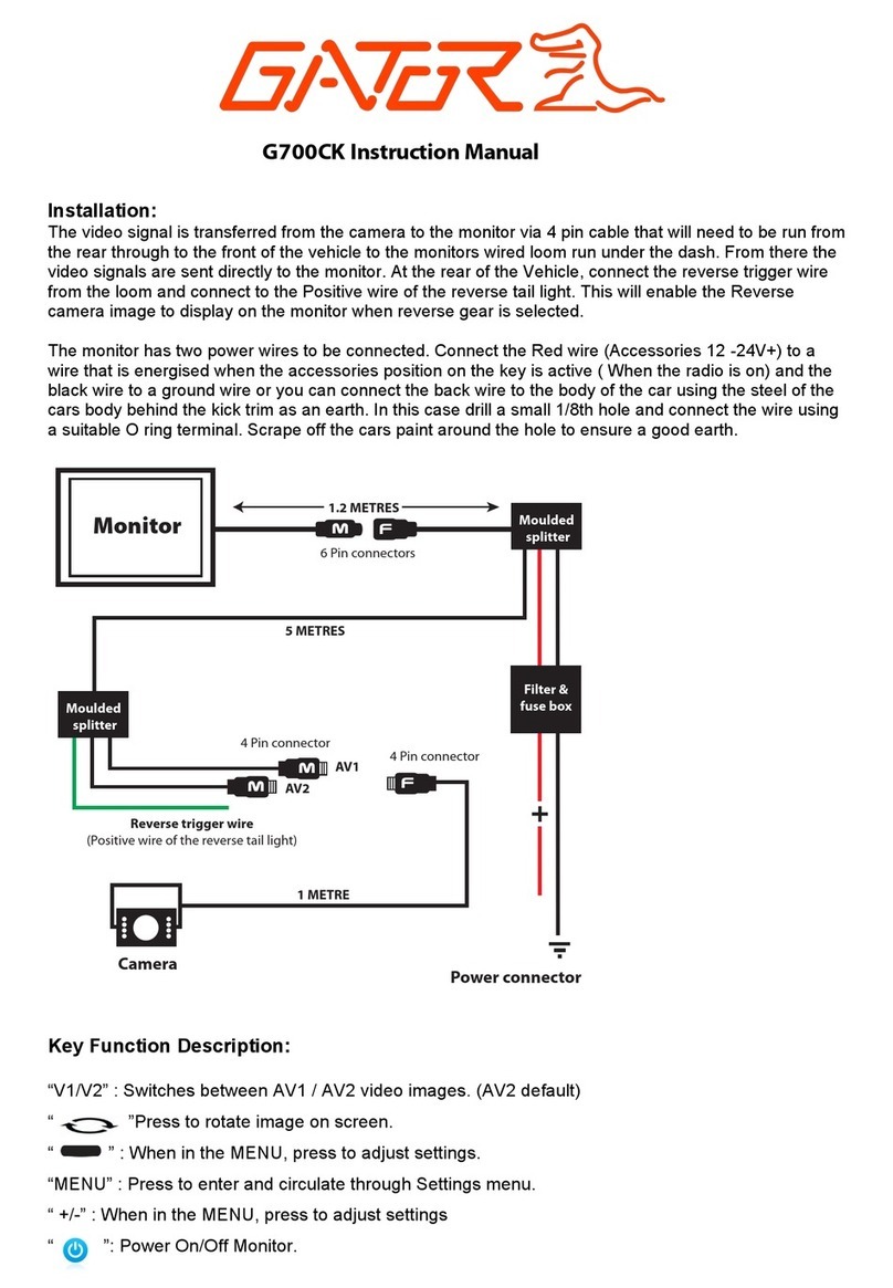
Gator
Gator G700CK User manual

Gator
Gator GT704DVR User manual

Gator
Gator GALT01 User manual

Gator
Gator GT700WP User manual
Gator
Gator GT700W2 User manual
Gator
Gator GRV127KT User manual
Gator
Gator GT70SDTK User manual
Gator
Gator GT904SD User manual

Gator
Gator GT7045D TRADE Series User manual
Gator
Gator G390 User manual

