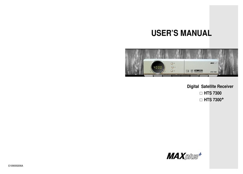
GbSat Desire User manual

The 2C1 20 GbSat for the
reception of PayTV and FTA
channels turned out to be every
bit as good as advertised.
TELESATELLITEINTERNATIONAL02-03-2002
Audio fans will really enjoy the
digital audio output and the
ability to transfer MP3 digital
audio to a PC hard drive.
TELESATELLITEINTERNATIONAL02-03-2002
It deserves high praise for its
SatcoDX compatibility and for
its USALS protocol integration.
TELESATELLITEINTERNATIONAL02-03-2002


Contents
Safety Information II
1. Before You Begin BYB.1
1.1 Features BYB.1
1.2 Accessories BYB.2
2. Controls and Functions CAF.1
2.1 Front Panel CAF.1
2.2 Rear Panel CAF.2
2.3 Remote Control Unit CAF.3
3. Connections CON.1
3.1 Connecting to TV & VCR CON.1
3.2 Connecting to Dish CON.4
4. Installation and Operation IAO.1
4.1 Menu Information IAO.1
4.2 Common Interface (except FTA) IAO.14
4.3 CAS Embedded (CAS only) IAO.14
4.4 Viewing General Information IAO.15
4.5 Personal Video Recorder (PVR only) IAO.16
5. Additional Information AI.1
5.1 Trouble Shooting AI.1
5.2 Technical Specifications AI.3
5.3 Glossary of Terms AI.7
5.4 Menu Structure AI.9
5.5 MP3 Juke Box AI.10
5.6 Internal positioner Setup AI.11
Contents I

Safety Information
•Be sure to read this User's Manual before starting the operation
of the receiver.
•DO NOT OPEN THE COVER. It is dangerous to touch the inside
of the receiver due to possible electric shock. Removing the
cover will also invalidate your three year warranty.
•Use a soft cloth and a mild solution of washing-up liquid to clean
the case.
•If the receiver is unused for a long time, unplug the power cord
from the wall outlet.
•Do not connect or modify cables when the receiver is plugged in.
•Do not use a damaged power cord that may cause a fire or an
electric shock.
•Do not touch a power cord with wet hands. It may cause an
electric shock.
•Place the receiver in a well-ventilated and cool environment.
•When connecting cables, the receiver must have been powered
off.
General Information
This manual provides complete instructions for installing and using
the receiver. All functions of the receiver can be carried out using
the buttons on the remote controller and many of the functions can
also be carried out using the buttons on the front panel.
If you have any problems with the operation of your receiver, please
refer to the relevant section of this manual or call your dealer.
Contents II

1. Before You Begin
1.1 Features
•MPEG-2 & Fully DVB compliant
•MPEG-2 Video (MP@ML), MPEG-1 Audio Layer1, Layer2
•PLL RF-Modulator UHF 21-69 with PAL I / G/B / D/K
•LNB Controlling Logic (0/22KHz Tone, 13/18V 14/19V)
•SCPS/MCPC Receivable from C /Ku-Band Satellites
•Digital Tuner with Loop-through
•Wide Symbol Rate 1-45Mbps & Frequency Input 950-2150MHz
•DiSEqC 1.2 with USALS
•2 SCART for TV, VCR + phono Audio Video
•User-friendly, Full Function OSD Menu
•256 Colours Graphic User Interface
•Multi-language Menus (English, French, German, Spanish,
Italian and Russian)
•4-digit 7-segment LED Display
•Variable Aspect Ratio (4:3,16:9) with Pan Vector or Letter Box
•EPG (Electronic Program Guide) for Channel Information
•Small Screen Picture on EPG Channel Edit modes
•Teletext and Subtitle Supported (VBI & OSD)
•Easy Setup & Installation
•Capacity for Storing Multiple Channels
(FTA. 2000 Channels, 500 Transponders)
(CI. 4000 Channels, 1000 Transponders)
•3 Favourite Channel lists
•Parental Lock –Password protected
•RS232C Port for Additional InformationService and Upgrading
System Software
•2 Slot Common Interface slots (except FTA) for ViAccess,Conax,
Crypto Works(TM), Nagravision,Irdeto and MEDIAGUARD
Before You Begin BYB.1

1.2 Accessories
•User’s Manual
•Remote Control Unit
•Batteries
Figure 1. Accessories
BYB.2 Before You Begin

2. Controls and Functions
2.1 Front Panel
A. Power Button
Turns the receiver On/Standby.
B. Up/Down Button (/)
Changes channels in viewing mode and moves the cursor up / down
in menu mode.
C. Left/Right Button (/)
Increases / decreases the volume levels in viewing mode and
changes settings in menu mode.
D. Display (4-digit 7-segment)
The 4-digit displays channel information. In Standby mode, the
7-segment displays local time. In Standby mode, a red LED
indicator is illuminated.
E. Menu/OK Button
Displays the Main menu in viewing mode. Activates the highlighted
menu item in menu mode.
F. Exit Button
Exit from the current menu or cancels the current operation.
Controls & Functions CAF.1

2.2 Rear Panel
A. DISH IN 13/18V 500mA Max
Connect the LNB cable from the satellite dish.
B. LOOP OUT
Loop Out is an output port of the DISH IN signal.
C. AERIAL IN
Connect the terrestrial TV antenna to Aerial IN.
D. RF OUT
Connect a conventional UHF TV.
E. RS-232C
Connect a Set-top box or a serial port of PC.
F. AUDIO, VIDEO
AUDIO/VIDEO output. Connect Red and White connector to
Audio R and Audio L, and Yellow into Video port respectively.
G. SCART for TV, VCR
Connect the TV/VCR together with SCART cables.
H. Electric Inlet Lead
Connect AC (Auto-selectable), 50-60Hz. Make sure to check
the power specification.
I. On/Off switch
J. 6P Push Terminal for Postioner
Connect the Positioner.
K. S/PDIF (Fiber-Optic Connector)
Audio output for connection to a digital amplifier.
Optional
CAF.2 Controls & Functions

2.3 Remote Control Unit
All features of the receiver can be controlled using the remote
control.
A. Power
Turns the receiver
On/Standby.
B. MUTE
Turns the sound On/Off.
C. NUMERIC KEY
Controls the numerical
operation. Key in direct
access to any channel.
D. TV/Radio
Switches between TV and
Radio.
E. OK
Confirms the choices and
selection with the
highlighted menu item.
Press the OK button to
display the channel list.
F. UP/DOWN
Changes channels in
viewing mode and moves
up/down in menu mode.
G. LEFT/RIGHT
Changes the volume level in viewing mode and settings in menu
mode.
H. MENU
Displays the Main menu in viewing mode and the TV/Radio
program screen in menu mode.
Controls & Functions CAF.3

Double arrow UP/DOWN
Move to the next or previous list / text page if more than one page is
available.
I. EXIT
Exit from the present menu and moves to the previous menu.
J. EPG
Displays the TV/Radio program guide.
K. Information
Displays any information transmitted by the program provider
about the current program. Press the button on the
information mode to display the detail EPG box. Press theExit
button to remove the box. Press the button again if the EPG
information is more than one page.
L. TEXT
Displays the Teletext contents ifTeletext is transmitted.
M. Favourite -Red
Displays the current favourite channel list. Refer to 4.3 Viewing
General Information-Favourite Channel List for more details.
N. Sleep
Sets the time for turning the receiver off (10 –120 mins).
O. Recall -Blue
Moves to the previous channel.
P. Audio -Green
Audio control toggles through several modes:
Q. Language -Yellow
Displays the available multi-language Audio tracks.
R. Function
Normally used to sort channels alphabetically or numerically.
CAF.4 Controls & Functions

3. Connections
•Install the receiver in an horizontal position.
•Do not put any heavy equipment such as a TV on the receiver.
•Ensure the receiver is installed in an area away from vibration,
direct sunlight, high humidity and extremes of temperature, but is
well ventilated.
3.1 Connecting to TV & VCR
UHF and Line Out
1. Connect the TV antenna to AERIAL IN.
2. Connect the RF-OUT to RF-lN of TV.
3. Connect the Video and Audio to the TV Video and Audio.
Connect Red and White connector to Audio R and Audio L and
Yellow into Video port respectively.
4. Go to section 3.2 Connecting to Dish, then connect your dish.
Connections CON.1

UHF and Line Out with Video
1. Connect the TV antenna to AERIAL IN.
2. Connect the RF-IN of VCR to RF-OUT with RF cable.
3. Connect the RF-OUT of VCR to the RF-IN of TV
4. Connect the Video and Audio to the TV Video and Audio.
Connect Red and White connector to Audio R and Audio L, and
Yellow into Video port respectively.
5. Go to section 3.2 Connecting to Dish, then connect your dish
CON.2 Connections

Receiver to TV and VCR with SCART Cables
1. Connect the TV antenna to AERIAL IN.
2. Connect the RF-IN of VCR to RF-OUT with the RF cable.
3. Connect the RF-OUT of VCR to the RF-IN of TV.
4 Connect the Video and Audio of TV to the Video and Audio.
Connect Red and White connector to Audio R and Audio L, and
Yellow into Video port respectively.
5. Connect the TV SCART to TV with fully wired SCART cable.
6. Connect the VCR SCART to VCR with fully wired SCART cable.
7. Go to section 3.2 Connecting to DISH, then connect your dish.
Connections CON.3

3.2 Connecting to Dish
Dish
Connect the satellite antenna cable to DISH IN.
2. Fixed Dishes Using DISEQC
Connect the output ofDiSEqC 1.0 switch to DISH IN of the receiver.
CON.4 Connections

Motorised Dish Using DiSEqC 1.2 & USALS
Connect a USALS motor to DISH IN of the receiver.
Motorised Dish Using Positioner
Connect the output ofPositioner to DISH IN of the receiver.
Connections CON.5

4. Installation and Operation
4.1 Menu Information
Installation
During the installation, a short piece of information is displayed at
the bottom of the menu screen. After you finish the setup procedure,
you can start watching TV or listening to Radio.
1. Turn on your TV and receiver.
2. The pop-up menu for
language selection will appear.
Select one language and press
the OK button to proceed.
Press the MENU button to
display the main menu.
3. A menu will now appear on
the TV screen. Selectable lines are
generally highlighted. To select a
menu item, press the OK key. Most
of the menus display extra
information at the bottom of the
screen.
IA0.1 Installation & Operation

Using the Up/Down (/)button, you can move upwards
and downwards in the menu.
•Once selected, press theOK button to confirm your selection.
•When you want to return to the previous menu or mode, press
the OK button.
4. Press the OK button on the
Installation option. The Password
window will appear. Enter the default
password "0000" with the numeric
keypad.
5. Dish Setup
Press the OK button on the Dish
Setup option. The following window
will appear.
A. Internal Positioner.
The right screen displays a list of 32 pre-programmed satellites. If
you want to change a satellite, select it on the right screen. Press
the OK button on the required satellite in the right screen. The dish
number will change to the selected satellite.
Installation & Operation IA0.2

B. USALS Positioner.The right
screen displays a list of 32
pre-programmed satellites. If you want
to change the satellite, select the
satellite on the right screen. Press the
OK button in the right screen. The dish
number will change to the selected
satellite.
C. Transponder. The column on the
right will display the transponder list for
the selected satellite. If you select one
of the alternative satellite names, then
the transponder list will be changed
accordingly.
D. LNB Power. The column on the right will display the LNB Power.
Normally, you should select the 13v/18v LNB Power and
9,750/10,600 LNB Local frequency for your universal LNB. You may
select the 14v/19v setting if you are operating a longer LNB cable.
E. If you are using aDiSEqC 1.0
switch for up to 4LNB’s, then select
the correct switch type, i.e. DiSEqC
and then select the correct port (A,B,C
or D) for your satellite. Refer to the
switch manufacturers, instructions.
IA0.3 Installation & Operation

F. If you connect aDiSEqC 1.2
motor without USALS to the
receiver, select the switch type to
Motor. Change the position of your
Motor using the Option parameter.
•Done: Press OK button on the
right screen, position of cursor will be changed to the left screen.
•Move West-East: Press the (/) button, the motor position
will be changed to West / East.
•Store Position: Press the OK button to save the current
position.
•Go to Position: Press the OK button to move the motor to a
stored satellite position.
•Go to Reference: Press the OK button to move the motor to the
0 position.
•Set West Limit: Press theOK button to fix West limit.
•Set East Limit: Press theOK button to fix East limit.
•Enable Limit / Disable Limit: Press the OK button to change.
(To enable Limits, go to the last parameter in Option and toggle
Disable/Enable using the (/) button.)
G. When your receiver is connected to a traditionalpositioner,
select "Initialize Dish" first, then set the east and west limit of the
positioner, which will be stored automatically.
WARNING: Please check the positioner wire connections on the
rear of the receiver before activating the positioner using the menu.
Select the "Move West-East" menu, press (/) button to seek
the satellite position. To save the selected satellite position, move to
"Store Position" and press OK button.
•During the seeking process, if you go past a signal coming from
a satellite, adjust the dish position by pressing the (/) button
until you peak the signal Quality Bar.
Installation & Operation IA0.4

5.1 USALS (UNIVERSAL SATELLITE AUTOMATIC LOCATION
SYSTEM)
First get your Longitude and Latitude for your dish location. Then,
select USALS on the Switch type of Dish Setup menu. After the
Longitude and Latitude have been entered, the calculated USALS
values will be displayed.
Execute "Go to Position” of the "Option" menu to move the dish to
satellite position. Other functions are the same as DiSEqC 1.2.
•Done: Press OK button on the right screen, position of cursor
will be changed to the left screen.
•Move West-East: Press the (/) button, the motor position
will be changed to West / East.
•Store Position: Press the OK button to save the current
position.
•Go to Position: Press the OK button to move the motor to the
stored satellite position.
•Go to Reference: Press the OK button to move the motor to the
0 position.
•Set West Limit: Press theOK button to fix West limit.
•Set East Limit: Press theOK button to fix East limit.
•Enable Limit / Disable Limit: Press the OK button to change.
(To enable Limits, go to the last parameter in Option and toggle
Disable/Enable.)
IA0.5 Installation & Operation
This manual suits for next models
2
Table of contents
