GCT TRC-0078 User manual

GPS MOBILE TRACKER
USER
MANUAL

2
2
Table of Contents
1
General Instruction
1.1 Precaution before installation
1.3 Mountin
g and release of the unit
3
1
.2 Battery Charging
1.4 Install SIM Card and battery
2
Gen
eral Descriptions
6
2.1 Data format of SMS messages
2.7
Stationary or on the Move
2.2 SOS function
2.8
Motion Sensor
2.3 Line
-
In and Line
-
Ou
t
2.9
Extra GPS & GSM ant. connections
2.4 Geofence feature
2.10 No GPS Data
2.5 Car Battery connection
2.11 Recall History data
2.6 Battery LOW level
2.12 Last Valid GPS position data
3
Operation Mode Instructions
7
3.1
Direct commands
3.2.1
Motion Sensor mode
3.1.1 Single GPS mode
3.2.2 Geofenc
e mode
3.1.
2 Track mode
3.2.3 Power Saving mode
3.1.3 Last Valid GPS coordinates
3.2.4 Line
-
Outputs
3.2
On
-
OFF
Commands Modes/Functions
3.2.5
Switch Off
Track
mode
4
Initialization
/
Programming modes
9
4.1 Password (Security Code)
4
.
5
SOS Phone number setting
4.2 GPS Data Format
4
.6
Geofence
4.3 Tracking mode
4.
7 Default Mode
4
.4
Tel. mode (overriding caller ID)
5
Recall modes to retrieve system data
1
1
5.1 GPS Data format setting
s
5.4
Geof
ence Settings
5
.2 Tracking mode settings
5.5
SOS Phone numbers
5.3
Tel. mode(overriding caller ID)
6
Geofence
1
2
GEOfence
mode description
7
Line
-
Inp
uts
1
3
7.1 Absolu
te Mode
7.2 Relative Mode
8 Line
-
Outpu
ts
1
4
9 Timing criteria
1
5
10 Track Mode
1
8
11 GPS accuracy and time to Fix
and SMS delays
19
12 Examples how to enter
the coordinates in
to
internet
Map program
s
20
12.1 Google Maps (Satellite Images)
12.3 MapQuest
12.2 Google Maps
13
GSM
World
Coverage Map
2
2
1
4
Quick demo to get acquainted with the Produc
t
23
15
General
Command
-
string overview
24
16 Command and Instruction List for SMS messages
25
17 GPRS FUNCTION G
UIDE
29

3
3
1
.
GENERAL INSTRUCTION
1.1 Precaution
s
before Installation
1.
Check if all the parts are included.
2.
Prepare a SIM card for GSM communication.
3.
Use
a
mobile phone to confirm that
a
PIN code has not been set
on the SIM card
,
and t
hat it can dial out and receive telephone calls without problem.
4.
Before install
ing
the SIM card, make sure to cut
off all power from the Tracker unit.
1.2
Battery Charging
With the
supplied
AC
-
DC Charger the battery can be charged.
Fully charge the batt
ery for
at least 4 hours
before using it. C
harge current
is
about 20
0 mA
Method 1:
USB connects to the USB AC/DC adapter
Method 2:
USB connects to the USB of High Power USB Hub.
1.3
Mounting of Unit and release out of moun
ting plate
holder
Screw the mounting
plate with the supplied screw to the
desired
mounting
place
if needed
.
Bend the lip on the corner with your
f
inger nail or use a screw driver to
b
end the lip a bit outward
s.
See picture.
While bending the lip outwards p
ul
the
Tracker out of the mounting p
late.
To insert the unit back, just click it
b
ack in the mounting plate.

4
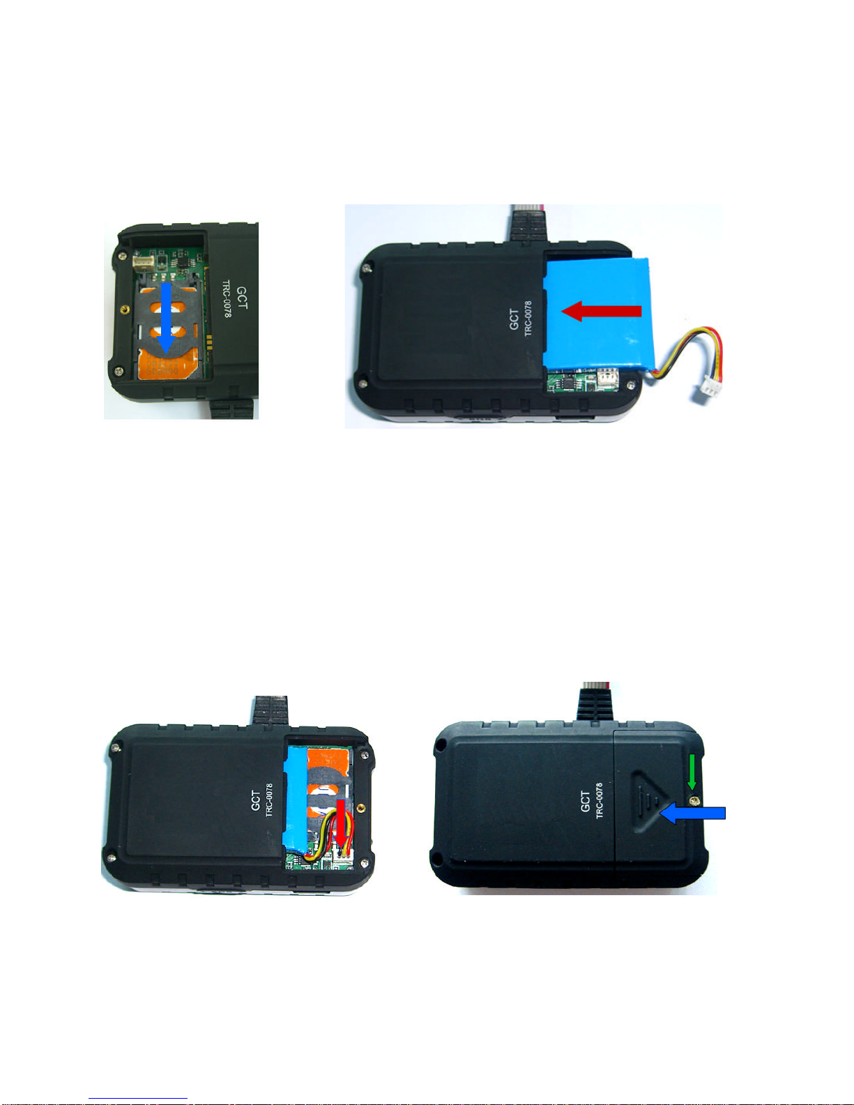
1.4
Install SIM Card and battery:
1.
Remove the back cover of your tracker, as illustrated
above
.
2.
Unscrew the screw and push the battery cover (wi
th an ellipse i
ndent) rightward
to remove it. (Fig.1)
3.
Push the top of the SIM card holder as indicated by the green arrow. (Fig.2)
Fig. 1 Fig. 2
4.
Move
the holder upwards as indicated by the red arrow. (Fig.3)
5.
Insert the SIM card by sliding it into the card holder slot, with the chip module
facing to the connectors, as shown in the picture (Fig. 4)
Fig. 3
Fig. 4
5
6.
Flip down the holder top.
Slide
the holder top downward and let it snap in
completely.
(Fig. 5)
7.
Insert the battery as indicated in (Fig 6)
F
ig. 5 Fig. 6
8.
Carefully c
onnect the battery wires with the connector as indicated (Fig. 7)
9.
Replace the battery cover (blue arrow) and lock with the screw (green arrow)
(Fig. 8)
Fig. 7 Fig. 8

6
2.
General Description
The Tracker can be operated by standard SMS messages
, or via GPRS
. Via an SMS,
the GPS position da
ta can be requested and will be sent back to the requested
party’s
mobile phone via an SMS.
The number and the time sequence of these GPS data
blocks and other parameters are fully programmable by an instruction SMS
.
2.1 Data Format of SMS
Command
Messa
ges:
The data has to comply with a
n exact
format able to be read by the tracker module.
The format is
:
[Password]
-
[mode]
-
[Sub
-
Group1]
-
[Sub
-
Group2]
Password
:
Factory default password is
123
4
Mode
:
Select the operating mode
. This can be a
D
irect comman
d,
S
et
-
up
command
, or
a R
ecall command.
Sub
-
Group1
:
ON / OFF commands; or S
et
-
up
(Initialization)
or
R
equest
group
.
Sub
-
Group2
:
Parameters of the set
-
up group
.
Information like Telephone
n
umbers, setting string of T and C mode, data format for GPS
information (DMS,Google
,Ddec
) etc.
2.2 SOS function:
When the SOS button is p
ressed,
the position data will be sent to a preset phone
number(s). Maximum 8 numbers can be stored which all will be notif
ied if a SOS situation
occurs. These phone numbers c
an be set via a
SMS message sent to the tracker unit.
2.3 Line
-
In and Line
-
O
ut:
(Only applicable for TRC0078)
This tracker has 4 Line
-
inputs,
of
which
2
can be used to detect
switch positions
.
The
other
2 can be used for
rela
tive v
alues such as temperature or fuel
level.
Via the Out
-
put
lines remote equipment can be activated like
an
Alarm or immobilizer
2.4 Geo
-
Fence feature:
This tracker has a geo
-
fence feature
.
If activated,
the instructed party will receive a SMS
when th
e
Tracker unit exits
set boundary area.
2.5 Car Battery connection:
(TRC0078 only)
This track
er has a built
-
in DC
-
DC con
verte
r to allow to
be connected to the 12
-
24V car
battery. This circuitry
is special design to meet the
ISO 7637 requirements
2.6 Bat
tery Low alert:
When the
I
nternal battery is ne
arly e
mpty and reaches a certain
voltage level
the
charge
LED starts blinking and later an SMS
message will be sen
t
to indicate
“Battery Low”
2.7 Stationary or on the move:
(TRE0078 only)
In “Tracking” mode
;
if the position data
equals the 4 previous transmitted positions
(to be
retrieved from SMS
4), the “Tracking” mode will stop, a SMS message will be sent with
extra info in the SMS message
“Stationary Position”
.
2.8 Motion sensor:
The tracker has a moti
on sensor and when switched ON the tracker will automatically
switch
to Track
Mode when
acceleration
is detected twice within 30 sec to 1 minute.

7
2.9 Extra GPS and GSM antenna connections:
(TRC0078 only)
The tracker has extra antenna sockets to allow
c
onnection to external antenna
s
.
Internal
circuitry automatic detects and delivers the power supply to the external antenna
(GPS
)
.
2.10 No GPS data:
If no GPS data can be retrieved from the GPS receiver the unit will transmit the
current
GSM
tower locatio
n “
N
ode” information
.
2.11 Recall history data:
(TRE0078 only)
A
total of 8 previously transmitted SMS messages which
contain position data can be
recalled
via SMS request.
2.12 Last valid GPS position data:
The
“
LAST
”
valid GPS position data can be re
called
via SMS message
.
3.
Operation and Command Modes :
3.1 Direct Commands
3.1.1
Single GPS request mode [S]
Command string:
[Security code]
-
[S]
example: 1234
-
S
In the single GPS request mode only the present GPS information will be sent or if no
GPS
data is available the GSM
“
node
”
info will be sent to requested phone number via
SMS.
3.1.2
Tracking mode [T]
Command string:
[Security code]
-
[T]
example: 1234
-
T
The Tracking
mode is intended to
regularly
check
the
position
of the unit automatically
wher
e
regular update of position is required
, for example, when tracking a stolen vehicle.
The SMS information includes:
GPS coordinates,
GPS date and GPS time
.
3.1.3
LAST valid GPS coordinates [LAST]
Command string:
[Security code]
-
[LAST]
example: 1234
-
LAST
Incas
e no GPS data can be transmitted
(No sa
tellite reception) the GSM cell phone tower
“
Node
” information will be
sent.
With the
“
LAST
”
command however
,
it is possible to
retrieve
the
l
ast
valid GPS coordinates which could
possibly
still
be more accura
te than the
“
Node
”
i
nformation.

8
3.2 ON / OFF
Commands for Modes & Functions
3.2.1
Motion sensor m
ode [M]
Command string:
[Security code]
-
[M]
-
[on]
example: 1234
-
M
-
on
When required, the motion sensor can
be switched ON. It
will
then
automatically s
et the
Tracker in
to the Track
-
Mode
if
movement
is detected
twice within 30sec
-
1minute
.
The
Motion sensor can be switched
OFF
again
via command:
[Security code]
-
[M
]
-
[off]
3.2.2
Geo
-
Fence mode [GEO
]
Command string:
[Security code]
-
[GE
O]
-
[on]
example: 1234
-
GEO
-
on
The Geo
-
fence feature allows the user to set a virtual boundary. The tracker will inform
the
user when
leaving
this boundary. The radius of this boundary
(circle) is set in
default
to
100 meter
s.
The Geo
-
Fence mode van be
switched off via command:
[Security code]
-
[GEO]
-
[off]
3.2.3
Power Saving mode [PS]
Command string:
[Security code]
-
[PS]
-
[off
]
example: 1234
-
PS
-
off
The Power Save mode (PS) allows extended operation of the tracker without recharging
the ba
ttery
.
Battery life however depends on the uses of the
various functions.
The default
setting for Power Save is OFF. If Power Save is switched ON, and the unit is
only
powered from the
internal
battery, it will be switched off for the user
-
defined (“C”
) periods
and will not respond to new SMS commands in those time intervals.
The Pow
er Save mode can be switched on
with
co
mmand:
[Security code]
-
[PS]
-
[on
]
3.2.4
Line
-
Output [LO
]
(TRC0078 only)
Command string:
[Security code]
-
[Lox]
-
[on]
example: 1234
-
L
O
X
-
on
(
X
=1 or 2)
To activate the Line
-
Out, the above command has to be sent. Without
(
X
)
it
will
activate
both
output lines
.
They can be switched of
f
with command
:
[Security code]
-
[LO
x]
-
[off]
3.
2.5
TRACK
mode
[T]
Co
mmand string:
[Security code]
-
[T]
example: 1234
-
T
To switch
on the Track mode when you automatically want
regular position updates
The
Track mode can be switched
OFF
with command:
[Security code]
-
[T]
-
[off
]
example: 1234
-
T
-
off

9
4. Ini
tialization / Programming mode (I)
4.1
Password (Security code)
A password is required to operate the Tracker properly and allow the tracker to accept the
SMS commands.
The factory default password is
“
1
234
”.
It is important to change the
p
as
sword to
o
ne of your own choice (max 8 alpha
-
numeric characters).
Do not forget
your password
, because it can
only
be re
-
set
again to the default
by the factory.
To
change this number the following
command
has to be sent via SMS:
Password
-
I
-
SEC
-
new (α
-
numeric) se
curity number
For example, if you want to change the password from the default “1234” to “4321”, then
you will have send the following SMS to the device:
1234
-
I
-
Sec
-
4321
A SMS will be sent to the caller ID to reconfirm the new setting
4.2 GPS DATA
FORMAT
The default GPS data format is
in Degrees minutes and seconds.
Another format can be
selected
,
like a data format in Degrees decimal.
To
change the default setting the
followi
ng command string has to be sent
via SMS:
Password
-
I
-
GPS
-
DMS
means D
ata in Degrees, minutes and seconds
Password
-
I
-
GPS
-
Google
means URL link for Google Maps
Password
-
I
-
GPS
-
Ddec
means Data in Degrees, decimal
Password
-
I
-
GPS
-
NMEA
-
xxxxx
means a complete line of the NMEA data.
Available lines
for
xxxxx
are:
GP
GGA = Global position Fix data
GPRMC = Recommended minimum data sentence
GPGSA = Overall satellite status data.
A SMS will be sent to the caller ID to reconfirm the new setting
4.3 TRACKING MODE
In T
racking mode
the tracker will send the GPS informa
tion every
3 minutes
(D
efault
setting
is
T=0003) and will repeat this 20 times (R=020)
.
Furthermore the time between
checking for new incoming SMS messages is 10 min (C=010).
Track
-
Mode is normally
used
, for example,
in a chase situation when a car is sto
len and
continuous
trac
k
ing
of
the
route is important.
To enter new time
(T)
number of
repeats
(R)
and SMS check time
(C)
the
following command has to be sent
:
Password
-
I
-
TRK
-
TxxxxRxxxCxxx
Example: 1234
-
I
-
TRK
-
T0003R020C010
A SMS will be sent
to the caller ID
to reconfirm the new setting.
NOTE
:
The time to check for new incoming SMS messages (C) applies when the unit is
operating from the
internal battery
only
,
and Power save mode is active,
with no external
power connected to it.
If connecte
d to a car battery (for example), then the un
it will be
permanently ready to receive
a new incoming SMS
message
, thu
s the “C” time will not
apply.
Restrictions:
SMS checks C within the time T x R will only be carried out if T>2C
See NOTE at the end of thi
s section for expanded information.

10
4
.4
TEL MODE
(Overriding caller ID)
The Tracker can be instructed to send the SMS messages to other telephone number than
the caller ID telephone number of the mobile phone from which the original set
-
up
i
nformation
or request for information was sent. This can be useful in
, for example, a
roaming
s
ituation where the callers ID is not always correctly presented or where the caller
is running out of battery power and
would
like to switch over to
an
other mobile phone.
The
tracker can be instructed to o
verride the default mode to SMS
back to a specified
telephone number by sending the following string:
Password
-
I
-
TEL
-
xxxxxxx
xxxx
xxx
xxxxxx
xx=
<+><country code><phone number>
Any subsequent
instruction sent to the t
racker will override this setting and return to use
the caller ID telephone number, the only
exception is
the
command
:
Password
-
R
-
TEL
4
.5
SOS PHONE NUMBER
S
To enter SOS phone number(s)(max 8) the
following string has to be sent
via SMS:
Password
-
I
-
S
OS#
-
xxxxxx
x
xx
x
xx
xx
x
xxx
=
IDD phone number max 16 digits incl. +
SOS
1
is the 1st
SOS ID
D number, SOS
2
is 2nd etc.
A SMS will be sent to the caller
ID to
reconfirm each new setting and to the new SOS number a SMS will be sent with text info
.
“You
will receive GPS coordinates in case of emergency”
To erase a phone
number
,
just send:
Password
-
I
-
SOS#
-
0
4.
6
GEOFENCE MODE
The geofence mode
creates
a vir
tual circular boundary around
the unit’s location
. The
radius of this
circle can be
set by the following command
:
Password
-
I
-
GEOxx
xx
is the radius x 100m
.
(For TRE0078
xxx
)
For example, “GEO01”, means 100m. This is also the default radius.
(Or GEO001 for TRE0078 which has a 3 digit input)
A confirmation SMS
will be sent to indicate the settings.
4.
7
DEFAULT MODE
The unit can be set to all
the original
default settings
, except the password,
with command:
Password
-
I
-
D
A SMS will be sent to the caller ID to reconfirm the default settings
.

11
5. Recall mode
(T
o
review
system data
)
5.1 GPS DATA FORMAT
A command can be sen
t to the tracker to ask for the
instructe
d GPS data format
information.
Command for this info request is:
Password
-
R
-
GPS
A SMS will b
e sent with GPS data (DMS, Ddec o
r other
)
5.2
TRACKI
NG MODE Settings
A command can be sent
to the tracker to reveal the last set “Track” Mode parameters
T
,
R
and
C
.
Command structure of the “Track” mode settings request is:
Password
-
R
-
TRK
A SMS will be sent to indicate the set pa
rameters of time between GPS transmission
(T),
number of repeats
(R)
and SMS check time
(C)
.
Example
:
TRK
:T0003R020C010
5.
3
TEL MODE
(Overriding caller ID)
Request for telephone number where SMS messages will be sent.
This can be the caller
ID or the new instructed Phone number where the GPS data has to be sent to. Command
structure for “TEL” request is:
Password
-
R
-
TEL
5
.4
GEOFENCE Setting
Reques
t for Radius of Geofence circle. Command structure of the “Geo” req
uest is:
Password
-
R
-
GEO
A SMS will be sent to indicate the Geo
-
fence radius in meters.
5
.5
SOS PHONE NUMBER
S
A command can be sent
to the tracker to reveal the last set SOS phone numbers.
Command structure of the SOS phone numbers request is:
P
assword
-
R
-
SOSx
Where
X
is
position
number of
the
stored SOS phone number.
SOS1
means phone number of SOS1
.
SOS2
means phone number of SOS
2, and so on.
5.6
MOTION SENSOR Setting
To find out if the Motion Sensor is ON or OFF, the following command can
be sent:
Password
-
R
-
M
A SMS will be sent to reveal if the Motion sensor is switched ON, or OFF.

12
6.
Geofence
Goefence is a virtual circular boundary of which the radiu
s can be set by SMS
command.
This feature allows the user to observe if the Tra
cker will remain within a set
boundary (area) or if it will leave this area. This can be important fo
r asset or vehicle
monitoring
with limited
allowed
access within a specified region. Also useful
, for
example,
for the elderly with dementia problems when
living in an elderly ho
me.
When the Geofence is switched ON it will take the tracker
’
s position at that moment to
draw a virtual circle with a specified radius. In default this radius is 100 meter.
The command to switch the Geofence On is:
Password
-
GEO
-
O
N
example: 1234
-
G
EO
-
ON
or
Password
-
GEO
-
OFF
example: 1234
-
GEO
-
OFF
to switch the geofence off.
To set
a different boundary for example with radius of 400 m:
Password
-
I
-
G
EO
04
DEFAULT SETTING:
When no Geofence range is set the tracker will use th
e default setting of 100 meter.
Any other range can be set via the following command:
[security code]
-
[I]
-
[GEO
XX
]
example 1234
-
I
-
GEO
07
Where
XX
is a 2
-
digit figure and represents the radius of the circle in multiples of 100
meter.
Example GEO
07 = 7
00 meters
, or Geo10 = 1000 meters.
STOPPING GEOFENCE:
To turn off
the Geofence mode
,
the following command (SMS message) has to be sent
to the Tracker:
[security code]
-
[GEO
]
-
[off]
example 1234
-
GEO
-
off
To check the Geofence setting
,
a
SMS message has to be sent to the
tracker as follows
:
Password
-
R
-
GEO
The tracker will send SMS with the
requested information
.
Example:
“GEOFENCE is set to 400m”
13
7
.
Line
-
Inp
uts
.
(TRC0078 only)
The TRC0078 is equipped with an external connector for
external power
connections
(like
a car battery)
and Line
-
In/Line
-
out terminals to connect to remote systems and/or
switches.
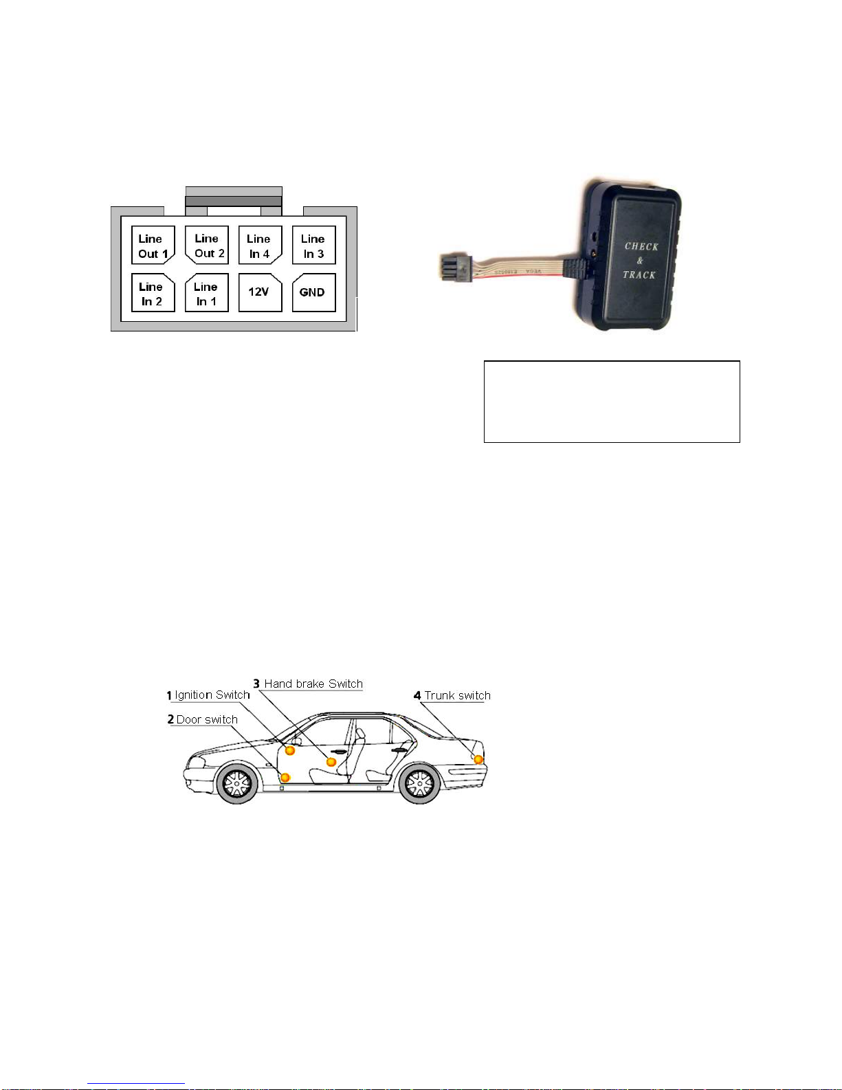
The TRC0078 has a connector with 8 pin terminals.
4 pins for Inputs
2 pins for Outputs
1 pin for Car battery voltage (+)
(+12
-
24V)
1 pin for ground
The 4
L
ine
-
In terminals can detect or register events which will trigger the Tr
acker to send
a SMS “Alert” message
,
or
it
can indicate a
voltage
level
as % of a reference voltage 3.3V
The Line
-
In terminals are
set for the following registration:
7.1
“
ABSOLUTE
”:
Line
-
In
1
and Line
-
In
2
are set to register ABSOLUTE events.
Lin
e
-
Input
1
& 2
are
set
to send an “Alert” message
when the input voltage changes
from 0V to +Vb
or from +Vb to 0V
Input 1 and 2 can be used
, for example,
to detect a switch function like a door switch,
ignition switch, handbrake switch or trunk switch.
Possible switch connections
In the event when one of these switches is activated the Tracker will be t
riggered and
will automatically send a SMS
“Alert” message.
Depending on which switch is activated
it will indicate in the S
MS the switch number.
For example if the Brake switch is connected to line
-
input 2, the SMS will indicate
the
number.
Example: “Alert 2”
View at
t
he Pins
B
lack
=
ground
Orange
= Line
-
In3
Red
=+12
-
24V
Yellow= Line
-
In4
Brown=Line
-
In1
Blue
= Line
-
Out2
White =Line
-
In2 Green=Line
-
Out1

14
7.2
“
RELATIVE
”:
Line
-
In
3
and
4
are set to register RELATIVE events.
Both inputs measure the i
nput volta
ge via an A/D converte
r and register the vo
ltage level
as % of a
reference voltage of 3.3V
.
In the Relative mode it is possible to measure fluctuating parameters and the delta of
these fluctuations, like Temperature or Fuel Levels. If for example the inpu
t voltage is
1.32 volt th
e
SMS
message will indicate:
Li3= 40%.
The Line
-
Input status is indicated in
each GPS coordinate message.
8.
Line
-
Outputs
(TRC0078 only)
The TRC0078 has 2 line
-
Out terminals which can be used to
remotely
control
systems.
Elect
rical specification of Output terminals:
Max. Output voltage:
24V
Max. Sink Current:
<500mA
T
wo Independent controllable Outputs can be used to
control the drive circuitry of a
number of remote system
s
like:
8.1 Commands related to
the Output Lines:
ACTIVATE
/
DEACTIVATE
:
To activate the Line
-
Outputs the following command has to be sent:
[security code]
-
[LO
X]
-
[ON]
(
Where “
X
”
= 1 or
2
)
An SMS will be sent to confirm the setting:
“LO
1
is active
”
or
“Lo2
is
activ
e
”
[security
code]
-
[LO
X]
-
[OFF]
(
Where “
X
”
= 1 or 2)
A reply SMS
confirm
s
the setting:
“LO
1
is not
activ
e
”
or
“LO
2
is not
activ
e
”
STATUS Information of Line
-
Out
:
The status of the Line
-
outputs is indicated in every GSM coordinate message
The Tracker will send
the
status as follows:
“LO1
-
ON
”
or
“LO1
-
OFF
”
“LO2
-
ON
”
or
“LO2
-
OFF
”
Control immobilizer circuit for Start
-
Motor
Control Alarm System
Tracker with
2 Line
-
O
ut Control lines
15
9.
Timing criteria
The Default
timing
programming
settings are:
T
0003
R
020
C
010
The meaning of these parameters are as follows:
T
=
Time between each SMS message
with G
PS coordinates
that the device will send
when it is
in
the “
Tracking
”
mode
.
R
=
Number of
times the
GPS
position
SMS messages
is sent while in
“
Tracking
”
mode
.
C
=
This is the t
ime
delay
between
Checking for any
new SMS messages when
operating from
th
e
internal
b
attery only
, and in Power Save mode
.
9.1 O
perating from
I
nternal
battery
only, with
No
external power
connected.
Power
Save
Mode
-
OFF
:
If Power saving mode is switched
OFF
the SMS messages will be process
ed
immediate
ly
,
but as a consequence the
battery will last much shorter.
With
the
700mA
internal battery, it will only last about 10
-
12 Hrs.
16
NOTE
: Expanded information on
Parameter setting
s
for Tracking
and
Power Save modes
:
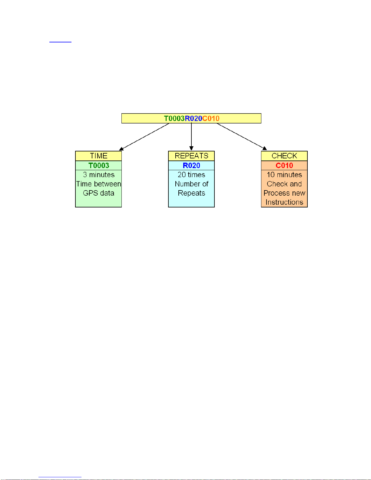
The parameter forma
t is: T0003R020C010 (Default)
Password
-
I
-
TRK
-
TxxxxRxxxCxxx
Example: 1234
-
I
-
TRK
-
T0003R020C010
The first block in this string indicates the time
between position reports f
or
the
Track
ing
Mode
.
T
he default time between transmitted SMS cont
aining the GPS data is 3 minu
tes.
This time can be changed to a number
between 3 to 9999 minutes.
For e
xample
if you
want
a SMS with updated GPS
i
nformation
every 30 Minutes while it is in Tracking mode,
it should be
set as T0030
.
The second block
i
ndicates the number of repeated position messages
.
When
this number
is reached the trac
ker will stop the Track
-
Mode
.
Default in Track Mode is
R020 and can be
changed to any number from 1
-
999.
If this number is excessive, it may be too large for
the ba
ttery life.
The third block
is only applies if the device is operating from the internal battery, and with
Power Save mode ON. It i
ndicates at what time intervals the tracker will check if a SMS
was
sent with
a new instruction.
This is also valid if t
he time
interval between GPS position
data is large while it is in Tracking mode. The condition to have a check between GPS
data messages when tracking mode is active, is
T >2C.
The time can be set between 3
-
999 minutes
17
9.2
Powe
r Save
M
ode
-
ON
.
Operating from internal battery
only,
with
NO
external power connected
:
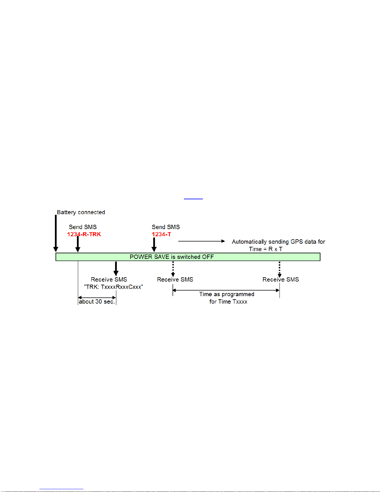
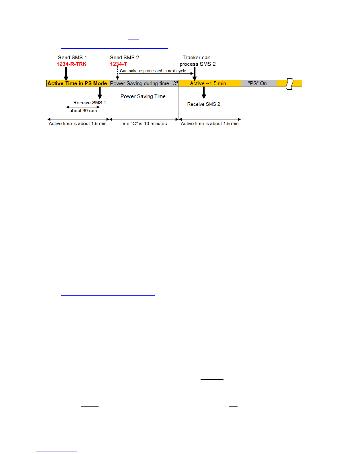
In above example a message
1234
-
R
-
TRK
is sent in the active Time (about 1.5 min.) of
the Tracker and a response message will
normally
be received in about 30 seconds
.
(Depending on the mobile network provider)
The second
SMS command
1234
-
T
can only be processed in the next active time
after
the Power Save period
,
and the entire device is turned off for
10
minute periods (Or
whatever the “C” time is required by the us
er)
.
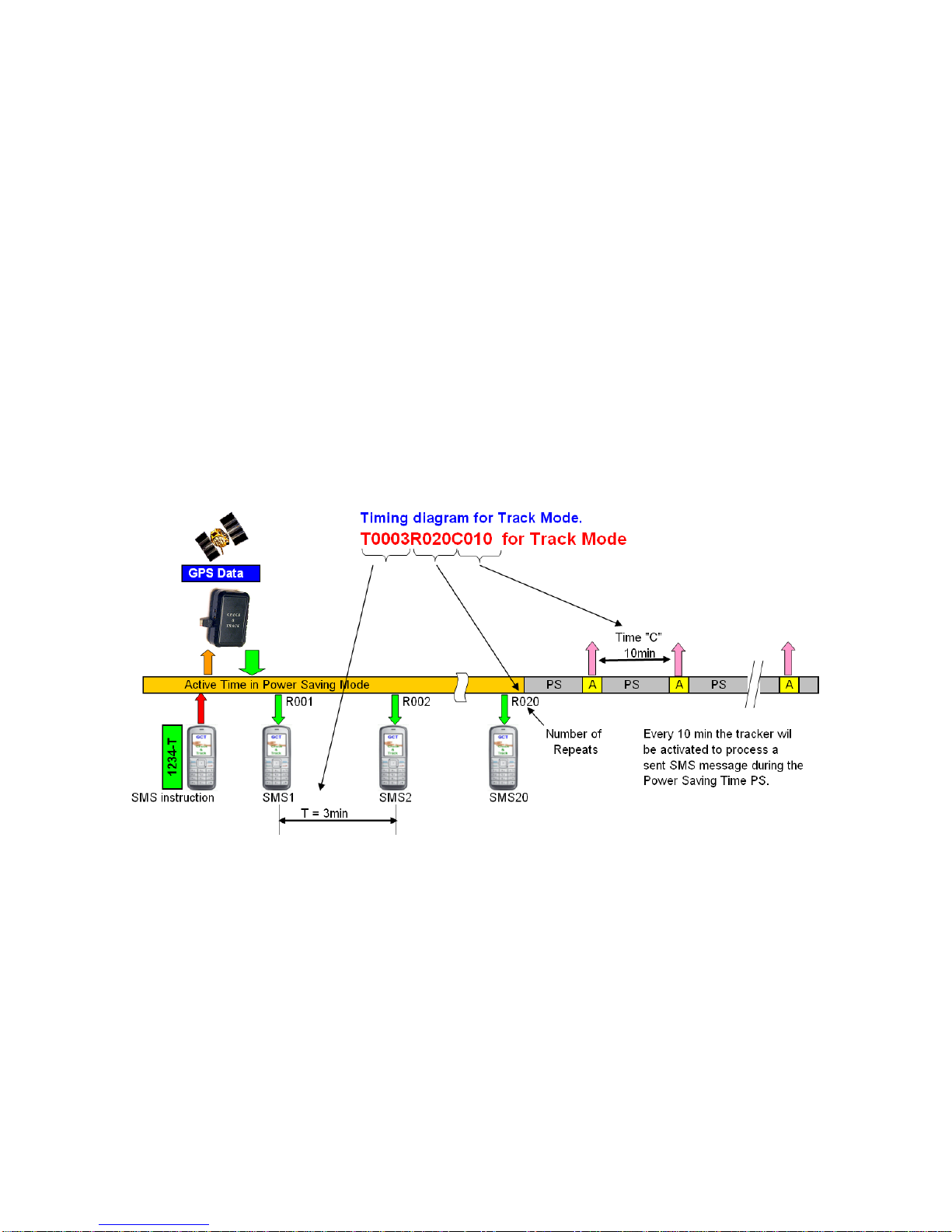
NOTE:
If
the
“
T
”
time in the T
rack
mode is set to <10 min the tracker will be able to
receive instruction
SMS
messages directly for the time T x R. If time is >10 min the
tracker will go in
to
Power Savings (PS) and a SMS sent in that period will on
ly be
processed after the check time “C” is finished. See example above.
NOTE:
Before switching to PS mode ON it is advised to run the tracker in PS
-
mode
OF
F
for about 15 minutes to al
low the tracker to build
-
up the Ephemeris and
Almanac of
the satellit
es and after all new parameters are changed to your
preferred settings.
NOTE: For a general
idea of how
Power savin
g mode saves battery life, when
a SMS is
sent with GPS coordinates
every 15 min (e.g. Tracking mode activated with a “T” time of
15 min), t
h
e
internal
bat
tery will last about one week.
Depending on other parameter
settings the battery
life could
even last for
months
.
9.3
External power connected
with Power Save
Mode
-
ON
:
(TRC0078 only)
The device will be able to receive SMS messages
at all t
imes
, and they will be
processed immediately while within the GSM reception area. O
ther
features
,
like the
internal
GPS
,
goes into standby mode to save
the
battery power of
the
external power
source
. It
will be activated by the required
mode you want to
p
re
-
program. Example
–
Motion sensor ON and Power save ON: The tracker will be able to receive SMS
commands at all times, but will only switch on the GPS when motion is detected, or
when you request GPS position.
NOTE:
It is important to note that there is
a difference in how the Power Save feature
works, depending on if it is connected to an external power source, or if
it is only
operating from the internal battery. If connected to an
external
power source, the device
will be able to receive new SMS comma
nds at all times.
In other words, the “C” timing is
not valid at all, as the GSM feature remains permanently active in this case.
If operating
ONLY
from the internal battery
, the
n the
device will
not
be able to receive
new SMS commands while it is in stan
dby during the “C” times programmed if Power
Save is ON.
18
10.
Track Mode
Command String:
<Password>
-
T
for Track Mode
example
:
1234
-
T
The Track Mode is important in cases where a regular
position check is important,
f
or
example
,
when your vehicle
is
stolen
and you want to track its route
.
Track mode is also
activated by the Motion sensor, or by geofencing if required.
The Default
programming
settings are:
T
0003
R
020
C
010
The meaning of these parameters are as follows:
T
=
Time between each SMS
message
with GPS coordinates
that the device will send
while it is in the “Tracking” mode
.
R
=
Number of
times the GPS position
SMS messages
is sent while in “Tracking” mode
.
C
=
This is the t
ime
delay
between
Checking for any new SMS messages when
op
erating from the internal battery only, and in Power Save mode.
10.1
Power Saving Mode ON
, internal battery only
:
10.2
Po
wer Saving Mode
OFF:
If the Power Saving Mode is switched OFF the tracker will always be in an active state.
This means that the GPS coordinates will b
e available as in warm stage
within about
12
seconds.
The parameters for T and R are still va
lid and can be set according your own
requirements. The parameter “C” however is not valid any more.
19
11. GPS
accuracy and time to Fix
and SMS Delays
11.1
Accuracy
P
lace the tracker in a position to allow the best possible open sky view.
Ob
struction can
a
ffect the time and accuracy of the GPS data.
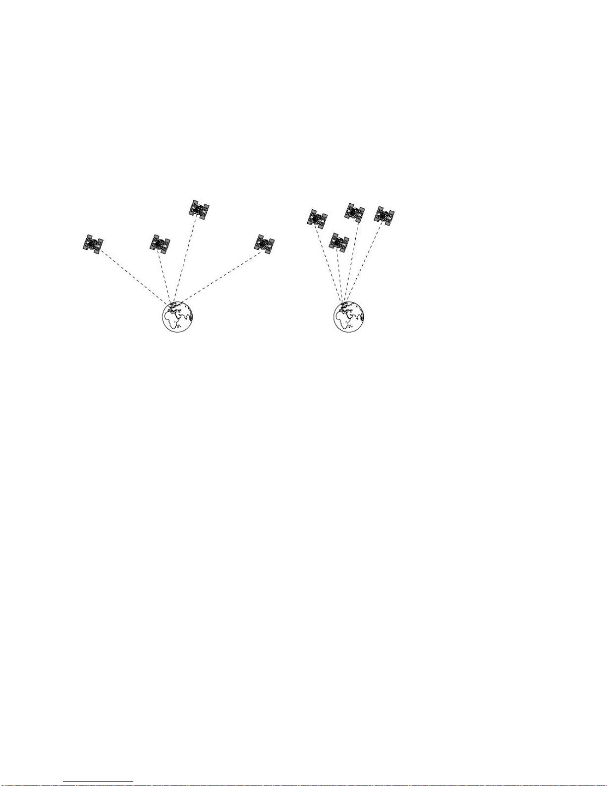
The accuracy of the GPS position
d
epends on a number of factors
. First of all
, the number of satellites from
which signals
can be received by the tracker. More satellites will give a better accuracy.
The
number
of the satellites
received
is an important factor.
1
-
Better Accuracy
2
-
Less accurate
Further more
,
a
clear sky view will give better results than a sky view which is
obstructed by buildings and/or trees. Accuracy according reception of signals as shown
in picture 1 can
sometimes
be within a few me
ters.
11.2
Time to Fix, Time of acquisition
of GPS data
Apart
from the points listed under 11.1
, the time of a 2D or 3D fix depends on
the
received signal strength of the satellites.
I
t is therefore important not to put obstacles
between the tracker and
the open sky.
For example, a
thick jacket over the tracker will
influence the sensitivity and will result in longer times to acquire the satellite data.
In
normal operation condition the time for 3D Fix is around 40 seconds
(Cold start) and
between 6
-
20 se
c. in
a “
warm
”
start condition.
11.3
Time delays due to
GSM
Network
congestion
Depending on the GSM network traffic, SMS instructions and/or data transfer can be
very quick. However
,
due to heavy traffic congestion these messages can
sometimes
be delaye
d.
It is recommended if this kind of delay happens to wait for awhile before
resending
a
SMS message.
It
is strongly recommended to use SIM cards in your mobile phone
and
tracker
fro
m the
same telephone company to
avoid late
ncy in the SMS hand
ling
.
M
es
sages
between
different network providers
are handled differently
an
d
can
sometimes
cause
excessive
delays.
When very long latencies occur please contact the supplier for special settings
to minimize this problem

20
12.
Examples
on
how to
put the coordinates in a Map program
12.1
Google Maps (Satellite Image) Input via Degrees
-
Minutes
-
Seconds
12.2
Google Maps I
nput:
Degrees
-
Minutes
-
Seconds
Table of contents


