GDC Group 230 VAC User manual

N177/R04(08. 03. 10)
DIGITAL THERMOSTAT

DIGITAL THERMOSTAT (230 VAC)
SUMMARY
• OPTIONS SELECTION
On the inside of the rear side of the thermostat, there are two switches which enable the thermostat to be
set according to your preferences:
→Temperature in °C or °F and the Early Start function – what is known as Fuzzy logic (it’s a self-
learning thermostat).
• SETTING THE TIME AND DAY
Set the time and day using the DAY, HOUR and MIN buttons.
• SETTING THE DAY (COMFORT) SETPOINT TEMPERATURE
Select the required setpoint temperature using the or arrow. Press the button and hold it for 2 –
3 seconds until the symbol appears on the display.
• SETTING THE NIGHT (ECONOMY) SETPOINT TEMPERATURE
Select the required setpoint temperature using the or arrow. Press the button and hold it for 2 – 3
seconds until the symbol appears on the display.
• SETTING THE VACATION SETPOINT TEMPERATURE
Select the required setpoint temperature using the or arrow. Press the button and hold it for 2 -3
seconds until the symbol appears on the display.
• OPERATING MODES
To select the operating mode, use the Mode/Return button.
AUTO: Programmes operate in this regime. The or arrow will show the setting of the temperature
and can temporarily override the programming up until the next programme.
MAN: This regime maintains the set temperature. The temperature setting can be changed using the
or arrow.

INSTALLATION
The thermostat has two temperature sensors. The first one, installed under the cover in the device,
reads the ambient (air) temperature. The second one, installed in the floor, limits the floor temperature.
The installation of the thermostat should be carried out by an electrician (a person qualified in IEE
wiring regulations or standards specific to your geographical area).
The thermostat needs to be connected on a circuit equipped with a fuse or a circuit breaker in a
standard electrical box.
For the placement of the thermostat, choose an inside wall, approximately 1.5 m above the floor in a
place with free air circulation. Do not place the thermostat in a place where there is direct sunshine or
in places where its function could be directly affected by heat created by the operation of certain
appliances (television, fridge etc.).
Do not install the thermostat in locations where there are air drafts (the top of a staircase, an air outlet),
dead air spots (behind a door), in direct sunlight or on walls where there are chimneys or stove pipes.
BEFORE INSTALLATION, TURN OFF THE POWER TO THE HEATING SYSTEM
USING THE PROTECTIVE ELEMENTS IN THE POWER PANEL TO AVOID
INJURY FROM ELECTRIC CURRENT.
Keep the air vents of the thermostat clean and free from obstructions.
PARTS INCLUDED
- one (1) (230 VAC) thermostat
- one (1) temperature sensor with a 3 meter lead (can be shortened)
- one (1) wall plate
1. Installation of the thermostat
Before installation, turn off the power to the heating system on the main power panel in
order to avoid injury from electric current.
Unscrew and remove the front part of the thermostat from the base plate. The screw
cannot be unscrewed completely.
Thermostat with a wall plate
Before making the connections, make sure that the base plate of the thermostat covers
the electrical box completely. If not, insert the wall plate between the thermostat and
the box.*
* The wall plate can also be used for aesthetic reasons.
Connect the wires.
(see section 1.1)
Connect the sensor.
(see section 1.2)

Secure the base of the thermostat to the electrical box (KU, KP 68).
Set the switches which are located at the back of the front part of the thermostat
before inserting the front part back into the base (see section 1.3).
Affix the front part of the thermostat to the base using the built-in screw.
You can turn the power back on now.
1.1 Connection

Connection diagram for the AC 130-03 filter
The snubber must be connected into the circuit of the thermostat if the thermostat
switches induction load – e.g. in the case of connection of the load via the contactor.
Connect the snubber as close as possible, if possible directly, at the connectors of the
contactor coil.
Please contact GDC Group Ltd using the address details at the end of this instruction to obtain
the snubber using part number 3509002.

Connecting the temperature sensor
Connect the wires of the temperature sensor to the terminals on the rear side of the thermostat (no
polarity needs to be respected).
Note: Do not install the floor probe immediately next to a heating element. Insert the probe between
the heating cables (it mustn’t touch them), approx. 20 cm deep into the heating area, as close to the
surface as possible. The cable of the temperature sensor mustn’t lie across the heating cables.
Setting the maximum temperature of the floor
Check the set temperature of the floor during the installation of the floor sensor. The recommended
value is 27–33 °C (depending on the type of room). To adjust the setting of the maximum floor
temperature, press the adjustment button (you can see the position of the button in the picture) using a
pointed object and the or arrows.
1.2 Configuration of switches
a) Early Start function, known as Fuzzy Logic
The thermostat has a built-in function which enables the calculation of the optimum
time to start the heating system to achieve a desired temperature at the programmed
time. Set the E.S. (No.1) switch to “ON” for the activation of this function.
b) Temperature in °C or °F
The default configuration of the thermostat is in °C. If you want to change the setting to °F,
move switch No. 2 up. If this change is made, don’t forget to change the comfort and
economy heating settings as well.
POWERING UP THE THERMOSTAT
When the thermostat is switched on for the first time, the
display will show the time 0:00, the temperature, and the
manual mode ( ) symbol. If the thermostat is defective or
doesn’t comply with the instructions, other information may
appear.
If the temperature sensor is defective, or if the temperature is
lower than 0 °C or higher than 60 °C, the message LO or HI
will appear on the display. If the LO message is displayed,
the heating indicator will also appear and the relay will be
closed (the current is going in the load).

OPERATING MODES
The thermostat has two (2) operating modes.
MAN – manual mode ( )
This mode enables the maintenance of a constant temperature.
1. To activate this mode, press the Mode/Return button. The symbol will appear.
2. Set the desired temperature using the or arrows, or use the settings which are programmed for day,
night or vacation operation ( , , ).
AUTO – automatic mode ( )
This mode executes your own programming.
To activate this mode, press the Mode/Return button. The symbol will be displayed. The and symbols
indicate which temperature setting is used. Also, the number of the programme will be shown.
Vacation function
This function sets your thermostat to your specified vacation temperature.
If you are to be absent for a longer period, set the vacation heating using the button. The display will show the
symbol. The temperature will remain at this setting until it is returned to the normal operating mode using the
Mode/Return button. If you wish to return to the programmed setting immediately, press the Mode/Return
button.
PROGRAMMING
Programming the time and day
1. Set the time using the Hour and Min (minute) buttons.
2. Set the day using the Day button.
Programming the comfort, economy and vacation settings
The comfort temperature is the temperature that you wish to be set during the day, the economy temperature
is set for the night or for periods when you are at work, and the vacation temperature is set for a longer period
of absence.
Programming:
a) Select the desired comfort temperature setpoint using the or arrows and press the button (hold
for about 3 seconds). The symbol will appear on the display.
b) Select the desired economy temperature setpoint using the or arrows and press the button (hold
for about 3 seconds). The symbol will appear on the display.
c) Select the desired vacation temperature setpoint using the or arrows and press the button (hold
for about 3 seconds). The symbol will appear on the display.
d) Press the Mode/Return button to exit this function and return to the normal operation mode.

Day by day schedule programming
The thermostat allows the setting of 4 different programmes for each day of the week. There are no pre-set
programmes. The programs are designed in such a way that they perfectly adapt to your life style. The principle
is very simple. For each day, enter the time when you wake up (P1), the time you leave for work (P2), the time
you arrive back home (P3) and the time you go to bed (P4).
Programme Mode Time
comfort Wake-up time
economy Leaving time
comfort Return time
economy Bed time
For economical operation, you must lower the temperature for a period at least 2 times longer than the delay
required to bring the temperature back to the comfort level.
Example: If your system takes one hour to get from the economy temperature to the comfort temperature,
nothing is gained by lowering the temperature for a period shorter than two hours.
a) Programming your schedule
1. Press the Pgm button to access the programming mode.
2. Press the Day button and select the day to be programmed. You can select all of the days of the week at
the same time by pressing the Day button for a period of 3 seconds.
3. Press the Pgm button and select programme 1, 2, 3 or 4.
4. Set the time using the Hour and Min buttons.
5. When you have finished programming, exit the function by pressing the Mode/Return button.
b) Erasing a programme
Select the programme using the Pgm and Day buttons and press the Clear button. If the programme is not active,
the time field will display -:-.
c) Example 1: Setting of the comfort temperature from 7:00 to 22:30
Setting of the economy temperature from 22:30 to 7:00
Identical setting of programmes for all the days of the week
Prog./day Monday Tuesday Wednesday Thursday Friday Saturday Sunday
PROG. 1 7:00 7:00 7:00 7:00 7:00 7:00 7:00
PROG. 2 --- --- --- --- --- --- ---
PROG. 3 --- --- --- --- --- --- ---
PROG. 4 22:30 22:30 22:30 22:30 22:30 22:30 22:30
1. Press the Pgm button to access the programming mode.
2. Press the Day button and hold it for 3 seconds to select all the days of the week.
3. Press the Hour button and enter 7:00 into Prog. 1 (☼)
4. Press the Pgm button three times to select Prog. 4 (☾) and then press the Hour and Min buttons and
enter 22:30.
5. Press the Mode/Return button to exit this function.

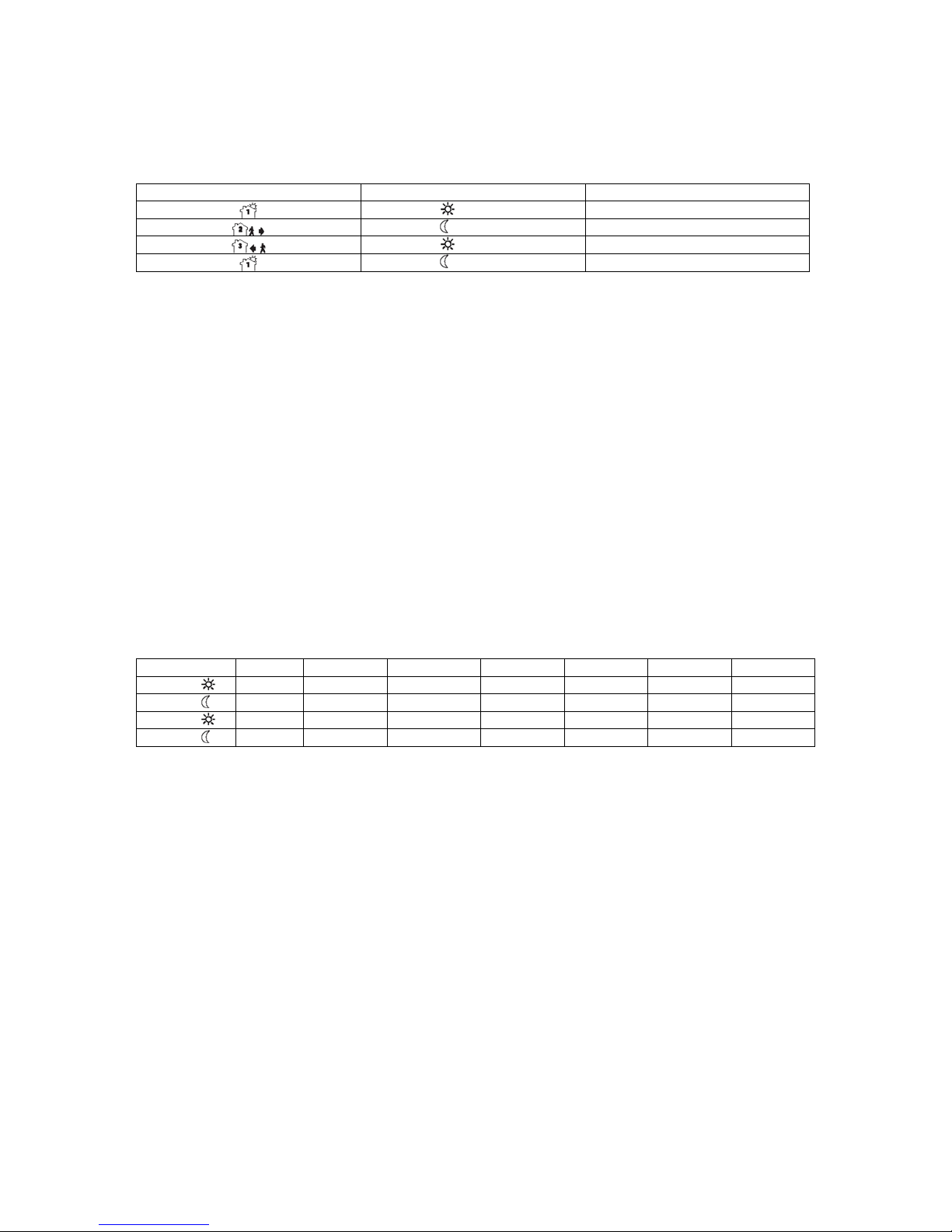
d) Example 2: Setting of comfort temperature
Monday to Friday from 6:15 to 8:15 and from 17:00 to 22:00,
on Saturday and Sunday from 7:30 to 23:00
Prog./day Monday Tuesday Wednesday Thursday Friday Saturday Sunday
PROG. 1 6:15 6:15 6:15 6:15 6:15 7:30 7:30
PROG. 2 8:15 8:15 8:15 8:15 8:15 --- ---
PROG. 3 17:00 17:00 17:00 17:00 17:00 --- ---
PROG. 4 22:00 22:00 22:00 22:00 22:00 23:00 23:00
Note: It is faster to programme all days in the same way and then change the days which are different.
1. Press the Pgm (programming) button to access the programming mode.
2. Press the Day button and hold it for 3 seconds to select all the days of the week.
3. Press the Hour and Min buttons and enter 6:15 into Prog.1 ( ).
4. Press the Pgm button and select Prog.2 ( ) and then record the time 8:15 using the Hour and Min
buttons.
5. Repeat step 4 to set Prog. 3 (17:00) and Prog. 4 (22:00).
Note: When making modifications, always check that you are in the right programme.
Modification of Saturday and Sunday settings
6. Press the Day button and select SA (Saturday) or SU (Sunday).
7. Press the Pgm button to select Prog. 1 ( ) and record the time 7:30 using the Hour and Min buttons.
8. Press the Pgm button to select Prog. 2 ( ) and then erase it by pressing the button Clear.
9. Press the Pgm button to select Prog. 3 ( ) and then erase it by pressing the button Clear.
10. Press the Pgm button to select Prog. 4 ( ) and record the time 23:00 using the Hour and Min buttons.
11. Press the Mode/Return button to exit this function.
Memory back-up
In the event of a power failure, an internal circuit will maintain the programming and the time. If the
power failure exceeds two hours, only the time will need to be set again.
Manual – for a short-term change in temperature
This function allows a temporary change of temperature in the automatic mode. Simply select the
required temperature using the or arrows or select the comfort or economy setting which you have
programmed, using the or buttons. This temperature will be maintained until the beginning of the
next programme. If you wish to immediately return to the programmed setting, press the Mode/Return
button twice.
Use of only one probe
The thermostat is equipped with two temperature probes. The floor probe (a cable sensor) is detachable
but the thermostat is not able to function in a standard way without this sensor. You can put the
individual sensor out of operation by setting the maximum temperature in the programme, which cannot
be practically achieved. For example, when using the floor temperature sensor only, set the night
(economy) temperature to the lowest possible value, +5 °C. During this time, the thermostat won’t
switch on the heating because the temperature in the room will not drop to +5 °C during normal
operation. For the time when we want the thermostat to switch on the heating, we’ll set the day
(comfort) temperature to the highest possible value, +30 °C, as it is expected that this temperature will
never be reached in the room. We’ll set the desired floor temperature on the floor sensor and the
thermostat will work as an on/off switch. On the other hand, when the temperature on the floor sensor is
set to +40 °C and the room sensor has the standard programme and temperature settings, we’ll achieve
taking the floor sensor (probe) out of operation, as this temperature will never be reached during
ordinary heating.

TECHNICAL PARAMETERS
Model: TH132-AF
Supply: 230 VAC 50 Hz
Load
- resistive: 16 A max.
- inductive (necessitates use of SNUBBER AC 130-03): 2 A max.
Power: 3680 W at 230 VAC
Approvals: EN60730-2-9
EN50081-1 / EN50082-2
Display range: 0–60 °C
Setting range, ambient temperature: 5–30 °C
Setting range, floor temperature: 5– 40 °C
default setting: 20 °C
default setting: 18 °C
default setting: 10 °C
Storage: -20 to 50 °C
Software: ClassA
Controller: Electronic
Protection: Class 2
Protection degree: IP20
Automatic action: Type 1B
Environment: Normal pollution level
Programming protection: Memory back-up
Clock protection: 2 hours
Dimensions (w × h × d): 79 × 83 × 13 mm
The terminals are designed for a wire with a cross-section of 0.33 to 3.1 mm².
WARRANTY
For normal use, a 2-year warranty from the date of purchase from an authorized seller is
provided for flaws in the material or which occurred during the manufacturing of this product.
The warranty doesn’t include transportation costs or costs of installation, uninstalling and re-
installation. The warranty doesn’t apply to products which have been damaged by improper
use.
In the case of any questions regarding the installation or programming of this product, please
call our technical assistance helpline.

THERMOSTAT FAULT DESCRIPTION FORM
To speed up the proceedings, please specify the fault.
Description of the switched load, wattage (for example: heating mat, 1 400 W):
Put a cross next to the fault; you can also add details.
The thermostat is attached to a power source, the display is not lit.
The thermostat is attached to a power source, the display is lit, but it doesn’t react.
The thermostat is set and placed correctly, the target temperature is not achieved but it doesn’t switch
on.
The thermostat is set and placed correctly, the target temperature is achieved but it doesn’t switch off.
The thermostat sets itself to zero when the tariff changes from high to low.
Other fault:
If you wish to make a complaint, please copy this sheet and enclose it with the thermostat.
SERVICE
GDC Group Ltd
Millbrook House
Grange Drive Customer Services: Tel: 0845 604 2330
Hedge End Fax: 01489 773050
Hampshire SO30 2DF
Republic of Ireland: Tel: 01 8424833
Table of contents
Popular Thermostat manuals by other brands

Mars
Mars HEAT CONTROLLER IR Wireless Thermostat user manual

Honeywell
Honeywell RLV4305 owner's guide

HOTOWELL
HOTOWELL HTW-MT06 Series Installation and operation manual

Energotech
Energotech EnergoControl T60 Series user guide

Bpt
Bpt TH/500 installer and user manual

Johnson Controls
Johnson Controls S1-THXU280W Technical guide