GDC AIB-2000 User manual

USER MANUAL FOR
AIB-2000 IO (INPUT-OUTPUT) BOX
April 01st, 2021

-1 -
April 01st, 2021
USER MANUAL FOR AIB-2000 IO (INPUT-OUTPUT) BOX
User Manual
TABLE OF CONTENTS
TABLE OF CONTENTS
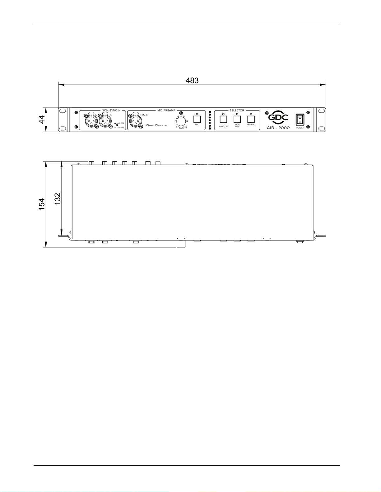
1DIMENSIONS.................................................................................................3
2SPECIFICATIONS .........................................................................................4
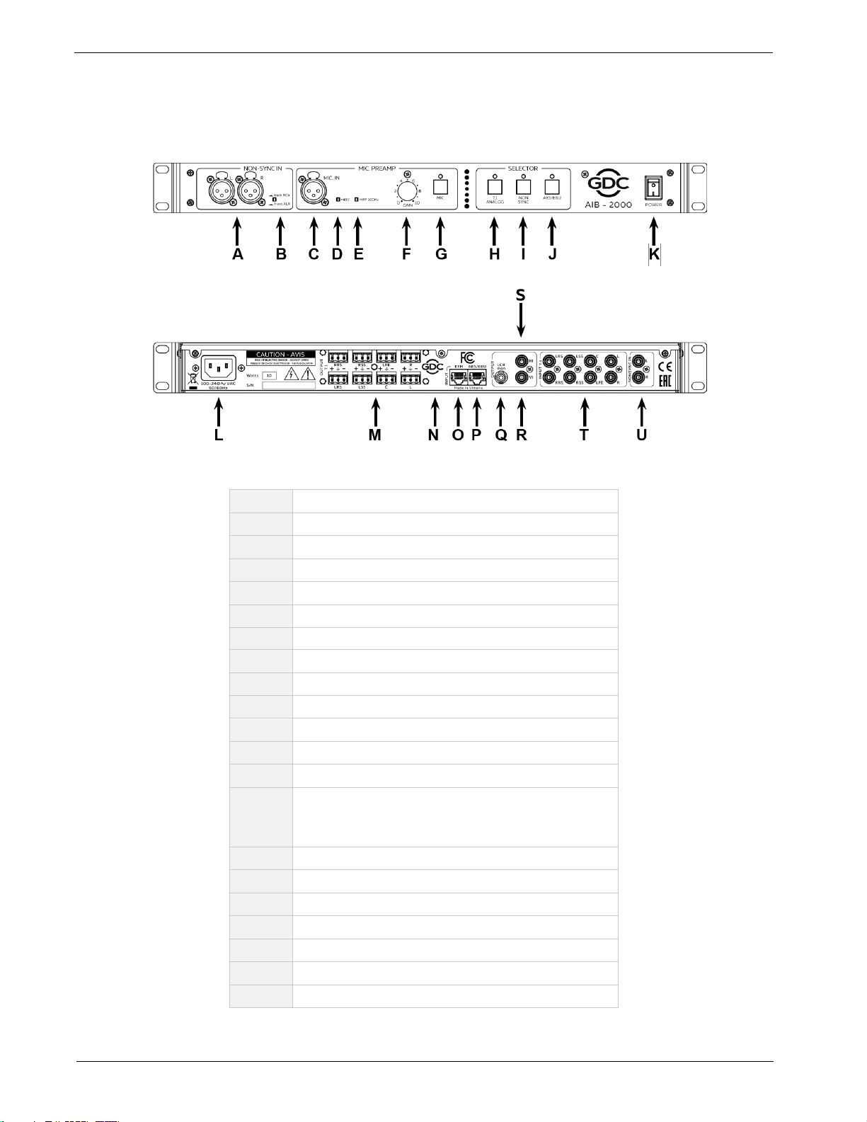
3FRONT AND REAR PANELS........................................................................5
4ROUTING DIAGRAM.....................................................................................6
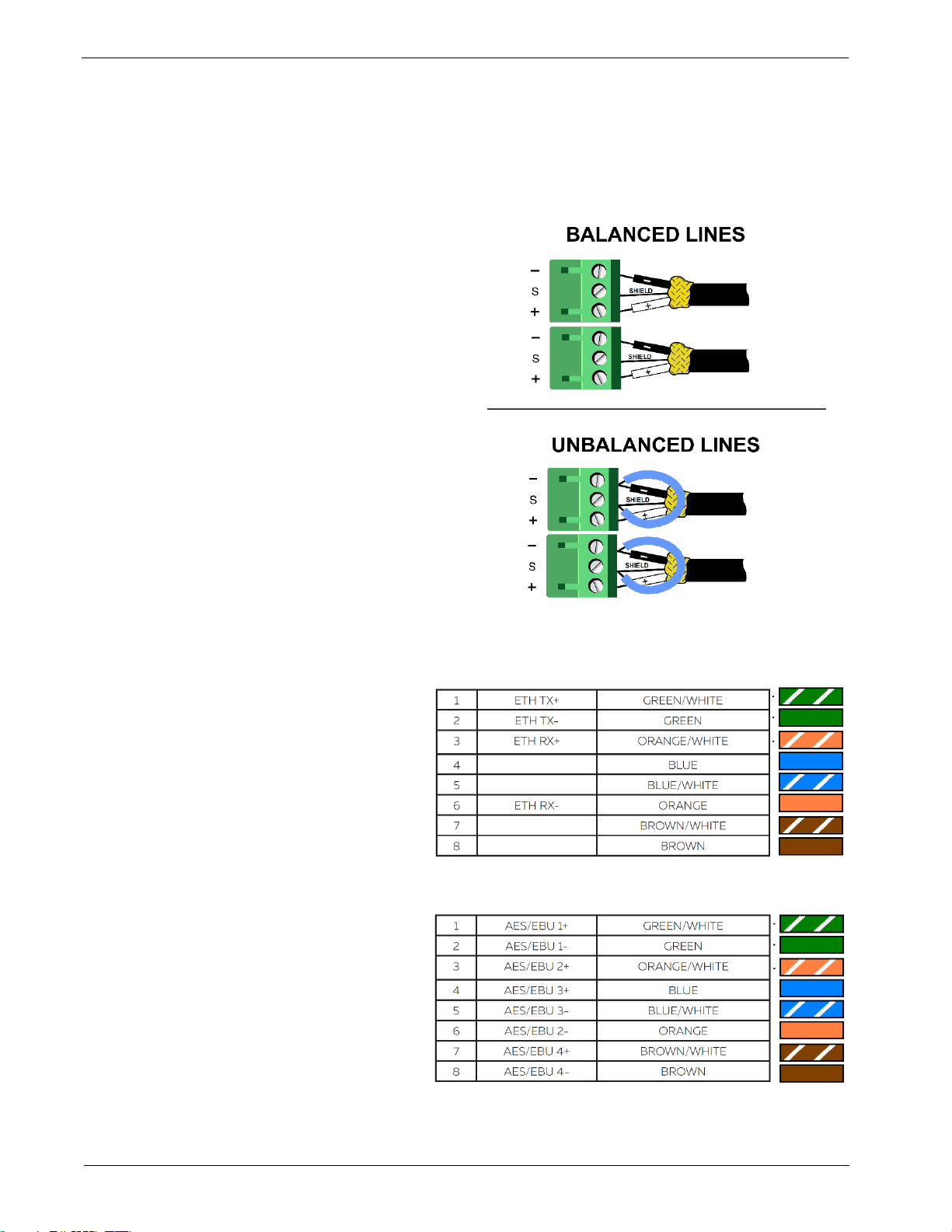
5ETHERNET/ AES/EBU/ ANALOG OUT CONNECTION...............................7
6SAFETY INSTRUCTIONS .............................................................................8
7REGULATORY INFORMATION..................................................................10
8INTRODUCTION TO AIB-2000....................................................................11
8.1 About the AIB-2000...................................................................................................... 11
8.2 Unpacking and Checking for Shipping Damage ...................................................... 11
8.3 Packing Material .......................................................................................................... 11
9AIB-2000 CONNECTIONS...........................................................................12
9.1 Installation.................................................................................................................... 12
9.2 AC Mains Supply ......................................................................................................... 12
9.3 Routing Diagram.......................................................................................................... 12
9.4 Front Panel................................................................................................................... 13
Front NON-SYNC IN...........................................................................................................13
MIC INPUT ..........................................................................................................................13
SELECTOR.........................................................................................................................13
9.5 Rear Panel .................................................................................................................... 14
7.1 Output...........................................................................................................................14
AES/EBU in.........................................................................................................................14
Ethernet in..........................................................................................................................14
LCR mon.............................................................................................................................14
H/I and V/I ...........................................................................................................................14
7.1 Input..............................................................................................................................15

-2 -
April 01st, 2021
USER MANUAL FOR AIB-2000 IO (INPUT-OUTPUT) BOX
User Manual
TABLE OF CONTENTS
Rear NON-SYNC IN............................................................................................................15
10 AIB-2000 REMOTE CONTROLS.................................................................16
11 AIB-2000 WEB INTERFACE.......................................................................17
11.1 Default Access Credentials ........................................................................................ 17
11.2 Resetting AIB-2000 to Default Factory Settings....................................................... 17
11.3 Accessing the Web Interface...................................................................................... 18
11.4 About the AIB-2000 Web Interface............................................................................. 18
Control................................................................................................................................18
Config →IP config.............................................................................................................19
Config →Misc config........................................................................................................20
Config →Reboot ...............................................................................................................21

-3 -
April 01st, 2021
USER MANUAL FOR AIB-2000 IO (INPUT-OUTPUT) BOX
User Manual
DIMENSIONS
1 DIMENSIONS
Figure 1: Dimensions of AIB-2000 Unit

-4 -
April 01st, 2021
USER MANUAL FOR AIB-2000 IO (INPUT-OUTPUT) BOX
User Manual
SPECIFICATIONS
2 SPECIFICATIONS
Frequency range
20 Hz - 20,000 Hz
Microphone input
XLR female
Microphone switch
Microphone in on/off
Microphone input HPF
100 Hz 12 dB/oct switchable
Microphone input phantom supply
+48 V switchable
Microphone input maximum gain
+60 dB
Non-Sync input
2 x XLR female (front)
2 x RCA (rear)
switchable
Analog unbalanced 7.1 input
8 x RCA
Analog H/I output
1 x RCA
Analog V/I output
1 x RCA
Monitoring output L+C+R summed
1 x RCA
Analog balanced output
8 x 3-pin Phoenix
AES/EBU input
1 x RJ-45
Ethernet input
1 x RJ-45
Input selector
Non-sync / 7.1 Analog / AES/EBU
Mains plug
C14
Mains nominal voltage
90 V - 265 V / 50 - 60 Hz
Maximum power consumption
10 W
Rack height
1U
Dimensions (WxHxD)
483 x 44 x 158 mm
Shipping Dimensions (WxHxD)
550 x 70 x 255 mm
Net weight
2.1 kg
Shipping weight
3.2 kg
Table 1

-5 -
April 01st, 2021
USER MANUAL FOR AIB-2000 IO (INPUT-OUTPUT) BOX
User Manual
FRONT AND REAR PANELS
3 FRONT AND REAR PANELS
Figure 2: Front and Rear Panels of AIB-2000
A
ON-SYNC IN Left+Right XLR.
B
Front XLR - Back RCA NON-SYNC INswitch.
C
MIC IN XLR.
D
Phantom +48V switch.
E
HPF 100 Hz switch.
F
MIC IN gain knob.
G
MIC IN switch.
H
NON-SYNC selector.
I
7.1 Analogselector.
J
AES/EBU selector.
K
Mains switch.
L
C14 Mains socket.
M
7.1 Output phoenix sockets.
N
Serial number space –DO NOT remove,
scratch or modify serial number as this will
immediately void the warranty.
O
Ethernet inputconnector.
P
AES/EBU inputconnector.
Q
LCR monitor output.
R
V/I output.
S
H/I output.
T
7.1 Input.
U
NON-SYNC IN Left+Right RCA.
Table 2

-6 -
April 01st, 2021
USER MANUAL FOR AIB-2000 IO (INPUT-OUTPUT) BOX
User Manual
ROUTING DIAGRAM
4 ROUTING DIAGRAM
Figure 3: Routing Diagram for AIB-2000

-7 -
April 01st, 2021
USER MANUAL FOR AIB-2000 IO (INPUT-OUTPUT) BOX
User Manual
ETHERNET/ AES/EBU/ ANALOG OUT CONNECTION
5 ETHERNET/ AES/EBU/ ANALOG OUT CONNECTION
Analog outputs
ETH In
AES/EBU In

-8 -
April 01st, 2021
USER MANUAL FOR AIB-2000 IO (INPUT-OUTPUT) BOX
User Manual
SAFETY INSTRUCTIONS
6 SAFETY INSTRUCTIONS
EXPLANATIONS OF GRAPHICAL SYMBOLS
The triangle with the lightning bolt is used to alert the user to the risk of electric shock.
The triangle with the exclamation point is used to alert the user to important operating or
maintenance instructions.
The CE-mark indicates compliance with low voltage and electromagnetic compatibility.
Symbol for earth/ground connection.
Symbol indicating that the equipment is for indoor use only.
Symbol for conformity with Directive 2002/96/EC and Directive 2003/108/EC of the European
Parliament on waste electrical and electronic equipment (WEEE).
WARNING: TO REDUCE THE RISK OF ELECTRIC SHOCK, DO NOT ATTEMPT TO OPEN
ANY PART OF THE UNIT. NO USER-SERVICEABLE PARTS INSIDE. REFER SERVICING
TO QUALIFIED SERVICE PERSONNEL.
TO COMPLETELY DISCONNECT THIS APPARATUS FROM THE AC MAINS,
DISCONNECT THE POWER SUPPLY CORD PLUG FROM THE AC RECEPTACLE.
THE MAINS PLUG OF THE POWER SUPPLY CORD MUST REMAIN READILY
ACCESSIBLE.
DO NOT EXPOSE THIS EQUIPMENT TO RAIN OR MOISTURE, DRIPPING OR
SPLASHING LIQUIDS. OBJECTS FILLED WITH LIQUIDS, SUCH AS VASES, SHOULD
NOT BE PLACED ON THIS APPARATUS.
WHEN THE UNIT IS INSTALLED IN RACK CABINET OR A SHEFL, MAKE SURE THAT IT
HAS SUFFICIENT SPACE ON ALL SIDES TO ALLOW FOR PROPER VENTILATION (50
CM FROM THE FRONT AND REAR VENTILATION OPENINGS).
CONNECTIONS TO THE MAINS SHALL BE DONE ONLY BY AN ELECTROTECHNICALLY
SKILLED PERSON ACCORDING TO THE NATIONAL REQUIREMENTS OF THE
COUNTRIES WHERE THE UNIT IS SOLD.

-9 -
April 01st, 2021
USER MANUAL FOR AIB-2000 IO (INPUT-OUTPUT) BOX
User Manual
SAFETY INSTRUCTIONS
IMPORTANT SAFETY INSTRUCTIONS
1. Read these instructions carefully.
2. Keep these instructions.
3. Heed all warnings.
4. Follow all instructions.
5. Do not use this equipment near water.
6. Clean only with a dry cloth.
7. Do not block any ventilation openings. Install in accordance with the manufacturer’s
instructions.
8. Do not use near heat sources such as stoves, heat registers, radiators or other equipment
(including amplifiers) that produces heat.
9. Do not use the unit near open fire sources.
10. Connect the unit only to the electric network with grounding. Use only electric plugs
that provide grounding.
11. Protect the power cord from being walked on, pinched or otherwise damaged.
12. Use only accessories specified by the manufacturer.
13. Unplug this unit during lightning storms or when unused for long periods.
14. Refer all servicing to qualified service personnel. Servicing is required when the system has
been damaged in any way, such as power supply cord or plug is damaged, liquid has been
spilled or objects have fallen into the unit, the unit has been exposed to rain or moisture, does
not operate normally or has been dropped.
15. WARNING - TO REDUCE THE RISK OF FIRE OR ELECTRIC SHOCK, DO NOT EXPOSE
THIS SYSTEM UNIT TO RAIN OR MOISTURE.
THIS UNIT CONTAINS POTENTIALLY LETHAL VOLTAGES. TO PREVENT ELECTRIC
SHOCK OR HAZARD, DO NOT REMOVE THE COVER. NO USER-SERVICEABLE PARTS
INSIDE. REFER SERVICING TO QUALIFIED SERVICE PERSONNEL.
INSTALLING OF THIS UNIT MUST BE PERFORMED ONLY BY QUALIFIED TRAINED
PERSONNEL FOLLOWING APPLICABLE SAFETY RULES. DO NOT ALLOW INSTALLING OF
THIS UNIT IF INSTALLATION HARDWARE IS BROKEN, BENT, PARTS ARE MISSING OR IS
OTHERWISE DAMAGED.

-10 -
April 01st, 2021
USER MANUAL FOR AIB-2000 IO (INPUT-OUTPUT) BOX
User Manual
REGULATORY INFORMATION
7 REGULATORY INFORMATION
FCC COMPLIANCE STATEMENT
This device complies with Part 15 of the FCC rules. Operation is subject to the following two conditions:
(1) This device may not cause harmful interference and (2) this device must accept any interference received,
including interference that may cause undesired operation.
CAUTION: Changes or modifications not expressly approved by the party responsible for compliance could
void the user’s authority to operate the equipment.
NOTE: This equipment has been tested and found to comply with the limits for a Class B digital device,
pursuant to Part 15 of the FCC Rules. These limits are designed to provide reasonable protection against
harmful interference in a residential installation. This equipment generates, uses and can radiate radio
frequency energy and, if not installed and used in accordance with the instruction manual, may cause harmful
interference to radio communications. However, there is no guarantee that interference will not occur in a
particular installation. If this equipment does cause harmful interference to radio or television reception, which
can be determined by turning the equipment off and on, the user is encouraged to try to correct the
interference by one or more of the following measures:
▪Reorient or relocate the receiving antenna.
▪Increase the separation between the equipment and receiver.
▪Connect the equipment into an outlet on a circuit different from that to which the receiver is connected.
▪Consult the dealer or an experienced radio/TV technician for help.

-11 -
April 01st, 2021
USER MANUAL FOR AIB-2000 IO (INPUT-OUTPUT) BOX
User Manual
INTRODUCTION TO AIB-2000
8 INTRODUCTION TO AIB-2000
8.1 About the AIB-2000
The AIB-2000 is a complementary input/output device compatible with most cinema power amplifiers.
It provides functionality to connect additional signal sources, like satellite receivers, DVD-players and cable
receivers and offers dedicated H/I, V/I and LCR outputs. AIB-2000 is compatible with AIB-2000
macroprotocol and is easily controlled with media server automation commands.
Please refer to the ‘Audio Processing Settings for SR-1000’ document for additional information on how to
interface the AIB-2000 with the GDC SR-1000 Media Server and Cinema Sound System.
8.2 Unpacking and Checking for Shipping Damage
Your AIB-2000 has been completely tested and inspected before leaving the factory. Carefully inspect the
shipping package before opening it and then immediately inspect your new product. If you find any
damage notify the shipping company immediately.
The packing box contains the following:
▪One AIB-2000.
▪One AC Mains Power Cord.
▪This User Manual.
8.3 Packing Material
Please retain the original packaging of the AIB-2000 for RMA shipments.
NOTE: The transport and protective packing has been selected from materials that are environmentally
friendly, which can normally be recycled.

-12 -
April 01st, 2021
USER MANUAL FOR AIB-2000 IO (INPUT-OUTPUT) BOX
User Manual
AIB-2000 CONNECTIONS
9 AIB-2000 CONNECTIONS
9.1 Installation
The AIB-2000 is a 1U Rack device and most conveniently installed in the amplifier rack it connects to.
NOTE: Instead of connecting the AIB-2000 to the power grid directly, it is recommended to plug the
device’s mains connection to a UPS outlet.
9.2 AC Mains Supply
The AC Main connection is made via the IEC C13 connector.
The DC series amplifiers have an automatic power factor correction system - PFC - for a perfect mains
network interface. The PFC minimizes the reactive power reflected on the network and reduces the
harmonic distortion on voltage/current waveform: in this way the amplifier is seen as a resistive load from
the mains network. Furthermore, the system allows performance to be maintained even in case of varying
mains voltage.
9.3 Routing Diagram
Refer to Section 4 for the signal routing diagram of your AIB-2000.

-13 -
April 01st, 2021
USER MANUAL FOR AIB-2000 IO (INPUT-OUTPUT) BOX
User Manual
AIB-2000 CONNECTIONS
9.4 Front Panel
The front panel provides 2 x XLR NON-SYNC inputs, XLR MIC input with preamp and input-to-output
routing selector, as shown in Figure 4.
Figure 4: AIB-2000 Front Panel
Front NON-SYNC IN
Frontal left and right XLR NON-SYNC inputs provide the user with the possibility of connecting
an additional stereo device with line-level outputs.
NON-SYNC front/back button switches Non-Sync input between frontal XLR and rear RCA
connectors. Non-Sync in can be routed to 7.1. Output by selecting the NON-SYNC button on the
front.
MIC INPUT
Microphone input with preamplifier is provided for the convenience of making announcements,
including emergency messages.
▪GAIN knob controls the gain of the preamplifier.
▪+48V button switches the +48 V phantom power supply ON and OFF.
▪HPF 100Hz button switches the built-in microphone high-pass filter on and off.
▪MIC IN button switches microphone input ON and OFF.
SELECTOR
The SELECTOR section controls the source for 7.1. OUTPUT connectors on the back.
▪NON-SYNC button chooses the Non-Sync in.
▪7.1 ANALOG button chooses the input from 7.1. INPUT connectors on the back.
▪AES/EBU button chooses the signal from digital AES/EBU in on the back.

-14 -
April 01st, 2021
USER MANUAL FOR AIB-2000 IO (INPUT-OUTPUT) BOX
User Manual
AIB-2000 CONNECTIONS
9.5 Rear Panel
The rear panel houses 7.1 Output Phoenix connections, AES/EBU RJ-45 connector, Ethernet RJ-45
connector, LCR mon, H/I, V/I outputs, 7.1. input RCA connectors and 2 x RCA NON-SYNC connectors, as
shown in Figure 5.
Figure 5: Rear Panel of AIB-2000
7.1 Output
8 x 3-pin Phoenix connectors provide analog output for connection to Analog amplifiers. Source of
the 7.1. output is selected by SELECTOR switches on the front.
AES/EBU in
AES/EBU RJ-45 connector receives the AES/EBU stream which can be routed to 7.1. output by
selecting the AES/EBU button on the front. Refer to Section 4 for the correct wiring of the
AES/EBU RJ-45 socket.
Ethernet in
Ethernet RJ-45 connector receives the control automation signals from the media server. Refer to
Section 4 for the correct wiring of the Ethernet RJ-45 socket.
LCR mon
LCR mon provides monitoring output which is received from the AES/EBU stream. Please note
that the LCR mon output provides a L+C+R summation of the AES inputs to the AIB-2000.
H/I and V/I
H/I and V/I outputs are extracted from AES/EBU stream and provides for cinema-goers with
hearing and vision difficulties.

-15 -
April 01st, 2021
USER MANUAL FOR AIB-2000 IO (INPUT-OUTPUT) BOX
User Manual
AIB-2000 CONNECTIONS
NOTE: The H/I and V/I outputs are derived from AES/EBU Channels 7 & 8. Please use the H/I and
V/I AES outputs from the SR- 1000 when using the ‘GDC Channel Assignment Preset Output
Routing’. Please refer to the ‘Audio Processing Settings for SR-1000’document for more details.
7.1 Input
8 x RCA connectors are provided for analog input from 7.1. signal source. 7.1. Input can be routed
to 7.1. output by selecting the 7.1. ANALOG button on the front.
Rear NON-SYNC IN
Rear left and right RCA NON-SYNC inputs provide the user with the possibility of connecting an
additional stereo device with line-level outputs.
NON-SYNC front/back button on the front switches Non-Sync input between frontal XLR and rear
RCA connectors. Non-Sync in can be routed to 7.1. Output by selecting the NON-SYNC button on
the front.

-16 -
April 01st, 2021
USER MANUAL FOR AIB-2000 IO (INPUT-OUTPUT) BOX
User Manual
AIB-2000 REMOTE CONTROLS
10 AIB-2000 REMOTE CONTROLS
AIB-2000 can be controlled remotely from a PC, Media Server or other devices. Communication is
implemented through an Ethernet connection.
Control allows switching of the input source from AES, 7.1 ANALOG and NON-SYNC, turning ON/OFF
MIC, setting MIC output to CENTER/SIDE SURROUND channels.
The AIB-2000 can be controlled from the SR-1000 (with audio processing enabled) by choosing the default
AIB-2000 device in the SR-1000 Automation settings. For more details, please refer to the ‘Audio Settings
for SR-1000’document.

-17 -
April 01st, 2021
USER MANUAL FOR AIB-2000 IO (INPUT-OUTPUT) BOX
User Manual
AIB-2000 WEB INTERFACE
11 AIB-2000 WEB INTERFACE
The AIB-2000 provides a user with a web interface to access its controls. AIB-2000 must be connected to a
wired or a wireless network via the ETH port. The device used for accessing the web interface must be in the
same network as the AIB-2000.
11.1 Default Access Credentials
Default factory network settings for AIB-2000 are as follows:
▪IP Address: 192.168.0.8
▪Network mask: 255.255.255.0
▪Gateway: 192.168.0.1
▪Username: Please contact GDC for the user name and password of the web interface
▪Password: Please contact GDC for the user name and password of the web interface
11.2 Resetting AIB-2000 to Default Factory Settings
To reset the IP address to default, turn off the AIB-2000, press and simultaneously hold 7.1 ANALOG and
AES/EBU buttons and turn on the device. Wait until all three Selector LEDs are lit and then release the
buttons.
Figure 6: Reset to Default Factory Settings

-18 -
April 01st, 2021
USER MANUAL FOR AIB-2000 IO (INPUT-OUTPUT) BOX
User Manual
AIB-2000 WEB INTERFACE
11.3 Accessing the Web Interface
Make sure your computer is in the same network as the AIB-2000 and has the same network mask. Open
a web browser and enter the IP of the AIB-2000 in the Address bar. Enter the login credentials and click on
the Sign In button.
Figure 7: Accessing the Web Interface
11.4 About the AIB-2000 Web Interface
The AIB-2000 Web Interface contains two menus: Control and Config.
Control
Figure 8: Control

-19 -
April 01st, 2021
USER MANUAL FOR AIB-2000 IO (INPUT-OUTPUT) BOX
User Manual
AIB-2000 WEB INTERFACE
Sr. No.
Name
Function Description
1
[MIC./ 7.1 ANALOG/ NON
SYNC/ AES/EBU]
Allows the user to switch between 7.1 Analog, Non
Sync, AES/EBU inputs and turn mic. on and off
(duplicates controls on the front panel).
2
[Default input:]
Allows the user to select the input that should be chosen
when the device boots up.
3
[Microphone channels:]
Allows the user to select the destination for the mic.
between Center or Surround speakers
4
[Save]
Apply changes to the Default input and Microphone
channels.
Table 3
Config →IP config
The IP config sub-menu allows the user to set network parameters for the AIB-2000.
Figure 9: IP config
Sr. No.
Name
Function Description
1
[IP type:]
Allows the user to choose between ‘Static IP’or
‘Receive IP from DHCPserver’.
Other manuals for AIB-2000
1
Table of contents
Other GDC Home Theater System manuals