ÉTAPE 2 3
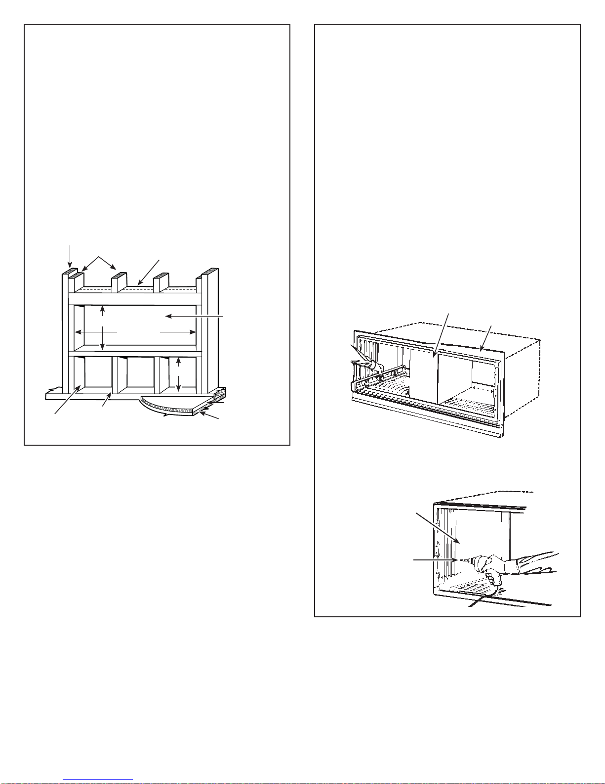
Étanchéisation
Étanchéisez les espaces entre les murs extérieur et
intérieur, et le boîtier avec du calfeutrement ou un matériau
d’étanchéisation équivalent.
REMARQUE :
*Il est crucial de calfeutrer le périmètre autour du
boîtier mural sur les quatre côtés, sur l’extérieur et
le côté pièce, à l’endroit où il rejoint le bâtiment pour
empêcher l’infiltration d’air et d’eau.
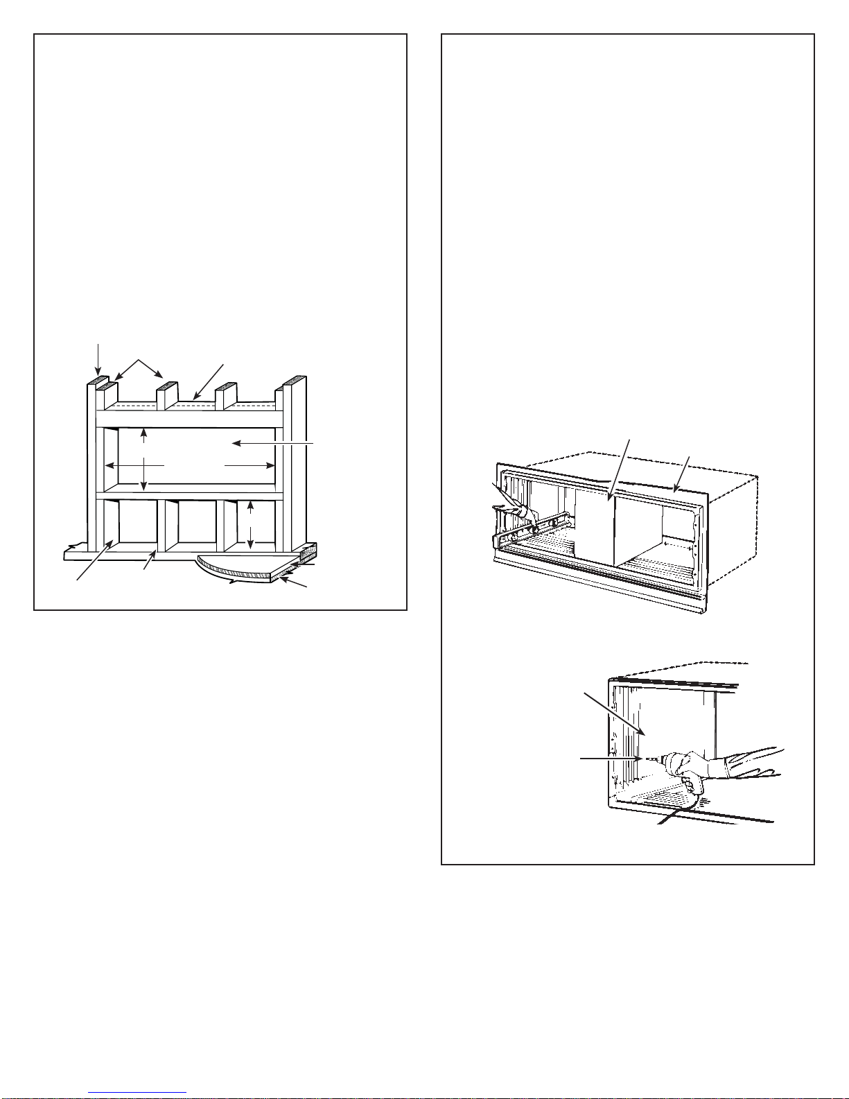
Pour une installation dans des murs très épais
1. Si le boîtier est installé dans un mur épais où le boîtier
HVWHQFDVWUpGHSOXVGHSRRQGRLWXWLOLVHUXQH
extension de boîtier avec des séparateurs alignés avec
les feuilles d’extrémité de condensateur de châssis.
2. Si le boîtier est installé dans un mur épais où le boîtier
HVWHQFDVWUpGHPRLQVGHSRHWTX¶RQXWLOLVHSDVGH
boîtier mural allongé, on doit installer un solin sous le
boîtier et il doit s’étendre de 2 po de chaque côté. Le
solin doit comprendre une gouttière, comme illustré
dans la figure ci-dessous.
Remarque:
*Il est crucial de calfeutrer autour du périmètre du
boîtier mural, sur les quatre côtés, à l’endroit où il
rejoint le bâtiment pour empêcher l’infiltration d’air et
d’eau.
3
Grille
extérieure
gouttière
Boîtier
Calfeutrer* Solin
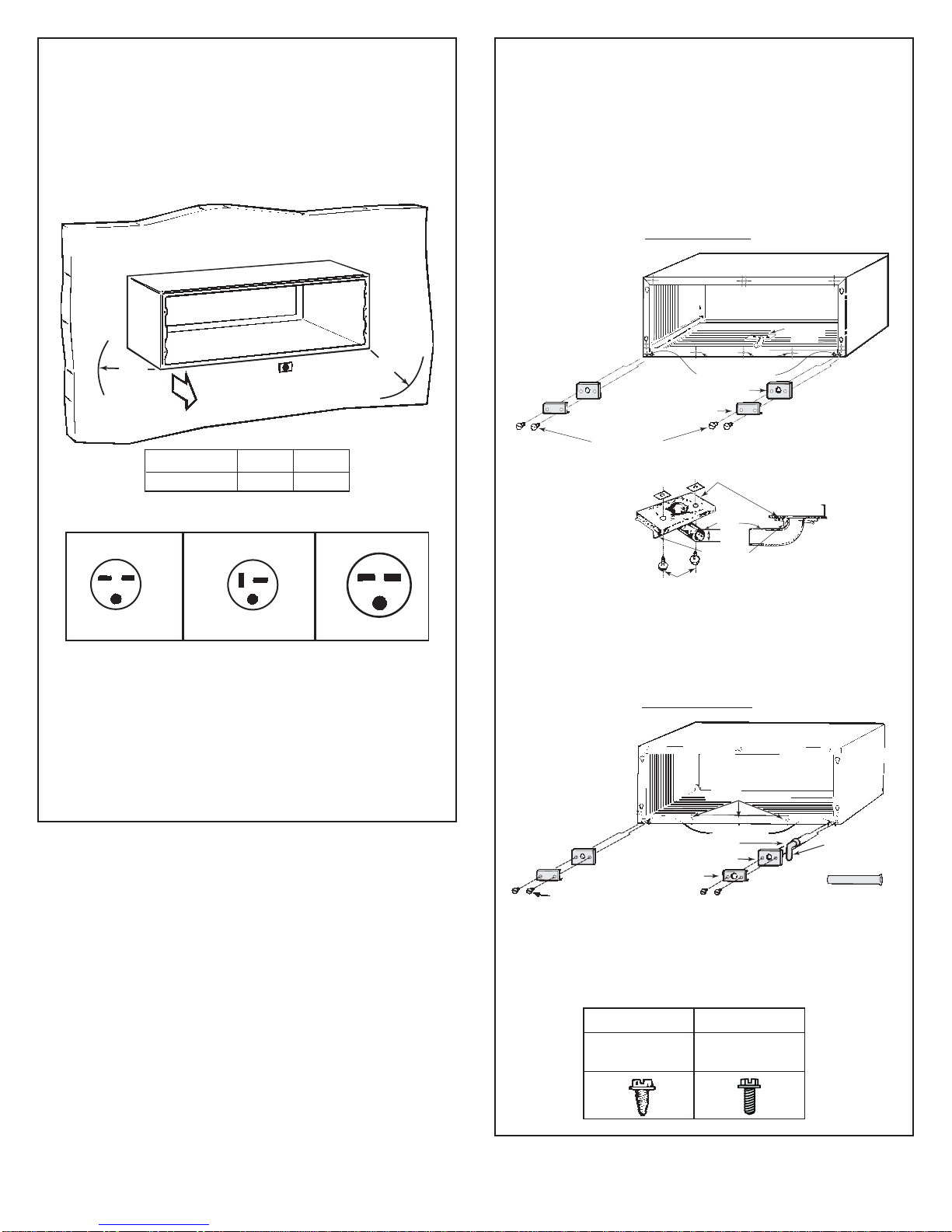
ÉTAPE 2 (suite)
Installation du boîtier dans l’ouverture
murale
3. Calfeutrez l’ouverture complète sur l’extérieur
entre le boîtier et l’extérieur du bâtiment
4. Calfeutrez l’ouverture en entier sur l’intérieur
entre le boîtier et l’intérieur du bâtiment.
REMARQUE:
Lors de l’utilisation d’un fixateur à cartouches,
un clou spécial (réf. pistolet à effet direct nº
6'JRXSLOOHPROHWpHjFDUWRXFKH
SRODUJ±SRGLDDYHFURQGHOOHHQDFLHU
SRGLDGRLWrWUHXWLOLVp1LpTXLSHPHQW
ni méthode ne doit être utilisé s’il n’est pas
conforme aux exigences de sécurité du
YROXPHGXUHJLVWUHIpGpUDOYROXPHQ
125 et à la norme nationale américaine pour
un système d’attache posée mécaniquement
$16,$/HQLYHDXGHSXLVVDQFH
de la charge de boîtier ne doit pas être
supérieur au niveau de puissance 1 identifié
par une charge de couleur grise.
Poteau nain
Montant principal
Vis à bois
Boulon à gaine
d’expansion ou à ailettes
Boulon
d’ancrage
d’expansion
Clou posé
mécaniquement
(consultez la remarque)
Aucun trou dans n’est permis dans la
base du boîtier (sauf pour l’ensemble
de drain interne RAD10)
Choix de dispositifs de fixation dans les
deux extrémités du boîtier ou le haut.
Aucun trou n’est permis dans la base
du boîtier
Grille
extérieure
Boîtier
Côté pièce
Steel lintel
Calfeutrer*
Solin
Gouttière
Calfeutrer*
Calfeutrer*
Finished
floor or top
of carpet
Calfeutrer*


 null")