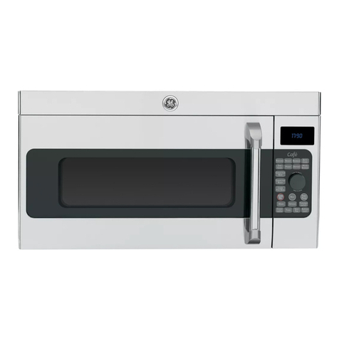
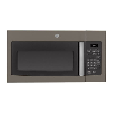
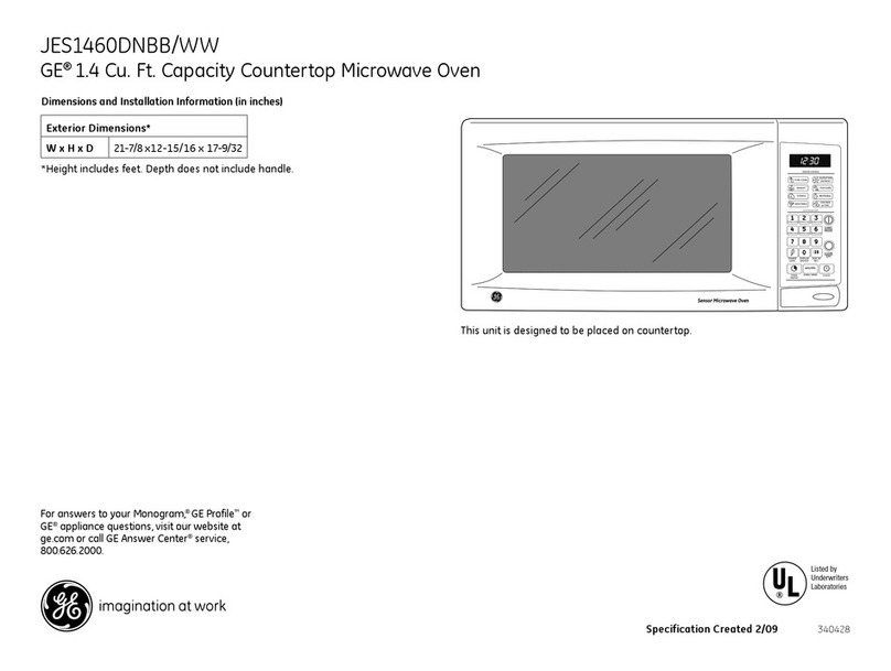
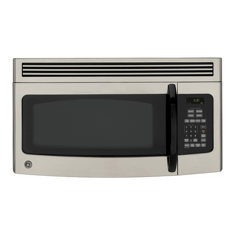
GE JVM1665 User manual

– 1 –
GE Appliances
General Electric Company
Louisville, Kentucky 40225
31-9184
GE Spacemaker®
Grilling
Over-the-Range
Microwave Oven
Technical Service Guide
June 2009
GE Consumer & Industrial
JVM1665
Auto
Grill Manual
Grill Combo
Grill
Combo
Grill
Combo
Grill
Combo
Grill
Combo
Grill
Power
Level
Add 30
Seconds
Options
Help
Tur n
Tab le
Timer Clock
Light
Vent
Start
Pause
Clear
Off
Soften
Melt
Defrost
Time
Cook

– 2 –
IMPORTANT SAFETY NOTICE
The information in this service guide is intended for use by individuals possessing
adequate backgrounds of electrical, electronic, and mechanical experience. Any attempt
to repair a major appliance may result in personal injury and property damage. The
manufacturer or seller cannot be responsible for the interpretation of this information,
nor can it assume any liability in connection with its use.
WARNING
To avoid personal injury, disconnect power before servicing this product. If electrical
power is required for diagnosis or test purposes, disconnect the power immediately after
performing the necessary checks.
RECONNECT ALL GROUNDING DEVICES
If grounding wires, screws, straps, clips, nuts, or washers used to complete a path to
ground are removed for service, they must be returned to their original position and
properly fastened.
GE Consumer & Industrial
Technical Service Guide
Copyright © 2009
All rights reserved. This service guide may not be reproduced in whole or in part
in any form without written permission from the General Electric Company.
PRECAUTIONS TO BE OBSERVED BEFORE AND DURING SERVICING TO AVOID POSSIBLE EXPOSURE
TO EXCESSIVE MICROWAVE ENERGY.
A. DO NOT OPERATE OR ALLOW THE OVEN TO BE OPERATED WITH THE DOOR OPEN.
B. IF THE OVEN OPERATES WITH THE DOOR OPEN, INSTRUCT THE USER NOT TO OPERATE THE OVEN
AND CONTACT THE MANUFACTURER IMMEDIATELY.
C. MAKE THE FOLLOWING SAFETY CHECKS ON ALL OVENS TO BE SERVICED BEFORE ACTIVATING
THE MAGNETRON OR OTHER MICROWAVE SOURCE, AND MAKE REPAIRS AS NECESSARY:
1. INTERLOCK OPERATION.
2. PROPER DOOR CLOSING.
3. SEAL AND SEALING SURFACES (ARCING, WEAR AND OTHER DAMAGE).
4. DAMAGE TO OR LOOSENING OF HINGES AND LATCHES.
5. EVIDENCE OF DROPPING OR ABUSE.
D. BEFORE TURNING ON MICROWAVE POWER FOR ANY TEST OR INSPECTION WITHIN THE
MICROWAVE GENERATING COMPARTMENTS, CHECK THE MAGNETRON, WAVE GUIDE OR
TRANSMISSION LINE AND CAVITY FOR PROPER ALIGNMENT, INTEGRITY AND CONNECTIONS.
E. ANY DEFECTIVE OR MISADJUSTED COMPONENTS IN THE INTERLOCK MONITOR, DOOR SEAL AND
MICROWAVE GENERATION AND TRANSMISSION SYSTEMS SHALL BE REPAIRED, REPLACED OR
ADJUSTED BY PROCEDURE DESCRIBED IN THIS MANUAL BEFORE THE OVEN IS RELEASED TO THE
OWNER.
F. A MICROWAVE LEAKAGE CHECK TO VERIFY COMPLIANCE WITH THE FEDERAL PERFORMANCE
STANDARD SHOULD BE PERFORMED ON EACH OVEN PRIOR TO RELEASE TO THE OWNER.

– 3 –
Table of Contents
12-Volt Light Transformer.............................................................................................................................................23
Bottom Thermal Cutout (TCO) .....................................................................................................................................17
Capacitor and Diode .......................................................................................................................................................22
Component Locator Views...........................................................................................................................................10
Components........................................................................................................................................................................14
Control Boards and Panel Connections .................................................................................................................13
Control Features...............................................................................................................................................................6
Control Operation Test ...................................................................................................................................................29
Control Panel Assembly.................................................................................................................................................16
Cooling Fan and Motor...................................................................................................................................................21
Diagnostics and Service Information......................................................................................................................27
Door Assembly...................................................................................................................................................................25
Door/Cavity Distance Test............................................................................................................................................29
Door Interlock Switches.................................................................................................................................................24
Griller Element....................................................................................................................................................................17
Heater Thermal Cutout (TCO) ......................................................................................................................................18
High Voltage Transformer............................................................................................................................................22
Hood Thermostat..............................................................................................................................................................18
Humidity Sensor................................................................................................................................................................20
Interior Light........................................................................................................................................................................15
Interlocks (Door Latch Switches)................................................................................................................................30
Introduction.........................................................................................................................................................................5
Key Panel Test....................................................................................................................................................................31
Line Fuse...............................................................................................................................................................................19
Magnetron............................................................................................................................................................................20
Magnetron Thermal Cutout (TCO)..............................................................................................................................18
Microwave Leak Test.......................................................................................................................................................29
Noise Filter ...........................................................................................................................................................................19
Nomenclature ....................................................................................................................................................................4
Outer Cover .........................................................................................................................................................................14
Oven Removal ....................................................................................................................................................................14
Oven Thermal Cutout (TCO)..........................................................................................................................................18
Performance Test .............................................................................................................................................................29
Schematics and Wiring Diagrams............................................................................................................................32
Smart Board........................................................................................................................................................................16
Stirrer Assembly ................................................................................................................................................................19
Surface Lamp Assemblies ............................................................................................................................................26
Surface Lamps...................................................................................................................................................................26
Turntable Motor.................................................................................................................................................................25
Vent Blower .........................................................................................................................................................................15
Vent Fan Motor Capacitor.............................................................................................................................................21
Warranty ..............................................................................................................................................................................34
– 4 –
Feature Pack
Designates Features - the higher
the number, the more features.
J V M 1 6 6 5 D 1 N B B
Installation
M = Microwave
Product Color
BB = Black
WW = White
SS = Stainless Steel
Model Year Designator
Model Number
The nomenclature plate is located inside the
microwave on the left side.
The mini-manual is located behind the
control panel on the right side of the oven.
Nomenclature
Microwave Oven
V = Over-the-Range Model
Product
J = GE Cooking Product
Cavity Size (cu. ft.)
16 = 1.6 cu. ft.
Nomenclature
Serial Number
The first two numbers of the serial number
identify the month and year of manufacture.
Example: AS123456S = January, 2009
A- JAN 2009 - S
D - FEB 2008 - R
F - MAR 2007 - M
G - APR 2006 - L
H - MAY 2005 - H
L - JUN 2004 - G
M - JUL 2003 - F
R - AUG 2002 - D
S - SEP 2001 - A
T - OCT 2000 - Z
V - NOV 1999 - V
Z - DEC 1998 - T

– 5 –
Introduction
The new Griller Microwave Oven is a versatile appliance for any kitchen. The Easy-Set Control Dial menu
system automatically leads you through each step of the cooking process.
Features and Benefits:
Grilling - The oven features 1,200-watt grilling power that generates radiant heat to brown the exterior of
food.
Auto Grill/Manual Grill - The oven offers the option of using automatic or manual grilling. Automatic grilling
allows you to select the correct food type from a pre-programmed menu. Manual grilling allows you to
specify the amount of time you wish to grill.
Sensor Cook - Microwave oven automatically adjusts the cooking time to various types and amounts of
food.
Easy-Set Control Dial - You can make selections on the oven by turning the dial and pressing it.
Control Lock-Out - Locks the control panel to prevent the oven from being accidently started.

– 6 –
Control Features
(Continued Next Page)
Microwave Cooking Time and Auto Features
Press Turn and push dial to enter
Time Cook Amount of cooking time
Press once to microwave any time
between 15 seconds and 95 minutes.
Add 30 Seconds Starts immediately!
Defrost
Press once (Fast) Food weight up to one pound
Press twice (Auto) Food weight up to six pounds
Press three times (Time) Amount of defrosting time
Beverage (6–12 oz.) Starts immediately!
Power Level Power level 1–10
Sensor Features
Press Turn and push dial to enter Option
Popcorn Starts immediately! more/less time
Potato Starts immediately! more/less time
Soften/Melt
Press once (soften) Food type
Press twice (melt) Food type
Auto Cook Food type more/less time
Grilling Features
Press Turn and push dial to enter
Auto Grill Food type/Specific food
Manual Grill Desired cook time
Combo Grill Food type/Specific food
Cooking Controls
Dial Selector

– 7 –
Microwave Cooking
The oven uses microwave energy to cook by a set time or weight, or
automatically by sensor.
Sensor microwave works by detecting the increasing humidity released
during cooking. The oven automatically adjusts the cooking time to
various types and amounts of food.
Available Cooking Options
_________________________________________________________________________________________
_________________________________________________________________________________________
Combination Grill
The oven also offers the option of using Combination Grill. This feature
allows for faster grilling by combining grilling and microwave energy.
(Continued next page)
Cooking Method
Microwave
energy is
distributed evenly
throughout
the oven for
thorough, fast
cooking of food.
Benefits
Fast, high
efficiency
cooking. Oven
and surroundings
do not get hot.
Easy clean-up.
Heat Conduction
Heat produced
within food by
instant energy
penetration.
Heat Source
Microwave
energy.
Auto Grill/Manual Grill
During grilling, a heating element is used to generate radiant heat
to brown the exterior of the food. The oven offers the option of using
automatic or manual grilling. Automatic grilling allows you to select the
correct food type from a pre-programmed menu. Manual grilling allows
you to specify the amount of time you wish to grill.
Cooking Method
Hot air radiates
around food
to produce a
browned exterior.
Benefits
Aids in
browning and
enhances flavor.
Heat Conduction
Heat conducted
from outside of
food to inside.
Heat Source
Radiating
heated air.
Cooking Method
Microwave
energy and
radiating heated
air combine to
grill foods faster.
Benefits
Shortened
grilling time
from microwave
energy, plus
browning
and flavor
enhancement.
Heat Conduction
Food heats
from instant
microwave
energy
penetration
and from heat
conducted from
outside.
Heat Source
Microwave
energy and
radiating
heated air.
For best results, use the grilling
shelf when using Combo
Grill unless the item you are
cooking is too large.
Always use the grilling shelf
when using Auto Grill or
Manual Grill unless the item
you are cooking is too large.

– 8 –
Auto Grill
Place grill tray and rack on the turntable. Place the food on the tray1.
and close the door.
Press the2. AUTO GRILL button.
Turn and press the dial to select the FOOD TYPE (Beef/Pork/Poultry/3.
Seafood).
When the FOOD TYPE has been selected, turn the dial to select the4.
specific food.
When the food selection has been entered, USE GRILL TRAY AND5.
RACK will be displayed to remind you that you must use these when
cooking with Auto Grill.
Press the6. START/PAUSE button and the grill time will be displayed.
If the food must be turned during cooking, a signal will sound once7.
and TURN FOOD will be displayed until the dial or button is pressed, or
the door is opened. When the door is open, PAUSE and the remaining
grill time will be displayed.
Press the dial or the8. START/PAUSE button. Cooking will resume and
the time countdown will be displayed.
Note: You may change the cook time at any time during cooking by
turning the dial.
_________________________________________________________________________________________
Manual Grill
Placing the grill tray and rack on the turntable is optional. Place food1.
on the tray and close the door.
Press the2. MANUAL GRILL button.
Turn and press the dial to enter the desired grill time.3.
Press the4. START/PAUSE.
If the door is opened, PAUSE and the remaining grill time will be5.
displayed.
Press the dial or the6. START/PAUSE button. Cooking will resume and
the time countdown will be displayed.
(Continued next page)

– 9 –
Combo Grill
Placing the grill tray and rack on the turntable is optional. Place food1.
on the tray and close the door.
Press the2. COMBO GRILL button.
Turn and press the dial to enter the FOOD TYPE and grill time.3.
The cooking combination COMBO 1 or COMBO 2 is automatically
determined by the food selection.
When the food type is selected, the preset time will be displayed. You4.
can rotate the dial to adjust the cooking time as desired.
Press the5. START/PAUSE button.
If the food must be turned during cooking, a signal will sound once6.
and TURN FOOD will be displayed until the dial or button is pressed, or
the door is opened. When the door is open, PAUSE and the remaining
grill time will be displayed.
Press the dial or the7. START/PAUSE button. Cooking will resume and
the time countdown will be displayed.

– 10 –
Component Locator Views
Front View
(Continued Next Page)
Front View - Control Panel Assembly Removed
Grill Assembly
Control Panel Assembly
Turntable Shaft
Bottom TCO
High Voltage Transformer
High Voltage Capacitor
Magnetron
Magnetron TCO
Fuse
Hood Thermostat
Noise Filter

– 11 –
Top View
(Continued Next Page)
Bottom View
Turntable Motor
Vent Blower
Heater TCO
12-Volt Light Transformer
Interior Light Assembly
Humidity Sensor
Cooling Fan
Oven TCO
Griller Element
Vent Fan Motor Capacitor

– 12 –
Right Side View
Left Side View
Vent Blower
Griller Element
Magnetron
High Voltage Transformer
Cooling Fan Motor
Cooling Fan
Fuse
Hood Thermostat

– 13 –
Smart Board
Control Boards and Panel Connections
CN1 - Oven Lamp, Fan Motor, Heater Relay (RY11),
Primary Interlock Switch (Top), Vent Motor, LVT
CN2 - Vent Motor, Cooktop Lamp, Turntable Motor
CN3 -Door Sensing Switch (Bottom), Hood
Thermostat
CN6 - Humidity Sensor
RY2 - Secondary Interlock Relay
RY11 - Heater Relay
(Front Side)
(Back Side)
RY11
CN1 CN2
CN3
CN6
RY11
RY2
Low Voltage Transformer

– 14 –
Components
Oven Removal
The oven is hooked on metal tabs at the bottom of
the wall mounting plate and fastened to the cabinet
with 3 top cabinet bolts.
To remove the oven from the cabinet or wall
opening:
WARNING: This oven requires 2 people for complete
oven removal.
Disconnect power to the oven.1.
For top-vented models, disconnect the duct and2.
remove the damper assembly.
Remove the 3 top cabinet bolts.3.
Caution: When removing the oven, be sure to
provide adequate support to prevent dropping the
unit.
Pull the unit forward slowly.4.
Outer Cover
To gain access to many of the oven components, it is
necessary to remove the outer cover.
To remove the outer cover:
Remove the oven. (See1. Oven Removal.)
Remove 1 Phillips-head screw from the bracket2.
that holds the power cord in place. Remove the
bracket.
3. Remove 8 Phillips-head screws from the top of
the oven.
CAUTION:
4. Remove 3 Phillips-head screws from the back of
the oven.
View From Rear
6. Slide the outer cover to the rear of the oven and
remove.
5. Remove 8 Phillips-head screws from the bottom
of the oven.
Bracket

– 15 –
Vent Blower
The three-speed vent blower can be directed
upward, to the rear, or re-circulated into kitchen
after installing the charcoal filter kit (part
numberWB02X10943).
The vent blower is located on the top rear of the
microwave oven. See installation instructions for
the proper method of directing the vent fan prior to
installing unit.
To remove the vent blower:
Remove the oven. (See1. Oven Removal.)
Remove 3 Phillips-head screws on the top of2.
the oven that hold the exhaust adapter in place,
then slide the exhaust adapter to the rear and
remove.
3. Remove the Phillips-head screw on the back of
the oven holding the vent blower in place.
4. Lift out the vent blower and place it on top of the
oven. Disconnect the electrical connector to the
vent blower.
Electrical Connector
View From Rear
View From Rear
Interior Light
The interior light bulb is 12 VAC, 20 watt (part
number WB36X10176).
To remove the interior light:
Remove 2 Phillips-head screws from the top of1.
the oven that attach the grill assembly to the
oven and remove the grill.
View From Rear
Disconnect
2. Remove the Phillips-head screw that attaches
the interior light assembly to the top of the
microwave oven.
(Continued next page)
Grill Assembly

– 16 –
3. Lift the light assembly up to expose the interior
light bulb.
4. Pull gently to remove the bulb.
Bulb
Control Panel Assembly
The control panel assembly consists of a smart
board, metal frame, touch pad/escutcheon, and a
knob. (4 parts)
To remove the control panel assembly:
Disconnect power to the microwave oven.1.
Remove 2 Phillips-head screws from the top of2.
the microwave that attach the grill assembly to
the oven and remove the vent.
3. Remove the Phillips-head screw that attaches
the control panel to the oven and pull the
control panel up and out to remove.
4. Mark and disconnect all the wiring harnesses to
the smart board.
Smart Board
To remove the smart board:
Remove the control panel assembly. (See1. Control
Panel Assembly.)
Pull the knob straight out and off of the control2.
board.
Knob
3. Disconnect the touch panel ribbon from the
smart board.
4. Remove 8 Phillips-head screws that attach the
smart board to the control board frame and lift
the smart board off the frame.
Disconnect
Grill Assembly

– 17 –
Bottom Thermal Cutout (TCO)
The bottom TCO is located on the bottom, right side
of the oven behind the control panel. The bottom
TCO is not resettable.
The bottom TCO has a temperature rating of 302°F.
To remove the bottom TCO:
Remove the control panel assembly. (See1. Control
Panel Assembly.)
Disconnect wiring to the bottom TCO.2.
Remove the Phillips-head screw attaching3.
the bottom TCO to the oven and pull the TCO
forward to remove.
Disconnect
Disconnect
Griller Element
The griller element is located on the top, left side of
the oven, inside the oven cavity. The griller element
operates on 120 VAC, is rated at 1200 watts, and
draws 10 amps.
To check continuity of heater element, place meter
leads:
L1 in at the fuse board (black wire).
Yellow wire to the heater relay on the control board.
Resistance should be approximately 11.5Ω.
Note: Door needs to be closed to perform check.
To remove the griller element:
Remove the outer cover. (See1. Outer Cover.)
Disconnect wiring to the griller element.2.
Tab
Tab
Tab
Tab
3. Using a small flat blade screwdriver, pry up the
four tabs that attach the griller element cover to
the oven.
Disconnect Disconnect
View From Left Side
4. Remove two 9/32-in. hex nuts from the griller
element.
View From Left Side
5. Open the oven door, and remove 2 Phillips-head
screws that attach the griller element to the top
of the oven and remove the element.

– 18 –
Hood Thermostat
The hood thermostat is a single pole thermostat
mounted on the base plate. The contacts close at
approximately 133°F. These contacts, when closed,
energize the vent fan.
To remove the hood thermostat:
Remove the control panel assembly. (See1. Control
Panel Assembly.)
Disconnect wiring to the hood thermostat.2.
Remove the Phillips-head screw attaching3.
the hood thermostat to the oven and pull the
thermostat forward to remove.
Disconnect
Disconnect
Oven Thermal Cutout (TCO)
The oven TCO is located on the top side of the oven
cavity beside the exhaust duct. The oven TCO is not
resettable.
The oven TCO has a temperature rating of 293°F.
To remove the oven TCO:
Remove the outer cover. (See1. Outer Cover.)
Disconnect wiring to the oven TCO.2.
Remove 2 Phillips-head screws attaching the3.
oven TCO to the oven and lift the TCO to remove.
Disconnect
Heater Thermal Cutout (TCO)
The heater TCO is located on the top side of the
oven cavity. The heater TCO is not resettable.
The heater TCO has a temperature rating of 302°F.
To remove the heater TCO:
Remove the outer cover. (See1. Outer Cover.)
Disconnect wiring to the heater TCO.2.
Remove 2 Phillips-head screws attaching the3.
heater TCO to the oven and lift the TCO to
remove.
Disconnect
Disconnect
Disconnect
Magnetron Thermal Cutout (TCO)
The magnetron TCO is located on the magnetron
and opens when the magnetron temperature
reaches 302°F.
The magnetron TCO is a normally closed switch. An
open reading across the TCO indicates a failed TCO.
The magnetron TCO is not resettable.
To remove the magnetron TCO:
Remove the control panel assembly. (See1. Control
Panel Assembly.)
Disconnect the wiring to the magnetron TCO.2.
Remove the Phillips-head screw and the3.
magnetron TCO from the magnetron.
Disconnect
Disconnect

– 19 –
Stirrer Assembly
The stirrer assembly consists of a blade, pin, and
cover. The blade is air driven and rotates on a shaft
embedded in the stirrer cover. The stirrer assembly
is located at the top of the oven cavity.
To remove the stirrer:
Disconnect power to the microwave oven and1.
open the door.
Remove 2 Phillips-head screws from the stirrer2.
cover.
Rotate the stirrer cover forward and remove the3.
stirrer cover.
Line Fuse
Note: When the 20-amp fuse is blown due to
operation of the monitor switch, the monitor switch
must be replaced. Also replace the relays and/or the
interlock switches when the continuity check shows
the contacts are shorted.
The unit is equipped with a 20-amp fuse (part
number WB27X10928).
The fuse is located in a receptacle near the top of
the noise filter and is common to all functions and
door switches.
To remove the fuse:
Remove the control panel assembly. (See1. Control
Panel Assembly.)
Remove the fuse.2.
Noise Filter
The noise filter helps to suppress electromagnetic
interference (EMI) radiating from the operation of
the oven and also protects the oven from any line
noise. The noise filter is located on the right side of
the oven behind the control panel. The noise filter is
held in place by two Phillips-head screws. The filter
assembly board can be accessed by removing the
control panel. The outer cover does not need to be
removed.
Note: When installing the noise filter, ensure all filter
wiring is connected to the correct terminals.
Check to make sure the fuse is not open. Check the
noise filter for approximate resistance value at the
following locations:
White (neutral input) to white (neutral output) - 0 Ω.
Black (line input) to black (line output) - 0 Ω.
White (neutral input) to black (line input) - 23 Ω.
Screw
Screw
Noise Filter
Fuse

– 20 –
Magnetron
WARNING: Prior to servicing the magnetron, be
certain the capacitor is discharged. Manually
discharge by placing an insulated-handle
screwdriver between the diode connection of the
capacitor and the oven chassis ground.
To check continuity of cooling fan, place meter
leads:
L1 in at the fuse board (black wire).
Pink wire to pin #7 of CN1 on the control board.
Resistance should be approximately 43Ω.
Note: Door needs to be closed to perform check.
To remove the magnetron:
Remove the control panel assembly. (See1. Control
Panel Assembly.)
Disconnect wiring to the magnetron.2.
Using a 1/4-in. drive socket wrench, short3.
extension, 1/4-in. socket, and a #2 Phillips bit,
remove the 3 Phillips-head screws that attach
the magnetron to the oven.
Humidity Sensor
The humidity sensor detects humidity changes
during sensor cook functions and transmits this
information to the smart board.
To remove the humidity sensor:
Remove the outer cover. (See1. Outer Cover.)
Disconnect the humidity sensor wire connector2.
from the control board. (See Control Boards and
Panel Connectors.)
Remove the Phillips-head screw attaching the3.
humidity sensor to the duct assembly.
Remove the Phillips-head screw that attaches4.
the ground wire to the microwave and lift the
humidity sensor to remove.
View From Right Side
Disconnect
Disconnect
(Continued next page)
Other manuals for JVM1665
6
Table of contents
Other GE Microwave Oven manuals

GE
GE Profile SpacemakerXL JVM1350SY User guide

GE
GE PEB2060SMSS - Countertop Microwave Oven Manual

GE
GE Spacemaker 164D2966P142 User manual

GE
GE Spacemaker D2092P129 User manual

GE
GE JEM31BF - Spacemaker II Microwave Oven User manual

GE
GE JEM25 Use and care manual

GE
GE JE1223L How to use

GE
GE JES0736SPSS User manual

GE
GE KOG-1MOT User manual

GE
GE JVM1630 Owner's User manual