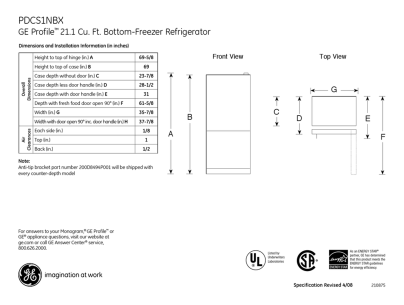
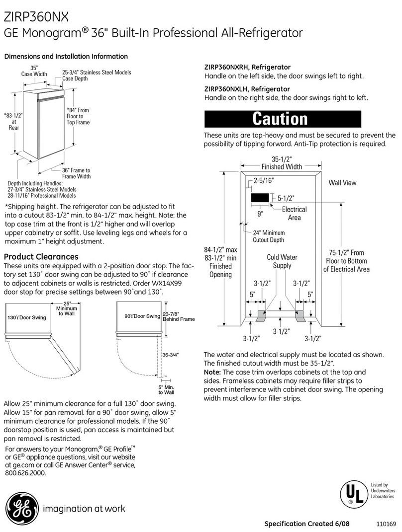
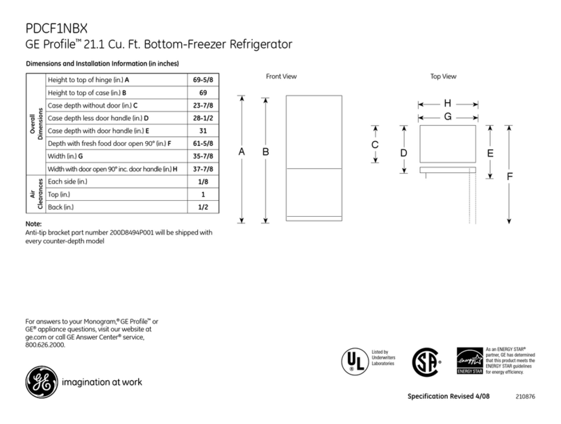
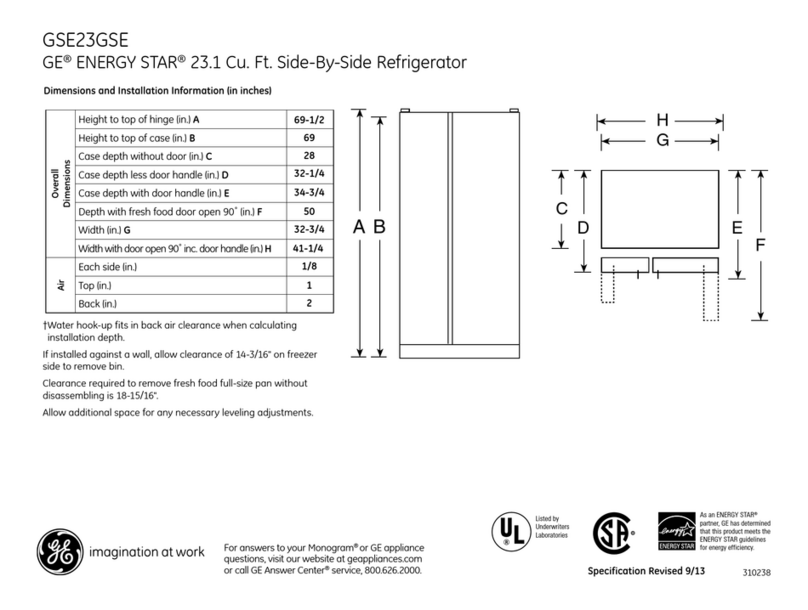
GE Side by Side Refrigerators User manual

Side by Side Refrigerators
Design Guide
With Installation Instructions
Installation
Instructions
09-13 GE
monogram.com
31-46514-2
224D1889P014

Safety Information
Skill Level – Installation of this refrigerator requires
basic mechanical, carpentry and plumbing skills.
Proper installation is the responsibility of the installer.
Product failure due to improper installation is not
covered under the GE Appliance Warranty.
See the Owner’s Manual for warranty information.
WARNING:
7KHVHUHIULJHUDWRUVDUHWRSKHDY\DQGPXVWEH
secured to prevent the possibility of tipping forward.
$QWL7LSSURWHFWLRQLVUHTXLUHG6HHSDJHIRU
details.
8VHWKLVDSSOLDQFHRQO\IRULWVLQWHQGHGSXUSRVH
,PPHGLDWHO\UHSDLURUUHSODFHHOHFWULFVHUYLFHFRUGV
that become frayed or damaged.
8QSOXJWKHUHIULJHUDWRUEHIRUHFOHDQLQJRUPDNLQJ
repairs.
5HSDLUVVKRXOGEHPDGHE\DTXDOLILHGVHUYLFH
technician.
AVERTISSEMENT
&HVUpIULJpUDWHXUVVRQWORXUGVHQKDXWHWLOIDXWOHV
DUULPHUSRXUpYLWHUOHXUEDVFXOHPHQW,OIDXWDYRLU
un système de protection contre le renversement.
9RLUOHVGpWDLOVSDJH
,OQHIDXWXWLOLVHUFHWDSSDUHLOTXHSRXUO·XWLOLVDWLRQ
DSSURSULpH
5pSDUHURXUHPSODFHULPPpGLDWHPHQWWRXWFRUGRQ
pOHFWULTXHHIILORFKpRXHQGRPPDJp
,OIDXWGpEUDQFKHUOHUpIULJpUDWHXUDYDQWOHQHWWR\DJH
ou toute intervention.
/HVUpSDUDWLRQVGRLYHQWrWUHIDLWHVSDUXQWHFKQLFLHQ
TXDOLILp
For Monogram local service in your area,
call 1.800.444.1845.
For Monogram service in Canada,
call 1.800.561.3344
For Monogram Parts and Accessories,
call 1.800.626.2002.
www.monogram.com
2
BEFORE YOU BEGIN
5HDGWKHVHLQVWUXFWLRQVFRPSOHWHO\DQGFDUHIXOO\
IMPORTANT – Save these instructions for
local inspector’s use. Observe all governing codes and
ordinances.
Note to Installer – Be sure to leave these
LQVWUXFWLRQVZLWKWKH&RQVXPHU
Note to Consumer – Keep these instructions with
your Owner’s Manual for future reference.
WARNING:
7KLVDSSOLDQFHPXVWEHSURSHUO\JURXQGHG6HH
´*URXQGLQJWKH5HIULJHUDWRUµSDJH
AVERTISSEMENT
&HWDSSDUHLOGRLWrWUHFRUUHFWHPHQWPLVjODWHUUH
&RQVXOWH]© 0LVHjODWHUUHGXUpIULJpUDWHXU ªSDJH
If you received a damaged refrigerator, you should
immediately contact your dealer or builder.
CAUTION:
'XHWRWKHZHLJKWDQGVL]HRIWKLVUHIULJHUDWRU
and to reduce the risk of personal injury or damage
WRWKHSURGXFW²7+5((3(23/($5(5(48,5('
)253523(5,167$//$7,212)$µ:,'(81,7
)2853(23/($5(5(48,5(')25,167$//$7,21
2)$µ25µ:,'(02'(/
PRUDENCE
FDXVHGXSRLGVHWGHODWDLOOHGHFHUpIULJpUDWRU
HWSRXUUpGXLUHOHULVTXHGHEOHVVXUHHWGHGRPPDJHV
,/)$87752,63(56211(63285,167$//(5
&255(&7(0(17'·81$33$5(,/'(FPSR
'(/$5*(,/)$8748$75(3(56211(63285
/·,167$//$7,21'·8102'Ê/('(28FP
28SR'(/$5*(
CONTENTS
Planning Guide
7KH,QVWDOODWLRQ6SDFH....................................... 3
'LPHQVLRQVDQG&OHDUDQFHV ..........................3
130° Door Swing..................................................4
90° Door Swing..................................................... 5
&XVWRPL]DWLRQ%DVLFV ........................................6
µ)UDPHG3DQHO'LPHQVLRQV....................
µ2YHUOD\3DQHO'LPHQVLRQV ....................8
5DLVHG2YHUOD\3DQHO'HVLJQ.........................9
Side Panels .......................................................... 10
Installation Instructions
7RROV+DUGZDUH0DWHULDOV......................... 10
*URXQGLQJWKH5HIULJHUDWRU........................ 10
6WHS5HPRYH3DFNDJLQJ......................... 11
6WHS0RYH5HIULJHUDWRULQWR+RXVH... 11
6WHS,QVWDOO:DWHU/LQH...................... 11-12
6WHS+RXVHKROG:DWHU)LOWUDWLRQ ........ 12
Step 5, Install Side Panels ........................... 12
6WHS,QVWDOO$QWL7LS%UDFNHWV................ 12
6WHS/HYHO5HIULJHUDWRU............................ 13
6WHS$OWHUQDWH$QWL7LS3URFHGXUH ..... 13
Step 9, 6HFXUH5HIULJHUDWRUWR&DELQHWU\ .14
Step 10, Adjust Door Swing ........................ 14
Step 11, Install Grille Panel ......................... 14
Step 12, Install Framed Panels ................. 15
Step 12A, Install Overlay Panels ........²
6WHS,QVWDOO'LVSHQVHU7ULP................... 18
6WHS&RQQHFW:DWHU6XSSO\ ............... 18
6WHS&RQQHFW3RZHU .............................. 19
Step 16, Start Icemaker ................................ 19
6WHS,QVWDOO7RHNLFN ................................. 19
ZKHSS2 Tubular Handle Kit
6WHS5HPRYH'RRU+DQGOHV.................. 20
6WHS,QVWDOO+DQGOHVRQWR3DQHOV........ 21
6WHS,QVWDOO$VVHPEOHG+DQGOHV.......... 22
6WHS,QVWDOO'LVSHQVHU7ULP.................... 22

B
A
Design Guide
THE INSTALLATION SPACE
Water And Electrical Locations
7KHRSHQLQJPXVWEHSUHSDUHGZLWKWKHHOHFWULFDO
and the cold water supply located as shown.
The cutout depth must be 24”
7KHUHIULJHUDWRUZLOOSURMHFWIRUZDUGVOLJKWO\EH\RQG
adjacent cabinetry, depending on your installation.
Cutout depth beneath a soffit:
When installed beneath a soffit, the soffit cannot
H[FHHGWKHµLQVWDOODWLRQGHSWKVKRZQ7KHWRSFDVH
trim overlaps the bottom of the soffit.
Additional Specifications
$YROW+]RUDPSSRZHUVXSSO\LV
required. An individual properly grounded branch
circuit or circuit breaker is recommended. Install
a properly grounded 3-prong electrical receptacle
recessed into the back wall. Electrical must be
located on the rear wall as shown.
NOTE:*),JURXQGIDXOWLQWHUUXSWHULVQRW
recommended.
7KHZDWHUOLQHFDQHQWHUWKHRSHQLQJWKURXJK
WKHIORRURUEDFNZDOO7KHZDWHUOLQHVKRXOGEHµ
2'FRSSHUWXELQJRU*(6PDUW&RQQHFW™kit between
the cold water line and water connection location,
long enough to extend to the front of the refrigerator.
Installation of an easily accessible shut-off valve
in the water line is required.
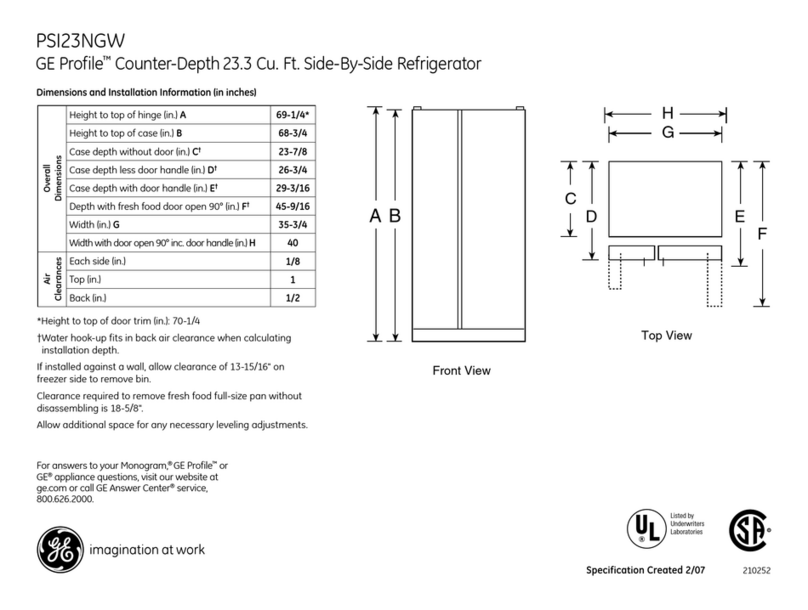
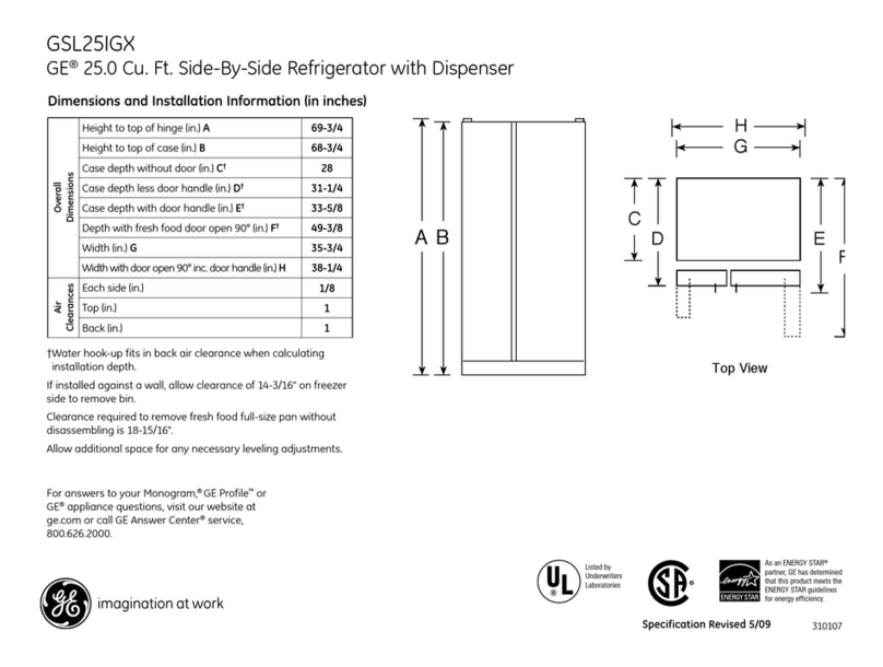
DIMENSIONS AND CLEARANCES
* Shipping height.
The refrigerator can
be adjusted to fit
into a cutout that
is 83-1/2” min. to
84-1/2” max. height.
Note that the top
case trim at the
front is 1/2” higher
and will overlap
upper cabinetry or
soffit. Use leveling
legs and wheels
for a maximum 1”
height adjustment.
Product Clearances
7KHVHUHIULJHUDWRUVDUHHTXLSSHGZLWKDSRVLWLRQGRRU
VWRS7KHIDFWRU\VHWGRRUVZLQJFDQEHDGMXVWHG
to 90° if clearance to adjacent cabinets or walls
is restricted.
3
*The finished cutout width must be:
35-1/2” for 36” models
41-1/2” for 42” models
47-1/2” for 48” models
90° Door Swing130° Door Swing
*Finished Width
6"
5"
Electrical
Area
84 1/2" max
83 1/2" min
Finished
Opening 75" From Floor
to Bottom
of Electrical
Area
24"
5" 5" 3 1/2"
Water Supply
3 1/2"
36" Models 12"
42" Models 18"
48" Models 20"
$OORZPLQLPXPFOHDUDQFHVIRUWKHIUHH]HUGRRU
'LPHQVLRQ$DQGIUHVKIRRGGRRU'LPHQVLRQ%
for a full 130° door swing and to allow for pan removal.
)RUDGRRUVZLQJDOORZµPLQFOHDUDQFHWRDZDOO
IRUIUDPHGDQGVWDLQOHVVVWHHOPRGHOV$OORZµPLQ
clearance for professional series models. If the 90° door
stop position is used, pan access is maintained, but pan
removal is restricted.
See the illustrations on pages 4 and 5 to determine door
swing interaction with adjacent cabinets or countertops.
Models A B C
36” 13” 15” 20-5/8”
42” 13” 19” 26-5/8”
48” 15” 20” 28-5/8”
*84" From
Floor to
Top Frame
25-3/8" Framed Models
25-3/4" Stainless Steel Models
Depth Including Handles:
26-7/8" Framed Models
27-3/4" Stainless Steel Models
28-11/16" Professional Models
36", 42" or 48"
Frame to Frame
35", 41", or 47"
Case Width
*83-1/2"
at
Rear
23-7/8"
Behind
Frame
C
90 Door Swing
*Min. Distance
to Wall
*4” Stainless and
Trimmed Models.
5” Pro Series

1/4" 1/2" 3/4" 1" 1-1/4"
1"
3/4" Overlay
Panel
(Nominal Size)
Stainless Steel
1/4"
1/2"
3/4"
2"
1-1/4"
1-1/2"
1-3/4"
3"
2-1/4"
2-1/2"
2-3/4"
1/4"
1/2"
3/4"
Door
23-7/8" From
Rear of
Refrigerator
1"
Refrigerator
Case
Trim
Design Guide
Top View
130° DOOR SWING
(factory setting)
Scale 1:1
IMPORTANT NOTE –
FOR DISPENSER MODELS:
Dispenser models are supplied with two
dispenser trims, one to fit framed panels
and one for overlay panels. Dispenser trim
fit to the custom panel depends on correct
panel thickness. Framed panels must be
µQRPLQDO2YHUOD\SDQHOVVKRXOGEH
constructed as shown to accomplish a total
µWKLFNQHVV6HHSDJHVDQGIRUGHWDLOV
4
Frameless Cabinets: 7KHFDVHWULPRYHUODSV
FDELQHWVDWWKHWRSDQGVLGHV7KHUHIRUH
frameless cabinets may require filler strips
to prevent interfeence with cabinet door
VZLQJ7KHRSHQLQJPXVWDOORZIRUILOOHUVWULSV

1/4"
1/2"
3/4"
1"
1-1/4"
1/4"
1/2"
3/4"
1"
1-1/4"
1-1/2"
23-7/8"
From Rear of
Refrigerator
3/4" Overlay
Panel
(Nominal Size)
Case Trim
Refrigerator
Door
Stainless Steel
5
Top View
90° DOOR SWING
(optional setting)
Scale 1:1
IMPORTANT NOTE –
FOR DISPENSER MODELS:
Dispenser models are supplied
with two dispenser trims, one to fit
framed panels and one for overlay
panels. Dispenser trim fit to the
custom panel depends on correct
panel thickness. Framed panels
PXVWEHµQRPLQDO2YHUOD\
panels should be constructed as
VKRZQWRDFFRPSOLVKDWRWDOµ
WKLFNQHVV6HHSDJHVDQGIRU
details.
Frameless Cabinets:
7KHFDVHWULPRYHUODSV
cabinets at the top
DQGVLGHV7KHUHIRUH
frameless cabinets may
require filler strips to
prevent interference
with cabinet door swing.
7KHRSHQLQJPXVWDOORZ
for filler strips.
Design Guide

Standard Door Handles
3/4" OverlayPanel
.10" Thick Spacer Panel
1/4" Thick Backer Panel
CUSTOMIZATION BASICS:
Framed Or Overlay Panels, Custom Handles and Accessory Kits
Overlay panels
You may also choose to install custom overlay panels from
\RXUFDELQHWPDQXIDFWXUHU7KLVGHVLJQSURYLGHV
a seamless appearance which integrates smoothly with
surrounding cabinetry.
Standard supplied handles shown in 3/4” overlay panel position.
Professional Style Stainless Steel Refrigerators
Stainless steel wrapped refrigerators have beveled edges
DQGSURIHVVLRQDOVW\OHKDQGOHV7KHVHPRGHOVDUHVKLSSHG
ready for installation.
Stainless Steel Wrapped Refrigerators
Stainless Steel wrapped refrigerators have wrapped doors
and grille panel, beveled edges, and tubular stainless steel
handles that coordinate with other Monogram appliances.
7KHVHPRGHOVDUHVKLSSHGUHDG\IRULQVWDOODWLRQ
Trimmed Refrigerators
7ULPPHGUHIULJHUDWRUVDUHGHVLJQHGWREHFXVWRPL]HG
with decorative panels. Field installed custom door
and grille panels are required.
Framed panels
<RXPD\LQVWDOOµWKLFNFXVWRPSDQHOVIURP
\RXUFDELQHWPDQXIDFWXUHU7KHGHFRUDWLYHSDQHOVOLGHV
into the factory installed trim. Order black or stainless steel
accessory panels from your Monogram dealer.
6
Standard supplied handles shown in 1/4” panel position.
Door Handles
7KHVWDQGDUGVXSSOLHGKDQGOHVFDQEHDGMXVWHGWR
DFFRPPRGDWHERWKIUDPHGRURYHUOD\SDQHOV&XVWRP
handles of your choice, supplied by your cabinet maker
FDQDOVREHLQVWDOOHGRQµRYHUOD\SDQHOV,IGHVLUHG
\RXPD\RUGHU=.+660RQRJUDPVWDLQOHVVVWHHO
WXEXODUKDQGOHNLWIRUµRYHUOD\SDQHOV
Side Panels
Side panels must be used whenever the sides
of the refrigerator will be exposed.
Optional Accessory Kits
=.+660RQRJUDP7XEXODU6WDLQOHVV6WHHOKDQGOHV
GHVLJQHGWRILWµRYHUOD\SDQHOV
=.+3663URIHVVLRQDO7XEXODU6WDLQOHVV6WHHOKDQGOHV
GHVLJQHGWRILWµRYHUOD\SDQHOV.LWLQFOXGHVRQH
handle. Order 2 kits for side-by-side refrigerator models
from your Monogram supplier
Framed Panel
Standard Door Handles
Design Guide

1/4” FRAMED PANEL DIMENSIONS
If you choose to install framed panels, they must
EHFXWWRWKHGLPHQVLRQVVKRZQ7KHSDQHOVZLOOVOLGH
into the frame on the door and grille.
Non-Dispenser Models
,IWKHFXVWRPSDQHOLVOHVVWKDQµWKLFNDQGLWILWV
loosely in the door frame it can be backed up with
a piece of filler material or foam tape to improve
the fit.
Fresh
Food
Panel
Freezer
Panel
E
D
F
G
A
B
Grille Panel
C
Dispenser
Cutout
9-5/8"
Dispenser Cutout
15-3/8
"
6LGHE\6LGHLQLQFKHV
$ % & ' ( ) *
µ0RGHOV
µ0RGHOV
µ0RGHOV
Dispenser
&XWRXW3RVLWLRQ
IMPORTANT NOTE: Maximum total panel weight:
Fresh food door panel – 75 lbs.
Freezer door panel – 53 lbs.
Grille Panel – 18 lbs.
1/4"
Panel
Door
5/16"
Trim
Reveal
The framed panel must be 1/4” nominal
thickness to fit the dispenser trim.
IMPORTANT NOTE – DISPENSER MODELS
7KHUHIULJHUDWRULVVXSSOLHGZLWKWZRGLVSHQVHUWULPV
one for framed panels and one for overlay panels.
,IWKHSDQHOLVOHVVWKDQµWKLFNDQRWLFHDEOHJDS
may be created around the dispenser trim. Foam
tape may be applied on the door to improve the fit.
,IWKHSDQHOLVPRUHWKDQµWKLFNWKHGLVSHQVHU
trim cannot be secured to the door.
See Dispenser Trim Fit Example, page 9.
Design Guide

3/4” OVERLAY PANEL DIMENSIONS
For a more custom appearance, overlay panels may
EHLQVWDOOHGRQWULPPHGPRGHOV7KHRYHUOD\SDQHOPXVW
EHVHFXUHGWRDµWKLFNEDFNHUSDQHOZKLFKVOLGHV
LQWRWKHWULP$VSDFHUSDQHOµWKLFNPXVWEHSODFHG
between the overlay and backer panel.
Assemble the panels with glue and screws:
&HQWHUWKHVSDFHUSDQHORQWKHEDFNHUSDQHOOHIWWR
right and top to bottom. Secure the panels with glue.
&HQWHUWKHVSDFHUDQGEDFNHUSDQHORQWKHRYHUOD\
panel and secure with glue and screws. Screws must
be countersunk into the backer panel.
NOTE: Left-to-right offset is
not always equal to top-to-
bottom offset.
8
Spacer Panel
OverlayPanel
Backer Panel
Fresh
Food
Panel
Freezer
Panel
E
D
F
G
A
B
Grille Panel
C
Dispenser
Cutout
9-5/8"
Dispenser Cutout
15-3/8
"
&XWWKHGLVSHQVHURSHQLQJDIWHUWKHEDFNHUVSDFHUDQGRYHUOD\
panels have been assembled.
µ6LGHE\6LGHLQLQFKHV
$ % & ' ( ) *
µ%DFNHU3DQHO
µ6SDFHU3DQHO
µ2YHUOD\3DQHO
µ6LGHE\6LGHLQLQFKHV
$ % & ' ( ) *
µ%DFNHU3DQHO
µ6SDFHU3DQHO
µ2YHUOD\3DQHO
µ6LGHE\6LGHLQLQFKHV
$ % & ' ( ) *
µ%DFNHU3DQHO
µ6SDFHU3DQHO
µ2YHUOD\3DQHO
*Dispenser
&XWRXW3RVLWLRQ
IMPORTANT NOTE: Maximum total weight for the assembled
SDQHOV
)UHVKIRRGGRRUSDQHO²OEV
)UHH]HUGRRUSDQHO²OEV
Grille Panel – 18 lbs.
IMPORTANT NOTE – DISPENSER MODELS
7KHUHIULJHUDWRULVVXSSOLHGZLWKWZRGLVSHQVHUWULPV
RQHIRUIUDPHGSDQHOVDQGRQHIRURYHUOD\SDQHOV7KH
overlay dispenser trim is designed to fit a total panel
WKLFNQHVVRIµ
,IWKHSDQHOLVOHVVWKDQµDQRWLFHDEOHJDSPD\
be created around the dispenser trim.
,IWKHSDQHOLVPRUHWKDQµWKHGLVSHQVHUWULP
cannot be secured to the door.
See Dispenser Trim Fit Example, page 9.
.250” + .10” + .750” = 1.100” Total Panel Thickness
7KHRYHUOD\SDQHOPXVWEHFRQVWUXFWHGDFFRUGLQJWR
the specifications shown to achieve the correct total
thickness.
$OWHUQDWLYHSDQHOFRQVWUXFWLRQPHWKRGVVXFKDV
VHFXULQJDµSDQHOWRDµEDFNHUSDQHOFDQQRW
EHXVHG$QRWKHUPHWKRGURXWLQJDµWKLFNSDQHO
RQDOOVLGHVFDQQRWEHXVHG7KHVHPHWKRGVZLOOQRW
UHVXOWLQWKHUHTXLUHGµSDQHOWKLFNQHVV
When a raised panel design is to be used, a custom
middle rail is required. See page 9 for details.
3/4"
Overlay
Panel
1/4"
Backer
Panel
Door
.10"
Spacer
Design Guide

DISPENSER MODELS:
RAISED OVERLAY PANEL DESIGN
When a raised panel design is to be used,
a custom wide middle rail is required to accept
the dispenser trim.
7KHPLGGOHUDLOPXVWEHZLGHHQRXJKWRDOORZ
for the dispenser trim to overlap the opening.
7KHPLGGOHUDLOPXVWEHµWRWDOWKLFNQHVV
to accept the dispenser trim.
9
DISPENSER TRIM FIT EXAMPLES:
(NOT TO SCALE)
1/4” FRAMED PANEL
7KHGLVSHQVHUWULPILWVRYHUWKHFXVWRP
SDQHODQGVQDSVLQWRWKHIUHH]HUGRRU
7KHFOLSVZLOOQRWHQJDJHWKHGRRU
LIWKHSDQHOLVPRUHWKDQµWKLFN
,IWKHSDQHOLVOHVVWKDQµWKLFN
a noticeable gap may be created
around the dispenser trim.
3/4” OVERLAY PANEL
7KHGLVSHQVHUWULPILWVRYHUWKHFXVWRP
SDQHODQGVQDSVLQWRWKHIUHH]HUGRRU
7KHFOLSVZLOOQRWHQJDJHWKHGRRU
LIWKHSDQHOLVPRUHWKDQµWKLFN
,IWKHSDQHOLVOHVVWKDQµWKLFN
a noticeable gap may be created
around the dispenser trim.
1
/
4" Backer Panel
.10" Spacer
3/4" OverlayPanel
Wide
Middle
Rail is
Required
Dispenser
Trim
16-3/4"
10-5/8"
Design Guide

GROUNDING THE REFRIGERATOR
IMPORTANT – (Please read carefully)
)253(5621$/6$)(7<7+,6$33/,$1&(0867
%(3523(5/<*5281'('
7KHSRZHUFRUGRIWKLVDSSOLDQFHLVHTXLSSHG
ZLWKDSURQJJURXQGLQJSOXJZKLFKPDWHV
ZLWKDVWDQGDUGSURQJJURXQGLQJZDOOUHFHSWDFOH
WRPLQLPL]HWKHSRVVLELOLW\RIHOHFWULFVKRFNKD]DUG
from this appliance.
+DYHWKHZDOORXWOHWDQGFLUFXLWFKHFNHGE\
a qualified electrician to make sure the outlet
is properly grounded.
Where a standard 2-prong wall outlet is encountered,
it is your personal responsibility and obligation
to have it replaced with a properly grounded
3-prong wall outlet.
'212781'(5
$1<&,5&8067$1&(6
&87255(029(
7+(7+,5'*5281'3521*
)5207+(32:(5&25'
'212786($1$'$37(53/8*72&211(&7
7+(5()5,*(5$72572$3521*287/(7
'212786($1(;7(16,21&25':,7+7+,6
$33/,$1&(
10
SIDE PANELS
Side panels must be used
whenever the sides of the
refrigerator will be exposed.
7KHµVLGHSDQHOVZLOO
slip into the side case trim.
Secure the panels to the
refrigerator with stick-on
hook and loop fastener
strips. Order the side
panels from the cabinet
manufacturer.
&XWDQRWFKLQWKHWRS
front corner as shown
to allow clearance for
corner keys in the front
side trim.
* Depending on installation height.
TOOLS AND MATERIALS REQUIRED
7LQVQLSVWRFXWEDQGLQJ
6WHSODGGHU
µ%LWH[WHQVLRQ
7DSHPHDVXUH
*ORYHV
µ'U\ZDOOVFUHZV
*DO%XFNHWZLWKFRYHU
µ6SLULWOHYHO
$SSOLDQFHKDQGWUXFN
7XELQJFXWWHU
µRSHQHQGZUHQFK
3KLOOLSVVFUHZGULYHU
'ULOODQGDSSURSULDWHELWV
µµVRFNHW
6DIHW\JODVVHV
µRSHQHQGZUHQFK
3OLHUV
µµ&RPER5DFKHW
µORQJ[IRU$QWL7LSVXSSRUW
µFRSSHUZDWHUOLQHWXELQJRU*(6PDUW&RQQHFW™
5HIULJHUDWRU7XELQJNLWV
:DWHUVKXWRIIYDOYH
&XVWRPSDQHOVIRUGRRUVDQGJULOOHSDQHO
6FUHZVWRVHFXUHUHIULJHUDWRUWRFDELQHWU\
6WLFNRQKRRNDQGORRSIDVWHQHUVWULSVIRU
µVLGHSDQHOV
FLOORING
For proper installation, this refrigerator must be placed
on a level surface of hard material that is at the same
KHLJKWDVWKHUHVWRIWKHIORRULQJ7KLVVXUIDFHVKRXOG
be strong enough to support a fully loaded refrigerator,
or approximately 1,500 lbs.
NOTE: 3URWHFWWKHILQLVKRIWKHIORRULQJ&XWDODUJH
section of the cardboard carton and place under
the refrigerator where you are working.
*84"
2-9/16"
24"
*3" to 4"
3/16"
1-7/8"
Design Guide
HARDWARE SUPPLIED
:DWHUILOWHUE\SDVVSOXJ
$QWL7LSEUDFNHWV
µQXWDQGIHUUXOH
'LVSHQVHUWULPVIRUµDQGµRYHUOD\SDQHOV
IRUXVHZLWK&XVWRP3DQHOPRGHOV
$OXPLQXPFRYHUWULPIRUµRYHUOD\SDQHOV
with custom handles. Includes 22 flat head screws
and 4 endcaps.

Installation Instructions
STEP 1 REMOVE PACKAGING
CAUTION7KHUHIULJHUDWRULVPXFKKHDYLHUDW
WKHWRSWKDQDWWKHERWWRP³EHFDUHIXOZKHQPRYLQJ
When using a hand truck, handle from the side only.
PRUDENCE/HUpIULJpUDWHXUHVWEHDXFRXS
SOXVORXUGHQKDXWTX·HQEDV,OIDXWrWUHSUXGHQWORUV
GHVGpSODFHPHQWV6LXQGLDEOHHVWXWLOLVpLOIDXWVRXOHYHU
OHUpIULJpUDWHXUVXUOHF{WpVHXOHPHQW
&DUHIXOO\FXWEDQGLQJDWWKHWRSDQGERWWRP
remove the outer carton.
6OLGHRXWWKHEDFNFRUQHUSRVWV
6OLGHWKHFDUWRQRIIWKHWRSRIWKHFDELQHW
NOTE: ,7,61271(&(66$5<72/$<7+(&$%,1(7'2:1
,125'(5725(029(7+(6.,'
7KHXQLWLVVHFXUHGWRWKHVNLGZLWKVORWWHG
WLHGRZQVWUDSV5HPRYHWKHVL[µEROWV
from the base channels in the tie-downs.
5HPRYHWKHVL[µ
bolts securing the straps
to the skid.
CAUTION'2127
$77(0377252//81,7
OFF SKID.
PRUDENCE,/1(
)$873$6(66$<(5'()$,5(
528/(5/(5e)5,*e5$7(85
3285/·(1/(9(5'(/$<
3$/(77(
STEP 3 INSTALL WATER LINE
$FROGZDWHUVXSSO\LVUHTXLUHGIRUDXWRPDWLF
LFHPDNHURSHUDWLRQ7KHZDWHUSUHVVXUHPXVW
be between 40 and 120 p.s.i.
5RXWHµ2'FRSSHURU*(6PDUW&RQQHFW™
plastic tubing between house cold water line
and the water connection location.
7KHWXELQJVKRXOGEHORQJHQRXJKWRH[WHQG
to the front of the refrigerator. Allow enough tubing
to accommodate the bend leading into the water line
connection.
11
Remov
e
Tie Dow
n
Toekick
7KHVXSSRUWEORFNVRQWKHERWWRPRIWKHUHIULJHUDWLRQ
case must be removed before the refrigerator is
WDNHQRIIWKHVNLGRUGDPDJHZLOORFFXU&DUHIXOO\
tilt the refrigerator and slide the blocks out from
beneath.
5HPRYHWKHWRHNLFNDQGVHWDVLGHIRUILQDOLQVWDOODWLRQ
/LIWWKHUHIULJHUDWRURIIWKHVNLGZLWKDQDSSOLDQFH
GROO\+DQGOHIURPWKHVLGHV
Floor
Cold Water Line
NOTE:7KHRQO\*(DSSURYHGSODVWLFWXELQJLVVXSSOLHG
LQWKH*(6PDUW&RQQHFW™5HIULJHUDWRU7XELQJNLWV
Do not use any other plastic water supply line because
the line is under pressure at all times. Other types
of plastic may crack or rupture with age and cause
water damage to your home.
*(6PDUW&RQQHFW™5HIULJHUDWRU7XELQJ.LWVDUH
DYDLODEOHLQWKHIROORZLQJOHQJWKV
·P:;;
·P:;;
·P:;;
·P:;;
STEP 2 MOVE THE REFRIGERATOR INTO THE HOUSE
5HXVHWKHFRUQHUSRVWVIURPWKHSDFNDJLQJWRSURWHFWVWDLQOHVVVWHHOPRGHOV5XQWKHDSSOLDQFHGROO\VWUDSVRYHU
the posts and under the handles.
/HDYHWKHSURWHFWLYHILOPRQWKHUHIULJHUDWRUXQWLOLQVWDOODWLRQLVFRPSOHWH
,03257$171HYHUOLIWWKHUHIULJHUDWRUE\WKHKDQGOHRUSXVKDJDLQVWWKHJULOOSDQHOWKLVFRXOGFDXVHGDPDJH
or misalignment.
$YRLGOD\LQJWKHXQLWRQLWVEDFNRUVLGHWRSUHYHQWVHDOHGV\VWHPUHVWULFWLRQV

12
STEP 4 INSTALLATION WITH
HOUSEHOLD WATER
FILTRATION SYSTEM
Skip this step if you do not have a household water
filtration system
If the water supply to the refrigerator is from
any household water filtration system, the filter
cartridge should be removed. For better ice and water
performance, remove the filter and install the filter bypass
plug.
STEP 5 INSTALL SIDE PANELS
Skip this step when not using side panels.
,I\RXDUHXVLQJµVLGHSDQHOVWKH\VKRXOG
be inserted into the case trim. Fasten the panels
to the refrigerator with stick-on hook and loop
fastener strips before setting the refrigerator in place.
STEP 6
INSTALL ANTI-TIP BRACKETS
:$51,1*:ANTI-TIP PRECAUTIONS
7KHUHIULJHUDWRULVWRSKHDY\DQGPXVWEHVHFXUHG
to prevent the possibility of tipping forward.
$77(17,21: PRECAUTIONS CONTRE
LES BASCULEMENTS
/HUpIULJpUDWHXUHVWEHDXFRXSSOXVORXUGHQKDXW
HWLOIDXWOHPDLQWHQLUHQSODFHSRXUpYLWHUODSRVVLELOLWp
de son basculement vers l’avant.
&XWDµ[µEORFNµORQJDQGVHFXUHWKHEORFN
WRWKHPRXQWLQJEUDFNHWVSURYLGHGXVLQJRU
wood screws.
6HFXUHWKHEUDFNHWZLWKZRRGEORFNWRWKHEDFNZDOO
VRWKDWLWLVµRU\RXULQVWDOODWLRQKHLJKWIURP
WKHILQLVKHGIORRU8VHRUZRRGVFUHZV
See the illustration.
7KHVFUHZVPXVWSHQHWUDWHDWOHDVWRQHLQFK
into the vertical wall studs.
Connect power cord:
%HIRUHSXVKLQJWKHUHIULJHUDWRULQWRWKHRSHQLQJSOXJ
the power cord into the receptacle. Open the grille
panel and reach into the opening at the back to grasp
the power cord. Pull the power cord into the opening
as you push the refrigerator back.
*HQWO\SXVKUHIULJHUDWRULQWRWKHRSHQLQJZLWKKDQGV
against front corners.
IMPORTANT NOTE: When the refrigerator is installed under a soffit
or if there is not enough height for this method of security, brackets
FDQQRWEHXVHG3URFHHGWRVWHSWROHYHOWKHUHIULJHUDWRUDQGWKHQWR
step 9 to secure refrigerator to cabinets. See step 8 if you have metal
ZDOOVWXGV7KHUHIULJHUDWRUPXVWEHVHFXUHGWRSUHYHQWWLSSLQJ
Installation Instructions
NOTE: &RPPRQZHDOWKRI0DVVDFKXVHWWV3OXPELQJ
&RGHV&05VKDOOEHDGKHUHGWR6DGGOHYDOYHV
are illegal and use is not permitted in Massachusetts.
&RQVXOWZLWK\RXUOLFHQVHGSOXPEHU
STEP 3 (continued)
Shut off the main water supply.
7XUQRQWKHQHDUHVWIDXFHWORQJHQRXJKWRFOHDUWKHOLQH
of water.
,QVWDOODVKXWRIIYDOYHEHWZHHQWKHLFHPDNHUZDWHU
valve and cold water pipe in a basement or cabinet.
7KHVKXWRIIYDOYHVKRXOGEHORFDWHGZKHUHLWZLOOEH
easily accessible.
7XUQRQWKHPDLQZDWHUVXSSO\DQGIOXVKGHEULV
5XQDERXWDTXDUWRIZDWHUWKURXJKWKHWXELQJLQWRD
bucket. Shut off the water supply at the shut-off valve.
127(6DGGOHW\SHVKXWRIIYDOYHVDUHLQFOXGHGLQPDQ\
water supply kits. Before purchasing, make sure a saddle
type valve complies with your local plumbing codes.
Filter Bypass
Plug
Rotate Counterclockwise To
Remove

13
STEP 7 LEVEL REFRIGERATOR
$OOPRGHOVKDYHSRLQWOHYHOLQJ7KHIURQWLV
supported by leveling legs, the rear is supported
by adjustable wheels. Both are accessible from
the front of the refrigerator.
7ROHYHOWKHEDFNRIWKHUHIULJHUDWRUWXUQWKHµ
KH[QXWORFDWHGDERYHWKHIURQWZKHHOV7XUQ
clockwise to raise or counterclockwise to lower the
refrigerator.
)RUIURQWOHYHOLQJXVHDµRSHQHQGZUHQFK
$GMXVWKHLJKWRIUHIULJHUDWRUWRPDWFKLQVWDOODWLRQ
FXWRXWRSHQLQJµWRµ7KHUHIULJHUDWRU
should be level and plumb with cabinetry.
STEP 8 ALTERNATE ANTI-TIP
PROCEDURE
The refrigerator must be secured to prevent tipping.
The anti-tip brackets cannot be used on metal
wall studs. Use this Alternate Procedure to secure
the refrigerator against tip-over whenever metal
wall studs are encountered and there is no soffit.
5DLVHWKHJULOOHSDQHOWRDFFHVVFDVHWULP
8VHDµELWWRGULOOIRXUHYHQO\VSDFHGFOHDUDQFH
holes through the metal top case trim.
8VHDµELWWRGULOOWRSLORWKROHVWKURXJKWKHPHWDO
FOHDUDQFHKROHVDQGLQWRWKHZRRGVRIILW7KHKROHV
VKRXOGEHFHQWHUHGLQWKHVRIILWRUDµPLQZRRG
EUDFH7KHEUDFHVSDQQLQJWKHHQFORVXUHPXVW
be securely fastened to cabinets on both sides.
,QVWDOOIRXUµGU\ZDOOVFUHZVLQWRWKHSLORWKROHV
CAUTION:
7KHUHDUOHYHOLQJZKHHOVDQGIURQWOHYHOLQJOHJV
DUHOLPLWHGWRDPD[LPXPKHLJKWDGMXVWPHQWRIµ
,IWKHLQVWDOODWLRQUHTXLUHVPRUHWKDQµKHLJKW
the installer should elevate the refrigerator on a sheet
RISO\ZRRGRUUXQQHUV&DELQHWU\WULPFRXOGDOVR
be added across the top of the opening to shorten
the opening. If you attempt to raise the refrigerator
more than 1”, you will damage the front leveling
legs and the rear leveling wheels. Make adjustments
in small increments.
PRUDENCE
/HVURXHVGHQLYHOOHPHQWDUULqUHHWOHVSDWWHVGH
QLYHOOHPHQWDYDQWSHUPHWWHQWXQUpJODJHPD[LPDO
GHPPSR6LO·RXYHUWXUHSRXUOHUpIULJpUDWHXU
DXQHKDXWHXUVXSpULHXUHjPSR
O·LQVWDOODWHXUGRLWpOHYHUOHUpIULJpUDWHXUVXUXQHIHXLOOH
GHFRQWUHSODTXpRXGHVJOLVVLqUHV,OHVWpJDOHPHQW
possible d’ajouter des baguettes de finition des
SODFDUGVVXUOHKDXWGHO·RXYHUWXUHDILQGHODUpGXLUH
Lever le réfrigérateur de plus de 25 mm (1 po)
endommage les pattes de nivellement avant
et les roues de nivellement arrière.
Installation Instructions

STEP 11 INSTALL GRILLE PANEL
(for Custom Panel Models only)
To insert the framed or overlay panel into the grille:
5DLVHWKHJULOOHSDQHOWRWKHVWRSSRVLWLRQ
14
/RRVHQWKHVFUHZVRQWKHVLGHWULPEHKLQGWKHIUDPH
5HPRYHWKHERWWRPWULP
CAUTION: 7KHPHWDOSDQHOPD\EH
slippery. Grip the metal panel firmly so the panel does
not slip out of the frame and cause personal injury or
damage to the frame.
PRUDENCE : /HSDQQHDXHQPpWDO
SHXWErWUHJOLVVDQW7HQLUIHUPHPHQWOHSDQQHDXHQ
PpWDOGHPDQLqUHjFHTXHOHSDQQHDXQHJOLVVHSDV
en dehors du cadre en provoquant des blessures
corporelles ou des dommages au cadre.
6OLGHWKHSDQHORYHUWKHPHWDOEDFNHUSDQHODQGLQWR
the trim.
,IQHFHVVDU\WDSZLWKDZRRGEORFNXQWLOWKHSDQHO
slips under the top trim piece.
5HDVVHPEOHWKHERWWRPWULP7LJKWHQWKHVFUHZV
$GMXVWWKHKLQJHVSULQJWRDFFRPPRGDWHWKHSDQHO
weight, if necessary.
Adjust Nut Below
Spring to Accommodate
Panel Weight
Loosen
Side
Trim
Screw
Loosen
Side
Trim
Screw
Installation Instructions
STEP 10 ADJUST DOOR SWING
127(7KLVUHIULJHUDWRUKDVDSRVLWLRQGRRUVWRS
When space does not allow the door to swing open
fully to 130°, you may change the door swing to a 90°
opening. Skip this step if door opening is satisfactory
for your installation situation.
2SHQWKHGRRUWRYLHZWKHERWWRPKLQJH
1RWHWKHGRRUVWRSSLQORFDWLRQV7KHSLQLVIDFWRU\
installed in the 130° position.
&ORVHWKHGRRU)URPEHORZXVHSOLHUVWRXQVFUHZ
the door stop and reinstall into the 90° position.
STEP 9 SECURE REFRIGERATOR
TO CABINETRY
Whenever possible, perform this step for anti-tip
security, or when anti-tip brackets cannot be used.
The refrigerator must be secured to prevent tipping.
5DLVHWKHJULOOHSDQHOWRDFFHVVWKHFDVHWULP
'ULOODKROHLQWKHWULPDQGGULYHDVFUHZWKURXJK
the trim into the adjacent cabinet.
)ROORZWKHVDPHSURFHGXUHRQWKHRSSRVLWHVLGH

15
STEP 12 INSTALL 1/4” FRAMED PANELS
Install door panels:
2SHQWKHGRRUWR5HPRYHWKH3KLOOLSVKHDGVFUHZV
from the door handle.
5HPRYHWKHKDQGOH5HWDLQDOOVFUHZV
5HPRYHWKHVFUHZVKROGLQJWKHWULPWKHQOLIWRII
WKHWULP5HWDLQWKHVFUHZV
6OLGHWKHIUDPHGSDQHOLQWRWKHGRRUWULP
Dispenser Models Only:
7KHGLVSHQVHUFRQWUROVSURWUXGHEH\RQGWKHIDFH
RIWKHIUHH]HUGRRU7RDYRLGGDPDJHWRWKHGLVSHQVHU
the trim at the top of the door should be removed.
5HPRYHWKHVFUHZVKROGLQJWKHWRSWULPLQSODFH
3ODFHWKHIUHH]HUSDQHOLQWRWKHERWWRPFKDQQHO
and slide into the hinge side trim.
5HLQVWDOOWKHWRSWULPSLHFHZLWKVFUHZV
7KHUHDUHWZRVHWVRIKROHVLQWKHKDQGOHVLGHWULP
5HSODFHWKHKDQGOHVLGHWULPE\LQVWDOOLQJWKHRULJLQDO
VFUHZVLQWKH)5217VFUHZKROHV
6HFXUHWKHKDQGOHWRWKHGRRUXVLQJWKH5($5VFUHZ
holes.
)ROORZWKHVDPHSURFHGXUHVWRLQVWDOOWKHRSSRVLWHSDQHO
&KHFNWREHVXUHWKHKDQGOHVDUHHYHQO\DOLJQHGZLWK
HDFKRWKHUDWWKHWRS7RDGMXVWORRVHQWKHKDQGOH
VFUHZVDQGVOLGHXSRUGRZQ7LJKWHQWKHVFUHZV
NOTE: Aluminum cover trim is supplied for use with
custom handles on overlay panels. It is not intended for
XVHZLWKµSDQHOV'LVFDUGWKHFRYHUWULPZKHQXVLQJ
µIUDPHGSDQHOV
Go to Step 12A for Overlay Panels
Supplied
Handle Shown
in 1/4” Panel
Position
Installation Instructions

16
STEP 12A INSTALL OVERLAY PANELS
Install door panels:
2SHQGRRUWR5HPRYHWKH3KLOOLSVKHDGVFUHZV
from the door handle.
5HPRYHWKHKDQGOH5HWDLQDOOVFUHZV
5HPRYHWKHVFUHZVKROGLQJWKHWULPWKHQOLIWRII
WKHWULP5HWDLQWKHVFUHZV
6OLGHWKHRYHUOD\SDQHOLQWRWKHGRRUWULP
Dispenser Models Only:
7KHGLVSHQVHUFRQWUROVSURWUXGHEH\RQGWKHIDFH
RIWKHIUHH]HUGRRU7RDYRLGGDPDJHWRWKHGLVSHQVHU
the trim at the top of the door should be removed.
5HPRYHWKHVFUHZVKROGLQJWKHWRSWULPLQSODFH
3ODFHWKHDVVHPEOHGIUHH]HUSDQHOLQWRWKHERWWRP
channel and slide into the hinge side trim.
5HLQVWDOOWKHWRSWULPSLHFHZLWKWKHVFUHZV
7KHUHDUHWZRVHWVRIKROHVLQWKHKDQGOHVLGHWULP
5HSODFHKDQGOHVLGHWULPE\LQVWDOOLQJWKHRULJLQDOVFUHZV
in the 5($5 screw holes.
6HFXUHWKHKDQGOHWRWKHGRRUXVLQJWKH)5217
screw holes.
)ROORZWKHVDPHSURFHGXUHVWRLQVWDOOWKHRSSRVLWHSDQHO
&KHFNWREHVXUHWKHKDQGOHVDUHHYHQO\DOLJQHGZLWK
HDFKRWKHUDWWKHWRS7RDGMXVWORRVHQWKHKDQGOH
VFUHZVDQGVOLGHXSRUGRZQ7LJKWHQWKHVFUHZV
Supplied Handle
Shown in Overlay
Panel Position
Installation Instructions

STEP 12A (continued)
Custom Handles
,I\RXDUHXVLQJFXVWRPKDQGOHVWKHKDQGOHPXVW
be properly secured to the overlay panel before sliding
the panel into the trim.
7KHFDELQHWPDQXIDFWXUHUZLOOVXSSO\WKHFXVWRP
handle and hardware.
'LVFDUGWKHVXSSOLHGKDQGOH
5HPRYHWKHWULP3HHODZD\DIHZLQFKHV
of the adhesive backing.
IMPORTANT: 7KHWDSHLVYHU\VWLFN\DQGVWURQJ2QFH
it adheres to a surface, it cannot be removed without
damaging both surfaces. Do not install the trim before
the final wood panels are in place. Be sure to align
the trim carefully before removing the paper backing.
Reinstall all original screws.
5HLQVWDOOWKHKDQGOHVLGHWULPXVLQJDOOVXSSOLHG
flat-head screws, plus the 12 flat-head screws
originally installed in the handle trim.
,QVWDOODVXSSOLHGHQGFDSRQWRWKHWRSRIWKHGRRU
using a Phillips head screwdriver and the 2 screws
provided. Hand-tighten the screws into the end caps.
Do not overtighten; damage will occur.
&OHDQWKHDOXPLQXPWULPZLWKUXEELQJDOFRKRO³
do not use alcohols with oil or lanolin that will prevent
adhesion of double-sided tape.
6OLSWKHDOXPLQXPFRYHUWULPEHKLQGWKHWRSHQGFDS
WRFKHFNWKHILW7KHDOXPLQXPFRYHUWULPKDVDUHFHVV
on each end which fits the end cap.
Installation Instructions
Top End Cap
Fits Over the
Aluminum Trim.
Secure Cap with
2 Screws.
End Cap
STEP 12A (continued)
&DUHIXOO\SODFHWKHDOXPLQXPFRYHUWULPLQWRWRS
end cap so that the recess is aligned with the cap.
8VHWKHWRSWRERWWRPJURRYHVDORQJWKHKDQGOHVLGH
to align the cover trim accurately. Pull the tape a few
inches at a time while pressing the trim against
the door. Press and hold approximately 10 seconds
before continuing along the length of the door.
,QVWDOODQRWKHUHQGFDSDWWKHERWWRPRIWKHGRRU
WRVHFXUHWKHFRYHUWULP8VHDVWXEE\3KLOOLSVKHDG
screwdriver and the 2 screws provided.
NOTE: Make sure there are no gaps in the installation.
)ROORZWKHVDPHSURFHGXUHRQWKHRSSRVLWHGRRU
Insert Aluminum
Trim Into End
Cap.
Cover Trim
End Cap

18
STEP 14 CONNECT WATER SUPPLY
/RFDWHDQGEULQJWKHWXELQJWRWKHIURQW
of the cabinet.
7XUQWKHZDWHURQWRIOXVKGHEULVIURPWKHOLQH
5XQDERXWDTXDUWRIZDWHUWKURXJKWKHWXELQJ
into a bucket, then shut off the water.
Copper Tubing:
6OLSDµQXWDQGIHUUXOHSURYLGHGRYHUERWKHQGVRI
the copper tubing. Insert the tube into the union fitting
on the unit and tighten the nut to the union.
7XUQRQWKHZDWHUWRFKHFNIRUOHDNV
GE SmartConnect™Tubing:
,QVHUWWKHPROGHGHQGRIWKHWXELQJ
LQWRWKHUHIULJHUDWRUFRQQHFWLRQ7LJKWHQ
the compression nut until it is just hand tight.
7LJKWHQRQHDGGLWLRQDOWXUQZLWKDZUHQFK
2YHUWLJKWHQLQJFDQFDXVHOHDNV
7XUQRQWKHZDWHUWRFKHFNIRUOHDNV
NOTE: Make sure excess tubing length does not
interfere with the toekick installation.
STEP 13 INSTALL DISPENSER TRIM
Skip this step is you are installing a stainless steel
wrapped or a non-dispenser refrigerator.
7KHUHDUHWZRGLVSHQVHUWULPVVKLSSHGZLWK\RXU
refrigerator. Select the appropriate trim for your
application.
3UHVVDQGVQDSWKHGLVSHQVHUWULPLQWRWKHGLVSHQVHU
recess on the refrigerator door.
If an excessive gap exists around the dispenser trim
or if the panel fits loosely in the door frame, foam tape
PD\EHDSSOLHGWRKHOSLPSURYHWKHILW5HPRYH
the trim and panel and apply the foam tape
to the door around the dispenser and in the corners.
&RPSDUHWKHGLVSHQVHUWULPV1RWHWKDW
the inside depth of the frames are different.
&KRRVHWKHWULPZLWKOHVVGHSWKIRUIUDPHG
panels, choose the deeper one for overlay
panels.
Dispenser trim fit over the custom panel depends on
FRUUHFWSDQHOWKLFNQHVV6HHSDJHVDQGIRUSDQHO
construction information.
Framed
Panel
Trim
Overlay
Panel
Trim
Refrigerator
Water Supply
House
Water Supply
Installation Instructions

19
STEP 17 INSTALL TOEKICKS
/RFDWHWKHVXSSOLHGWRHNLFNVVKLSSHGWDSHGWR
WKHVLGHRIWKHUHIULJHUDWRU
)LUVWDWWDFKWKH/$5*(5WRHNLFNWRWKHUHILJHUDWRU
XVLQJ21/<WKHWRSFHQWHUKROH
1H[WDWWDFKWKHWRHNLFNH[WHQVLRQWRWKHUHIULJHUDWRU
XVLQJWKHWKUHHORZHUVORWV
$FXVWRPWRHNLFNFDQEHLQVWDOOHGWRPDWFKRU
FRPSOHPHQWWKHVXUURXQGLQJFDELQHWU\8VHWKH
supplied toekick as a template to cut the shape.
STEP 16 START ICEMAKER
6OLGHWKHVZLWFKWR217KHLFHPDNHUZLOOEHJLQ
operation automatically.
%HVXUHQRWKLQJLQWHUIHUHVZLWKWKHVZHHS
of the feeler arm.
'LVFDUGWKHILUVWIXOOEXFNHWRILFHFXEHV
7RWXUQWKHLFHPDNHURIIVOLGHWKHVZLWFKWR2))
STEP 15 CONNECT POWER, CLOSE
GRILLE PANEL
2SHQWKHJULOOSDQHO
3OXJLQWKHSRZHUFRUGLIQHFHVVDU\E\UHDFKLQJ
into the opening next to the water filter. If access is
too tight, remove the 2 screws holding the water filter
bracket and move aside. Plug in the power cord and
secure the bracket with the original screws.
&KHFNWRPDNHVXUHSRZHUWRUHIULJHUDWRULVRQ
by opening refrigerator door to see if interior lights
are on.
7KHWHPSHUDWXUHFRQWUROVDUHSUHVHWDW)IRU
WKHIUHVKIRRGVHFWLRQDQG)IRUWKHIUHH]HU
$OORZKRXUVWRVWDELOL]HEHIRUHPDNLQJ
adjustments.
INSPECT FINAL INSTALLATION
&KHFNGRRUDOLJQPHQW
Stand back away from the refrigerator to inspect
the final installation.
&KHFNWREHVXUHWKHKDQGOHVDUHHYHQO\DOLJQHGZLWK
HDFKRWKHUDWWKHWRS7RDGMXVWORRVHQWKHKDQGOH
VFUHZVDQGVOLGHXSRUGRZQ7LJKWHQWKHVFUHZV
6KLSSLQJRUWKHDGGLWLRQRIKHDY\GRRUSDQHOV
may have caused the doors to move slightly out
of alignment.
,IQHFHVVDU\WKHIUHVKIRRGGRRUPD\EHDGMXVWHGXS
RUGRZQWRDOLJQZLWKWKHIUHH]HUGRRU
8VHDµZUHQFKWRDGMXVWWKHKLQJHSLQDVVKRZQ
Bushing
Door Hinge
Case Hinge
5/16" Wrench
Raise
Door Out of
Alignment
Master Light
Switches
Electrical
Outlet Access
Bracket
Screws
Installation Instructions
Icemaker
Feeler Arm
Power
Switch

PARTS LIST
2 Stainless tubular handles
8 Handle standoffs 3/32” Allen wrench for set screws
10 Screws for handle 10 Plastic spacers standoffs #10-
32x1” pan head machine (8 required, 2 extra)
screws (8 required, 2 extra)
10 Set screws (8 required, 2 extra)
20
ZKHSS2 Tubular Stainless Steel Handles
TOOLS AND MATERIALS REQUIRED
,QDGGLWLRQWRWKHFXVWRPGRRUSDQHOV\RXQHHG
3KLOOLSVVFUHZGULYHU &HQWHUSXQFK
'ULOODQG” ELW +DPPHU
and 7/8” spade bit
6DIHW\JODVVHV 3HQFLO
7KLVNLWSURYLGHVIRUWKHLQVWDOODWLRQRI7XEXODU6WDLQOHVV6WHHO
KDQGOHVRQµRYHUOD\FXVWRPSDQHOV
STEP 1 REMOVE DOOR HANDLES
2SHQWKHUHIULJHUDWRUGRRUWR5HPRYH
the 6 screws holding the handle to the door.
5HPRYHWKHVFUHZVKROGLQJWKHKDQGOHVLGHWULP
5HWDLQDOOVFUHZVDQGWULP'LVFDUGWKHKDQGOH
)ROORZWKHVDPHSURFHGXUHWRUHPRYHWKHIUHH]HU
handle and trim.
Other manuals for Side by Side Refrigerators
2
This manual suits for next models
1
Table of contents
Other GE Refrigerator manuals

GE
GE MTS18GT Operating instructions

GE
GE PSHF6YGXWW - Profile 26' Dispenser... User manual

GE
GE Profile PSW26PSSSS Manual

GE
GE TFHA22R User manual

GE
GE TBF-18B User manual

GE
GE Profile PFCS1PJYSS Manual

GE
GE Monogram ZFSB27DASS User manual

GE
GE Cafe CSCP5UGXSS Manual

GE
GE 21 User manual

GE
GE TBX16SIBAA User instructions

GE
GE GTL12 Operating instructions

GE
GE 21 Safety guide

GE
GE GTH21SBWSS Manual

GE
GE GBSC3HBX Manual

GE
GE PFE29PSDASS Installation instructions

GE
GE 22 Operating instructions

GE
GE HSM25GFTSA User manual

GE
GE Monogram ZIS360NMC User manual

GE
GE Profile CustomStyle PSH25MGS Manual

GE
GE GMR04BANEBB Original instructions