GE TFK Series User manual

gGE Appliances
TECHNICIAN
MANUAL
1997 INTERNATIONAL REFRIGERATORS
NEW GENERATION SxS G/K LINES
Pub. No. 31-45703

1997 REFRIGERATORS GLOBAL NEW GENERATION
SxS
© General Electric Company 1997 1
TABLE OF CONTENTS
Page
NEW GEN MODELS SUMMARY 2
NEW GEN G/K2 IMPROVEMENTS 3-4
RATING PLATES 5
KOREAN ENERGY LABEL 5
MINI MANUAL 5
CABINET STRUCTURE 6-8
ICEMAKER 10
DISPENSER
User Operation 12-15
Service 16-26
Electronic System Diagnosis 27-28
ICEMAKER COMPLAINTS/DIAGNOSIS 29
DISPENSER COMPLAINTS/DIAGNOSIS 30
AIR FLOW SYSTEM 31-32
REFRIGERATION SYSTEM 33-34
DEFROST SYSTEM 34
CONTROL SYSTEM 35-39
INADEQUATE COOLING DIAGNOSIS 40
WIRING SCHEMATIC 41

1997 REFRIGERATORS GLOBAL NEW GENERATION
SxS
© General Electric Company 1997 2
NEW GENERATION SUMMARY
The New Generation models (28’ and BIS24’) supplement the Current Generation models (20’, 22’, and
25’) and are planned for introduction in January 1997. The G/K2 line provides a non-transformerized,
improved performance refrigerator for the European/Asian market. Other improvements of the New
Gen G/K2 line over the Current Gen G/K1 line include decreased noise, decrease external and internal
sweat, and increased internal volume per given footprint. Appearance-wise, the most noticeable
difference of the New Gen models is the rounded edges of the freezer and fresh food doors.
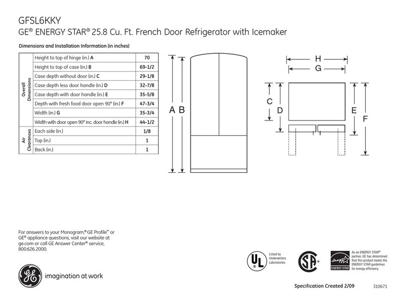
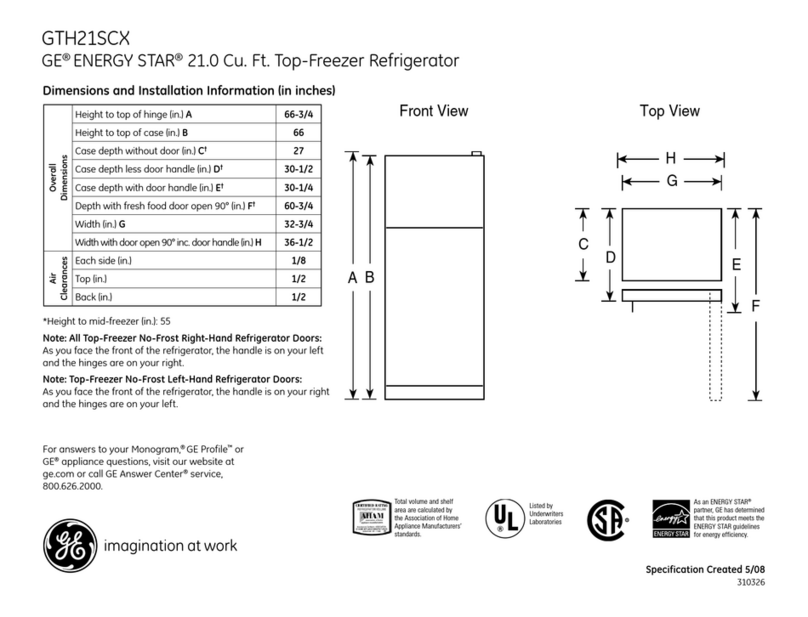
G/K2 PRODUCT DIMENSIONS
CURRENT GENERATION NEW GENERATION
Model TFG20 TFG22 TFG25 TPG24 TFK28 TPG30
Height 66.63” 66.63” 68.75” 68.75” 68.75” 68.75”
(169 cm) (169 cm) (175 cm) (175 cm) (175 cm) (175 cm)
Width 31.50” 33.50” 35.75” 35.75” 36.00” 35.75”
(80 cm) (85 cm) (91 cm) (91 cm) (91 cm) (91 cm)
Depth (including 32.50” 32.50” 32.50” 28.44” 33.50” 34.50”
handles) (83 cm) (83 cm) (83 cm) (72 cm) (85 cm) (88 cm)
Depth (no handles) 30.50” 30.50” 30.50” 26.38” 33.50” 34.50”
(77 cm) (77 cm) (77 cm) (67 cm) (85 cm) (88 cm)
MODEL NOMENCLATURE
TPG 24 PRZA
BRAND / PRODUCT ENGINEERING DESIGN / REVISION
T = GE Refrigerator A = Initial Design
B = First Revision
CONFIGURATION MODEL YEAR
F = Side-by-Side Z = 1997
P = Built-In Style
ENERGY ICEMAKER / DISPENSER / EXTERIOR
G = 230V @ 50 Hz A = Icemaker Ready
K = 220V @ 60 Hz R = Cube, Crushed & Water Dispenser
W = Cube & Water Dispenser
CAPACITY INTERIOR FEATURES / SHELVES
(cubic feet) AHAM Rated Volume P = Profile Line Features
J = Glass

1997 REFRIGERATORS GLOBAL NEW GENERATION
SxS
© General Electric Company 1997 3
NEW GEN (24’, 28’, 30’) - TFK / TPG PRODUCT LINE
FRONT VIEW
IMPROVEMENT CODING
(ES): EXTERNAL SWEAT
(C): CORROSION
(N): NOISE
(E): ENERGY
(F): FEATURE & APPEARANCE
(CB): CODE BOARD

1997 REFRIGERATORS GLOBAL NEW GENERATION
SxS
© General Electric Company 1997 4
(V): VOLTAGE/THERMAL
NEW GEN (24’, 28’, 30’) - TFK / TPG PRODUCT LINE
REAR VIEW
IMPROVEMENT CODING
(ES): EXTERNAL SWEAT
(C): CORROSION
(N): NOISE
(E): ENERGY
(F): FEATURE & APPEARANCE

1997 REFRIGERATORS GLOBAL NEW GENERATION
SxS
© General Electric Company 1997 5
(CB): CODE BOARD
(V): VOLTAGE/THERMAL
RATING PLATE
The rating plate is located at the top of the
fresh food liner, near the right front corner.
In addition to the refrigerator model and
serial numbers, the rating plate specifies the
minimum installation clearances; the electrical
voltage, frequency, and amperage ratings; and the
refrigerant type and charge quantity.
The model and serial numbers of the refrigerator
are also located on a bar-code label at the rear of
the cabinet.
KOREAN RATING PLATE (K-Line only)
The Korean rating plate is located on the right-
hand side of the outer cabinet. It shows KIAA
approval #, model #, total volume, fresh food
volume, freezer volume, motor input watts, defrost
heater watts and manufacture date (year/month).
ISO RATING PLATE
The ISO rating plate is located to the right of the traditional rating plate on the upper side of the fresh
food liner. Besides the model #, voltage, amperage, input watts, installation clearances, and refrigerant
charge, it contains unique information such as gross volume, freezing capacity, fresh food net volume,
freezer net volume, and frozen food storage area net volume. There is also a class designator which
identifies the ambient test condition range for its given ISO rating. On Korean models, the logos,
symbols or numbers for the international regulatory agencies/code boards that have approved the model
are shown.
KOREAN ENERGY LABEL (K-Line only)
The Korean energy label is located near the top of the outer fresh food door. It contains information
necessitated by two laws-- the Energy Consumption Control Law (upper half of label) and the Electric
Appliance Safety Control Law (lower half of label). The upper area has numbers ranging from 5 to 1,
where the lower the number, the better the energy rating. The lower half of the label specifies model
number, approval number, volume capacity, and monthly energy consumption.
MINI-MANUAL™
The Mini-Manual is located behind the base grille, at the left side, near the front of the machine
compartment. A plastic pin fastener is used to secure the Mini-Manual during shipping. Accordingly,
1997 REFRIGERATORS GLOBAL NEW GENERATION
SxS
© General Electric Company 1997 6
after the refrigerator has been installed in the consumer’s home, it is not necessary to reinstall the
fastener. After using the Mini-Manual, it should be returned to its original location for future use.
CABINET STRUCTURE
The outer case (top and sides) is made of prepainted steel with a textured finish. The fresh food and
freezer liners are made of prepainted steel with a smooth finish. The outer case and doors are
insulated with urethane foam.
A plastic breaker frame, fitted to the front of the
outer case and over the edges of the freezer and
fresh food liners, is foamed-in-place. This
reduces the transfer of heat from the room into
the freezer and fresh food compartments. The
breaker frame is not removable and not
replaceable.
The fresh food and freezer door gaskets are
compression type with fiberglass inserts
(rather than magnetic) because the breaker
frame, at the front flanges of the cabinet, is non-
magnetic.
Bar magnets mounted to the base channel and
steel strikes mounted to the bottom of the doors
hold the doors in a closed position. Soft pads
positioned over the strikes prevent damage to
shoes or injury to feet when the doors are
opened.
Externally, the most noticeable difference from
previous models is the rounded edges of the
freezer and fresh food doors −at the left and
right sides.
Internal features are similar to other 1994 side-
by-side Profile™ models. Cantilever glass
shelves are provided in the fresh food
compartment. The freezer compartment is
equipped with cantilever wire shelves and baskets.

1997 REFRIGERATORS GLOBAL NEW GENERATION
SxS
© General Electric Company 1997 7
Base Grille
The base grille is attached to the cabinet with two spring
steel retainers that grip into elongated openings of the
base channel. To remove the grille, pull it straight
forward.
Door Closure Mechanism
Door closure mechanisms assist in closing the
fresh food and freezer doors. The closure
mechanism consists of a lever, mounted with a
spring to the base channel, which interacts with a
cam mounted to the bottom of each door with two
screws. When the door is closed to about the 45°
position, the lever contacts the cam with a slight
amount of resistance. As the door is closed
further, a small roller in the end of the lever glides
over the lobe of the cam and pulls the door closed.
The levers and cams are specifically left-hand and
right-hand, but the springs are the same for both
sides.
To remove the levers and springs, first remove the
base grille. Then, grip the end of the spring firmly
with pliers and unhook it from the notch in the base
channel. (Slip-joint or locking type pliers are
recommended.) Grasp the spring and hold onto it
while pulling the lever and the spring through the
opening in the base channel. Unhook the spring
from the notch in the lever. Upon reinstallation,
grasp the spring and hold onto it while inserting the
spring and lever through the opening in the base
channel.

1997 REFRIGERATORS GLOBAL NEW GENERATION
SxS
© General Electric Company 1997 8
Rollers
Rollers at the base of the cabinet enable the consumer to easily move the refrigerator. The front rollers
are adjustable to permit leveling the cabinet. The adjustment screws, located behind the base grille,
have 3/8-inch hex-heads that are also slotted (for use of a large blade screwdriver). The rear rollers are
not adjustable.
To remove a front roller assembly from the base of the cabinet, tilt the cabinet and place 3-inch blocks
under the side of the outer case. Remove the three 1/4-inch hex-head screws to dismount the bracket.
Then, loosen the adjustment screw to disengage the nut and withdraw the roller assembly from the
cabinet.
Remove the E-Ring to disassemble the adjustment
screw from the base channel. Upon reinstallation of
the roller assembly, to facilitate installing the
adjustment screw, position the nut so that the flared
thread is toward the rear.

1997 REFRIGERATORS GLOBAL NEW GENERATION
SxS
© General Electric Company 1997 9
Door Hinges
Torx head (T-20) screws are used to mount the
top and bottom hinges for both doors.
Mounting holes in all four hinges are not
elongated. Accordingly, the hinges are not
adjustable. When reinstalling the hinges,
tighten the screws to 60 in-lbs. (6.8 newton-
meters). Avoid over-tightening to prevent
stripping.
The top hinges for the fresh food and freezer
doors are identical. However, the bottom
hinges are specifically left-hand and right-hand.
The bottom hinge pin for the fresh food door is
adjustable, up or down, to permit aligning the
fresh food door height evenly with the freezer
door. A hexagonal impression in the lower end
of the hinge pin allows use of a 3/16-inch Allen
wrench to adjust the pin. A nylon plug,
imbedded in the threads of the pin, prevents the
pin from rotating (tightening or loosening) as
the door is opened and closed.
The hinge pin at the bottom of the freezer door
is not adjustable.
Door Gaskets
The compression type gaskets are secured to
the fresh food and freezer doors with 2-sided tape. Once the gasket has been removed, it cannot be
reattached successfully. Accordingly, a new gasket will be required. When handling the replacement
gasket, avoid bending it to prevent creasing the sealing surface, which would result in an appearance
blemish.
To replace the gasket, first remove the door from the refrigerator and place it horizontally on a protected
surface. Then, beginning at one corner, peel the gasket from the door (a putty knife may be helpful in
releasing the gasket).

1997 REFRIGERATORS GLOBAL NEW GENERATION
SxS
© General Electric Company 1997 10
Tape residue on the retainer strips and screws is
difficult to remove and will prevent new tape from
adhering satisfactorily. Thus, new retainer strips
and screws are required when replacing a
gasket. Replace the retainer strips one-at-a-time.
When removing the retainer strips, do not remove
the inner door locator screws near the center of
all 4 strips. The locator screws do not secure the
strips but, rather, maintain the position of the
inner door on the outer door. When installing
each retainer strip, first drive one screw next to
the locator screw (either at the left or right).
Then, continue driving the remaining screws
(without skipping) from the center toward the
ends of the strip (to ensure the strips will be flat
against the inner door). After all screws are
driven, make sure all screw heads are below the
surface of the strips and that the surfaces of the
strips are clean.
Apply the 2-sided tape first to the side retainer
strips, then to the top and bottom strips. Keep
the tape back from the outer edges of the strips
about 1/16-inch to ensure the outer skirt of the
gasket will contact the outer door. Use a sharp
knife to cut the ends of the tape squarely. Butt
adjoining pieces of the tape at the corners; do
not overlap the tape (to prevent high spots).
Leave the protective ribbon on the surface of
the tape until after the gasket is positioned on
the door.
Place the gasket on the door so that the wide
dimension is at the hinge side (the gasket is not
symmetrical). Position the gasket so that the
outer skirt is evenly aligned on all sides.
Beginning at the top of the door, lift the gasket
and peel the protective ribbon back from both
corners about 1-inch and position the 4 ends of
the ribbon beyond the edge of the door.

1997 REFRIGERATORS GLOBAL NEW GENERATION
SxS
© General Electric Company 1997 11
Carefully position the gasket back on the door,
aligning the outer skirt with the edges of the door,
and press the corners to tack them to the
exposed tape. Then, pull the ribbon slowly from
between the tacked corners, pausing to press
(not rub) the gasket into the exposed tape at
about 2-inch intervals. Continue the process
next at the handle side of the door, then at the
hinge side, and last at the bottom of the door,
making sure the outer skirt is evenly aligned with
the edge of the door. Before reinstalling the
door, again press the gasket at 2-inch intervals
to ensure it is sealed to the tape along the top,
sides, and bottom.
ICEMAKER
The icemaker, located in the upper rear of the
freezer compartment, is mounted transversely to
the shelf tracks. It has a thermal cutoff and
produces ice cubes with rounded edges.
To remove the icemaker, first remove the ice bin
from the ice shelf. Then, remove the power cord
cover (on the back of the ice shelf, below the
icemaker) and disconnect the power cord.
Remove the screw that secures the icemaker to
the ice shelf and lift the icemaker off the shelf
tracks.
When reinstalling the icemaker, make sure the
fill tube extension is inserted into the fill cup 1/2”-
3/4” (1.3 cm-1.9 cm) before engaging the
mounting plate on the shelf tracks.
Water Valve
The dual water valve is mounted to a bracket that
is secured to the cabinet, inside the machine compartment, at the right rear corner. A short length of
copper tubing, connected to the valve inlet and extending out of the machine compartment, has a
compression type union to facilitate connecting the water line without removal of the rear access cover.

1997 REFRIGERATORS GLOBAL NEW GENERATION
SxS
© General Electric Company 1997 12
DISPENSER
In 1993, a completely new recess assembly in
the freezer door was introduced in all side-by-
side dispenser model refrigerators. These
models have a single pad (rather than cradles)
for dispensing water, crushed ice, or cubes.
The selection of water, crushed ice, or cubes is
made at the control console.
The major components of the water and ice
dispenser are:
•an ice bin assembly −on a shelf below the
icemaker.
•an auger motor assembly −at the rear of
the ice shelf.
•a water reservoir −in the fresh food
compartment. (Capacity- 32 oz, 950 ml.)
•a water valve −in the machine
compartment.
•a recess assembly −on the freezer door.
Ice Bin Capacities
Model Style Capacity
20’ Bucket 8.1 lbs (3.7 kg)
24’-27’ Bucket 10.8 lbs (4.9 kg)
30’ Bucket 12.9 lbs (5.6 kg)
24’ Single helix 8.4 lbs (3.8 kg)
Ice Shelf Assembly
To remove the ice shelf, first remove the ice bin
and the icemaker. Next, disconnect the ice shelf
wiring harness plug from the receptacle at the
left of the evaporator fan. Remove the light
shield by pulling it forward to disengage it from
the shelf rod. Remove the lamp (light bulb) at
the bottom of the ice shelf. Then, remove the
two screws at the bottom (that secure the ice
shelf to the shelf tracks) and lift the ice shelf off
the shelf tracks.
The auger motor and cube solenoid are mounted
to the rear of the ice shelf. The lamp socket for
the freezer light is mounted to the bottom of the
ice shelf.

1997 REFRIGERATORS GLOBAL NEW GENERATION
SxS
© General Electric Company 1997 13
Dispenser User Operation
On non-electronic models, water and ice
selections are made by positioning
the selector switch knob which is located at
the lower left side of the console. The
switch has a detent at each selection to
ensure positive positioning.
On electronic models, water and ice
selections are made by touching pads
which are located along the lower front
of the console. Indicator lights,
adjacent to the touch pads, verify the
selection that is made.
When dispensing ice, either crushed or
cubes, the duct door is opened by an
electrical solenoid as a glass is gently
pressed against the dispenser pad. After
the glass is withdrawn from the pad, the
duct door will remain open for 5 to 10
seconds to prevent the entrapment of ice
in the duct and chute. An audible “snap”
can be heard when the solenoid is
energized. Then, when the duct door
closes, a soft “pop” may also be heard.
On models that have a light in the
recess, the light will automatically be
illuminated when the dispenser pad is
pressed. The light can also be turned on
and off manually. On non-electronic
models, the light switch is located at
the lower right side of the console. On
electronic models, the light switch is
located below the console at the left
side.
The grille at the bottom of the recess
housing can be easily removed by
pressing downward at the right rear
corner.

1997 REFRIGERATORS GLOBAL NEW GENERATION
SxS
© General Electric Company 1997 14
Dispenser User Operation - Electronic System
A new control console was introduced on all 1993 models that had the electronic system. However, the
electronic monitor and diagnostic feature was similar to previous models.
1. Touch pads provide for the selection of “chilled water”, “crushed ice”, or “cubed ice”. A beep will
sound each time either pad is touched. A green indicator light verifies which selection has been
made.
2. The door alarm can be
enabled by touching
the “door alarm on/off”
pad. A beep will sound
each time the pad is
touched. A green
indicator light verifies
the alarm is enabled. A
beep will sound after the
fresh food or freezer
door has been open for
thirty seconds. The
beep will continue until
both doors are closed
or the alarm is disabled.
3. A red signal light
will flash any time
either the fresh food
or freezer door is
open or ajar more
than 1/4-inch. The
signal light will be
extinguished when
both doors are
closed.

1997 REFRIGERATORS GLOBAL NEW GENERATION
SxS
© General Electric Company 1997 15
4. A red signal light will appear when the freezer temperature is above normal. The signal light
will turn off when the temperature returns to normal.
NOTE: The freezer temperature sensor, located on the inner door, quickly responds to
changes in air temperature within the freezer compartment. Accordingly, threshold temperatures
of 1ºC (35ºF) and 13ºC (55ºF) are monitored by the electronic system at various time intervals to alert
the consumer before frozen foods begin to thaw.
5. The green lighted word “normal” indicates that no failure has been detected by the electronic
system monitor.
6. A flashing green diagnostic code will be displayed when a failure has been detected by the
electronic system. The first six flashes will be accompanied by a beep. If more than one
coded function requires attention at the same time, the highest priority code will be displayed
until erased. The codes, in order of priority, are:
FF - Freezer - check for thawing of frozen foods
PF - Power - power has been off for more than 2 seconds
CI - Icemaker - check ice bin for blockage
dE - Defrost - defrost system has failed
7. The “ system check/reset” provides
a review of all diagnostic codes in
order of priority. Touching the reset
pad will initiate the review. If no failure is
detected, the review sequence will
continue until the system is reset.
Touching the “system check/reset” pad
will erase the PF and CI codes.
However, the electronic system is
programmed to prevent the FF and dE
codes from being erased unless the
condition has been corrected. The FF
code can be erased only when the
freezer temperature is reduced to
normal. The dE code will automatically
be erased when defrost current is
detected by the electronic system.
SYSTEM CHECK/RESET
TOUCH:
OBSERVE:
DIAGNOSTIC CODE SEQUENCE FF, PF, CI, dE
& SIMULTANEOUS “NORMAL”
•“NORMAL” REMAINS LIT
- IF NO FAULT DETECTED
•DIAGNOSTIC CODE DISPLAYED
- IF FAULT DETECTED

1997 REFRIGERATORS GLOBAL NEW GENERATION
SxS
© General Electric Company 1997 16
DISPENSER SERVICE
All electrical components (except the recess heater) are easily accessible from the front of the door.
Accordingly, there is no service opening provided in the freezer inner door. Caution: disconnect the
power source to prevent an electrical shock hazard and/or inadvertent dispensing of water or ice while
servicing the dispenser.
Pad
To remove the pad, grasp it at one edge and
pull it forward to disengage the inner lip
(grommet) from the opening in the pad
support.
To reinstall the pad, position the inner lip into
the opening in the pad support, engaging the
rib at the top into the slot. Press the pad
firmly at the top, sides and bottom to seat
the lip.
Pad Support
To remove the pad support, first remove the
pad. Reach through the opening with
fingertips and gradually pull the support
forward at each corner to disengage the
molded pins from the recess housing.
Caution: excessive force applied at one
corner may result in breaking a molded pin
from the support.
To reinstall the pad support, first reinstall
the pad on the pad support. Position the
support so the slot is at the top of the
opening. Engage the molded pins into the
mounting holes and gradually press the
support at each corner until it is firmly
seated.
Escutcheon
To remove the escutcheon, insert the blade
of a putty knife behind the escutcheon at
the bottom. Twist the putty knife to
disengage the molded pins from the front
of the control housing.
To reinstall the escutcheon, position the
molded pins into the holes in thefront of the
control housing and press the escutcheon
firmly to seat the pins.

1997 REFRIGERATORS GLOBAL NEW GENERATION
SxS
© General Electric Company 1997 17
Control Housing
To remove the control housing -- first
remove the pad, the pad support and the
escutcheon. Then, remove the screws at
the front of the housing. Pull the
housing forward about 1-inch and
disconnect the 6-wire harness connector
from the left end of the control module
(printed circuit board).
To reinstall the control housing --
reconnect the 6-wire harness connector to
the control module. Push the control
housing firmly into position and
reinstall the screws. Then, reinstall
the escutcheon, pad support and pad.
Control Module
To remove the control module -- first
remove the control housing. Then, remove
the knobs from the selector switch and
light switch by pulling them straight
downward. Disconnect the 4-wire harness
connector from the control module.
Remove the screws at the ends of the
cover and lift the cover from the control
housing. Grasp the edges of the control
module and lift it out of the slots in
the control housing.
To reinstall the control module --
position it into the slots in the control
housing so that the 4-pin connector is at
the end nearest the 4-wire harness
connector. Then, reinstall the cover.
Reconnect the 4-wire harness connector to
the control module and dress the harness
downward to prevent pinched wires when
the control housing is reinstalled.
Reinstall the switch knobs, control
housing, escutcheon, pad support, and
pad.

1997 REFRIGERATORS GLOBAL NEW GENERATION
SxS
© General Electric Company 1997 18
Lamp Socket
To remove the lamp socket -- first
remove the control housing. Then,
disconnect the wiring harness from the
lamp socket. Compress the tabs at the
sides of the socket and withdraw the
socket and lamp reflector from the
bottom of the control housing.
To reinstall the lamp socket --
position it inside the reflector,
aligning the ribs and tabs with the
slots in the reflector. Then,
position the socket and reflector into
the cavity in the control housing and
press the socket firmly to lock the
tabs. Reinstall the wiring harness,
control housing, escutcheon, pad
support and pad.
Pad Switch
To remove the pad switch -- first
remove the control housing. Then,
disconnect the wiring harness from the
switch. Remove the screw at the
bottom of the switch and slide the
switch off of the the mounting pin.
To reinstall the pad switch --
position it on the mounting pin so
that the terminals are at the top and
the switch lever is toward the rear,
but in front of the actuator paddle.
Then, reinstall the screw at the
bottom of the switch and reconnect the
wiring harness. Caution: check the
position of the switch lever to verify
that it is in front of the actuator
paddle by rotating the actuator and
observing the operation of the switch.
Reinstall the control housing,
escutcheon, pad support and pad.

1997 REFRIGERATORS GLOBAL NEW GENERATION
SxS
© General Electric Company 1997 19
Pad Switch Actuator
To remove the pad switch actuator--
first remove the control housing. Then,
press the actuator out of the notch and
hole at the rear of the control housing.
To reinstall the pad switch actuator--
position it into the hole and notch at the
rear of the control housing so that the
actuator paddle is behind the switch
lever. Firmly press the actuator to seat
it into the notch. Caution: verify
operation of the switch by rotating the
actuator. Reinstall the control housing,
escutcheon, pad support, and pad.
Ice Deflector
To remove the ice deflector-- remove
the control housing and the pad switch
actuator. Grasp the rear edge of the
ice deflector and pull it from the control
housing.
To reinstall the ice deflector-- position
the flap below the rear edge of the ice
funnel and engage the channel over the
rear edge of the control housing. Press
This manual suits for next models
7
Table of contents
Other GE Refrigerator manuals

GE
GE 22 Safety guide

GE
GE SIDE-BY-SIDE REFRIRATOR 22 Installation instructions

GE
GE ZS48N User manual

GE
GE GTE15 Series User manual

GE
GE GTS22KHP User manual

GE
GE Monogram ZFSB25DMASS User manual

GE
GE TBF21R Installation instructions

GE
GE GTH21SBXSS User manual

GE
GE TBX16SIBAA User instructions

GE
GE Profile CustomStyle PSC23PSTSS Manual

GE
GE GTL12HBXRBS Manual

GE
GE PSC21MGM How to use

GE
GE Cafe CFCP1NIZSS Manual

GE
GE GTU358BAMR User manual

GE
GE GTH21SBWSS Manual

GE
GE TOP-FREEZER 16 User manual

GE
GE GTL18JCPBS User manual

GE
GE GSF25TGTBBB and Safety guide

GE
GE GE Profile Arctica PSS27NGN User instructions

GE
GE GE Profile Arctica PTS22LHP User instructions