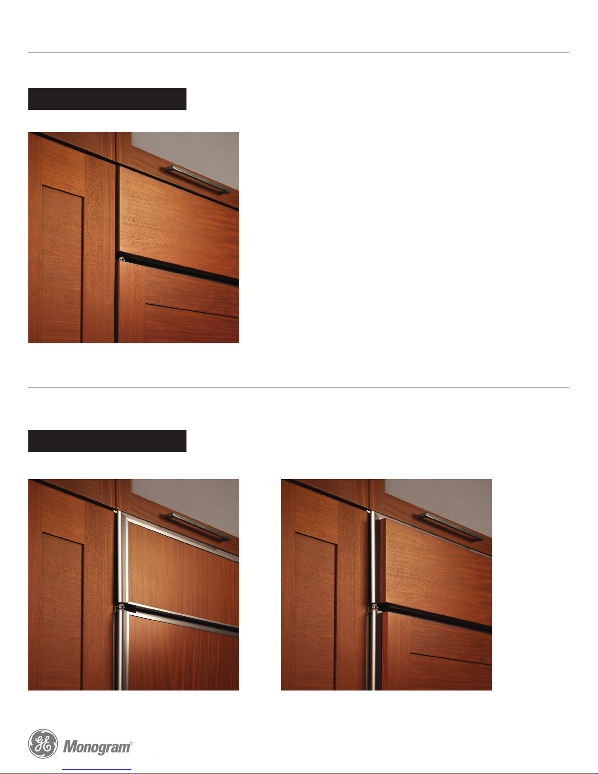
PANEL ASSEMBLY CROSS SECTION
PANEL ASSEMBLY CROSS SECTION
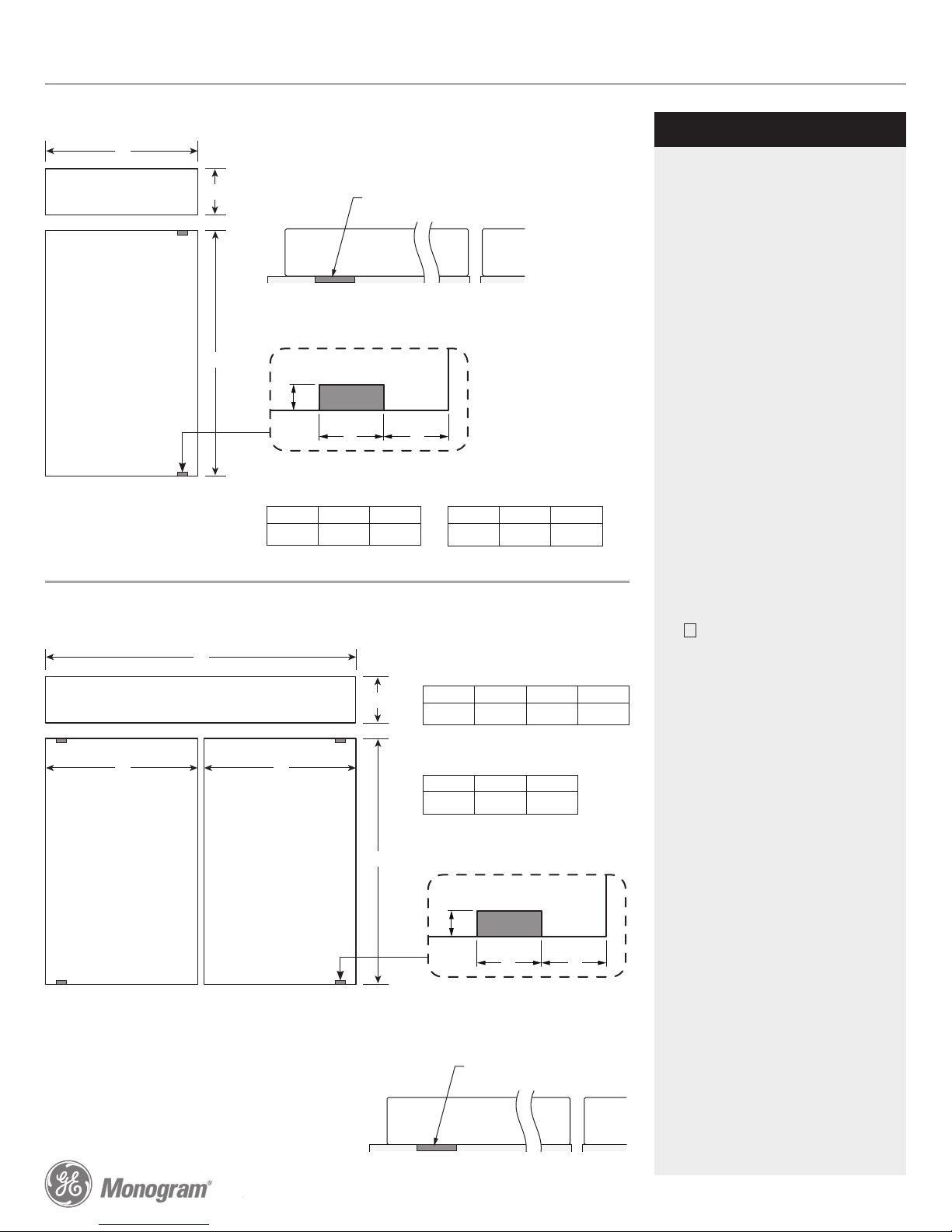
PANEL DIMENSIONS
PANEL DIMENSIONS
.25" + .10" + .75" = 1.10" Total Panel Thickness
NOTES
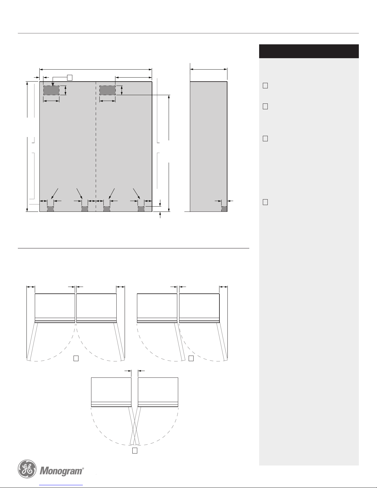
STANDARD INSTALLATION
Product Specification Revised 10/14
Trimmed refrigerators are designed to be
customized with decorative panels. Field-
installed custom door and grille panels are
required.
1/4” Framed Panels:
Order trim kit #ZTK36SDHRH
for 1/4" thick custom panels ordered from
your cabinet maker. The decorative panels
slide into the trim.
Maximum total panel weight:
• Door panel – 67 lbs.
• Grille panel – 11 lbs
3/4” Overlay Panels:
Order trim kit #ZTK36SDHRH
for 3/4" thick custom panels ordered from
your cabinet maker. The decorative panels
slide into the trim. The overlay panel must be
secured to a 1/4"-thick backer panel which
slides into the trim. A spacer panel 0.10" thick
must be placed between the overlay and
backer panels.
Center each panel over the other. Assemble
the panels with glue and screws. Screws must
be countersunk into the backer panel.
NOTE: Left-to-right offset is not always equal
to top-to-bottom offset.
Maximum total panel weight:
• Door panel – 67 lbs.
• Grille panel – 11 lbs
Door Handles:
The supplied handles can be adjusted to
accommodate both framed or overlay panels.
Custom handles of your choice, supplied by
your cabinet maker, can also be installed.
ZKHPSS1: Professional Tubular Stainless Steel
Handle designed to fit 3/4" overlay panels.
Kits include one handle - 30 1/2" long.
ZKHSS2: European tubular stainless steel
handle designed to fit 3/4" overlay panels.
Kits include one handle - 64 1/4" long.
ZIR360NHRHGE Monogram®36" Built-In All-Refrigerator
3/4" OVERLAY PANEL DIMENSIONS SINGLE INSTALLATION
1/4" FRAMED PANEL DIMENSIONS SINGLE INSTALLATION
ABC
1/4" Backer Panel 33 7/8" 8 7/8" 69 5/16"
.10" Spacer Panel 32 1/2" 7 5/8" 67 15/16"
3/4" Overlay Panel 34 1/8" 9" 69 9/16"
ABC
1/4" Framed Panel 33 7/8" 8 7/8" 69 5/16"
Grille Panel
Door
Panel
A
B
C
Grille Panel
Door
Panel
B
C
Door
Supplied Handles
Trim
Door
1/4" Backer Panel
.10" Spacer Panel
Supplied Handles
Trim
3/4" Overlay Panel