Gefen GTV-HT-AUDPROC User manual

Home Theater Audio Processor
User Manual
www.gefentv.com
GTV-HT-AUDPROC


ASKING FOR ASSISTANC
E
T
echnical Su
pp
or
t
:
Telephone
(
818
)
772-910
0
(
800
)
545-690
0
Fax
(
818
)
772-912
0
T
echnical Su
pp
ort Hours
:
8
:00 AM to 5:00 PM P
S
T Monda
y
thru Frida
y
.
Write To
:
G
e
f
en, LL
C
c/
o
C
ustomer
S
ervic
e
2
0600
Nordho
ff
S
t
C
hatsworth,
C
A 9131
1
www.
g
e
f
entv.com
s
upport
@g
e
f
entv.com
Notic
e
G
e
f
en, LL
C
reserves the ri
g
ht to make chan
g
es in the hardware, packa
g
in
g
, and
an
y
accompan
y
in
g
documentation without prior written notice.
G
efenTV Home Theater Audio Processor is a trademark o
f
G
e
f
en, LL
C
M
anu
f
actured under license
f
rom Dolb
y
Laboratories.
“
Dolb
y
”,
“
Pro Lo
g
ic”, and the double-D s
y
mbol are trademarks o
f
Dolb
y
Laboratories.
©
2011
G
e
f
en, LL
C
. All ri
g
hts reserved.
H
DMI, the HDMI Lo
g
o, and Hi
g
h-De
fi
nition Mulitmedia Inter
f
ace are trademarks
or re
g
istered trademarks o
f
HDMI Licensin
g
LL
C
in the United
S
tates and other
cou
ntri
es
.
All trademarks are the propert
y
o
f
their respective companies.
Rev A
6

CONTENT
S
1 Intr
oduc
ti
on
2
O
peration Notes
3
Features
4 Panel La
y
ou
t
5
Panel Descriptions
8
C
onnectin
g
The Home Theater Audio Processor
9
G
TV-AUD-IR Remote La
y
ou
t
10
G
TV-AUD-IR Remote Descriptions
11
G
TV-A
U
D-IR Remote Installatio
n
11 H
o
m
e
Th
ea
t
e
r A
ud
i
o
Pr
ocesso
r R
e
m
o
t
e
In
s
t
a
ll
a
ti
on
12
O
peratin
g
the Home Theater Audio Processor
20
S
peaker Format Tabl
e
22 Bi-Ampin
g
2
3
RS
-2
32
S
erial
C
ontrol Inter
f
ac
e
24 R
S
-2
3
2
C
ommands
28
S
peci
fi
cations
29 Warrant
y

1
C
on
g
ratulations on
y
our purchase o
f
the
G
e
f
enTV Home Theater Audio
Processor. Your complete satis
f
action is ver
y
important to us.
G
efenTV
G
e
f
enTV is a unique product line caterin
g
to the
g
rowin
g
needs
f
or innovative
h
ome theater solutions.
G
e
f
en specializes in total inte
g
ration
f
or home theater
c
onnectivit
y
, while also
f
ocusin
g
on
g
oin
g
above and be
y
ond customer
e
xpectations to ensure
y
ou
g
et the most
f
rom
y
our hardware.
G
e
f
en invites
y
ou
to explore the distinct
G
e
f
enTV product line and hope that
y
ou
fi
nd the solution
that
fi
ts
y
our needs.
T
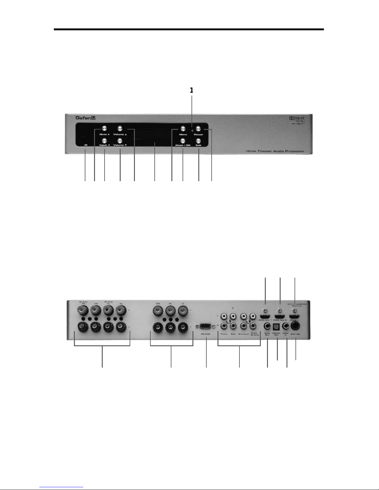
he GefenTV Home Theater Audio Processor
The
G
e
f
enTV Home Theater Audio Processor is a power
f
ul
y
et ver
y
compact
s
olution
f
or all
y
our audio
/
video needs.
The
G
e
f
enTV Home Theater Audio Processor provides pass-throu
g
h connection
f
or a Hi-De
f
source to two mirrored HDTV displa
y
s usin
g
HDMI
f
eatures
s
upportin
g
1080p
f
ull HD, Deep
C
olor, Lip-
Sy
nc, Dolb
y
TrueHD, DT
S
-HD MA,
and 3DTV pass-throu
g
h. The audio
f
rom both the HDMI and coax inputs is sent
to the coax and optical outputs as compressed A
C
-3 di
g
ital audio and to separate
s
ix-channel audio on the R
C
A and bindin
g
post connectors. Up to 5.1 channels o
f
LP
C
M, Dolb
y
Di
g
ital, and Dolb
y
Pro Lo
g
ic II is decoded on the output.
S
peakers can be connected to the bindin
g
posts usin
g
the built-in ampli
fi
er,
deliverin
g
25 watts per channel RM
S
. The audio can also be sent to an external
p
ower ampli
fi
er usin
g
the R
C
A connectors. The
f
ront-le
f
t and
f
ront-ri
g
ht channels
u
se bi-ampli
fi
cation to enhance the sound qualit
y
.
The Home Theater Audio Processor
f
eatures an eas
y
-to-read L
C
D displa
y
with
e
xtensive
f
eatures such as individual control o
f
speaker size, distance location,
and volume up
/
down.
C
ontrol is available usin
g
the
f
ront panel push buttons or
u
sin
g
the included IR remote and R
S
-232 control.
How It Works
C
onnect the
G
e
f
enTV Home Theater Audio Processor to the Hi-De
f
source usin
g
the supplied HDMI cable and coax cable.
C
onnect up to two
(
2
)
HDTV displa
y
s
or AV receivers to the Audio Processor HDMI outputs.
C
onnect an optical and
a coax cable
f
rom the Audio Processor di
g
ital audio outputs to an AV receiver.
U
se the bindin
g
posts to connect up to
fi
ve speakers. The sub-woo
f
er must be
a powered version and is connected to the R
C
A connector allocated
f
or the sub.
C
onnect the included 24V power suppl
y
to the Audio Processor and push the
p
ower button to turn on the Audio Processor. Appl
y
power to the Hi-De
f
source
and HDTV Displa
y(
s
)
and
/
or AV receivers.
INTRODUCTIO
N

2
READ THESE NOTES BEFORE INSTALLING OR
OPERATING THE HOME THEATER AUDIO PROCESSOR
• The
G
e
f
enTV Home Theater Audio Processor is desi
g
ned to be used with
s
peakers, usin
g
fi
ve
f
ull-bandwidth channels and one low
f
requenc
y
channel.
RC
A outputs are provided
f
or connectin
g
the
G
e
f
enTV Home Theater Audio
Processor to a separate audio ampli
fi
er. Two
(
2
)
additional connectors, both
s
peaker and R
C
A, are available
f
or bi-ampin
g
the
f
ront-le
f
t and
f
ront-ri
g
ht
c
hannels
(
see pa
g
e 22
f
or details
)
.
• This unit provides a maximum power output o
f
25 Watts per channel RM
S
.
• This product supports the
f
ollowin
g
audio
f
ormats
:
LP
C
M
(
up to 6 channels
)
Dolb
y
Di
g
ital
(
A
C
-3 up to 6 channels
)
Dolb
y
Pro Lo
g
ic
Dolb
y
Pro Lo
g
ic II
OPERATION NOTE
S

3
Su
pp
orted HDMI 1.3 Features
• 225 MHz
(
up to 12-bit YUV 4:4:4
@
1080p
)
• Deep
C
olor support
(
x.v.
C
olor
)
• Lip-
Sy
nc pass-throu
gh
•
C
E
C
pass-throu
gh
Features
•
S
eparates di
g
ital audio
f
rom the HDMI or o
f
S/
PDIF inputs and decodes up
to 5.1 channels o
f
di
g
ital audi
o
•
S
plits one HDMI input source into 2 mirrored HDMI outputs
•
S
upported audio
f
ormats
:
Dolb
y
Di
g
ital, Dolb
y
Pro Lo
g
ic, and Dolb
y
Pro Lo
g
ic II decodin
g
• Test tone
f
or s
y
stem dia
g
nostics
•
O
utputs line-level analo
g
audio up to 5.1 channels usin
g
R
C
A connectors
•
O
utputs ampli
fi
ed analo
g
audio at 25 Watts per channel RM
S
on external
s
peaker terminals
• L
C
D status displa
y
f
or
f
ull selection men
u
• IR
co
ntr
o
l
•
RS
-2
3
2 control
• Field-up
g
radable
fi
rmwar
e
• External
/
Internal EDID mana
g
emen
t
•
S
mall in siz
e
• This product is HDMI and HD
C
P-complian
t
P
acka
g
e Includes
(
1
)
G
e
f
enTV Home Theater Audio Processor
(
1
)
6
f
t. HDMI cable
(
M-M
)
(
1
)
6
f
t.
S/
PDIF cabl
e
(
1
)
IR remote control
(
batter
y
included
)
(
1
)
24V D
C
Power
S
uppl
y
(
1
)
User Manual
FEATURE
S

4
Back
Fron
t
22 2
1
20
1917 1
8
1
6
151
4
1
3
12
P
ANEL LAYOU
T
1
1
1
7
8
9
105
4
3
2
6

5
1
P
ower Status LED Indicato
r
This LED will indicate the current power state. When the LED is red, the unit is
in standb
y
mode. When the LED is
g
reen, the unit is on.
2
I
nfrared Senso
r
This in
f
rared sensor will accept commands
f
rom the included
G
TV-AUD-IR
r
emote control. This sensor requires line-o
f
-si
g
ht between the unit and remote
f
or proper operation.
3
M
ute
/
Right Button
This button will c
y
cle between Mute-
O
n and Mute-
Off
modes when not in the
M
enu
Sy
stem. When the Mute-
O
n mode is enabled, all audio output will be
c
eased. While in the Menu
Sy
stem this button will c
y
cle throu
g
h available
options in the ri
g
ht direction when a
f
eature has been selected
f
or ad
j
ustment.
4
I
nput / Left Button
This button will to
gg
le between the HDMI and
C
oaxial audio input sources
when not in the Menu
Sy
stem. When the HDMI source is selected, audio will
be extracted
f
rom the embedded audio within the incomin
g
HDMI si
g
nal. When
the
C
oaxial source is selected, audio will be extracted
f
rom the incomin
g
audio
s
ource connected to the
C
oaxial
(S/
PDIF
)
input port. While in the Menu
Sy
stem
this button will c
y
cle throu
g
h available options in the le
f
t direction when a
f
eature
h
as been selected
f
or ad
j
ustment.
5
V
olume Decrease
/
Down Button
This button is used to decrease the volume level o
f
the audio outputs when
n
ot in the Menu
Sy
stem. While in the Menu
Sy
stem this button will c
y
cle down
throu
g
h the current level
’
s options.
6
V
olume Increase
/
Up Button
This button is used to increase the volume level o
f
the audio outputs when not
in the Menu
Sy
stem. While in the Menu
Sy
stem this button will c
y
cle up throu
g
h
the current level
’
s options.
7
M
ain LCD Displa
y
This displa
y
will show pertinent status in
f
ormation and will be used to make
ad
j
ustments to
f
eatures in the Menu
Sy
stem.
8
M
enu Button
This button will activate the Menu
Sy
stem which is where all ad
j
ustment and
s
ettin
g
s will be made.
P
ANEL DESCRIPTION
S

6
P
ANEL DESCRIPTION
S
9
M
ode / OK Button
This button will chan
g
e the Processin
g
Mode when not in the Menu
Sy
stem.
While in the Menu
Sy
stem this will be used as a con
fi
rmation button.
10
Exit Button
This button is used to exit the current menu level and return to the previous
/
p
arent level. This button will exit the entire Menu
Sy
stem when on the top most
le
v
e
l.
11
P
ower Button
This button will to
gg
le between the
O
N and
S
TANDBY power states. An LED
s
tatus indicator will si
g
ni
fy
the current power state. A RED LED will be active
when the unit is in
S
tandb
y
power state. A
G
REEN LED will be active when the
u
nit is in the
O
N power state.
1
2 Front Right and Front Left Speaker Terminal
s
These are 5-wa
y
bindin
g
post t
y
pe terminals. The
y
will accept spade lu
g
,
banana plu
g
, dual banana plu
g
, bare wire, and pin st
y
le connections. 4 pairs o
f
p
ositive and ne
g
ative terminals are available. 2 pairs are
f
or
f
ront ri
g
ht and
f
ront
l
e
f
t speakers. An additional 2 pairs are also available
f
or bi-ampin
g
the
f
ront ri
g
ht
and
f
ront le
f
t speakers.
13
C
enter, Surround Right, and Surround Left Speaker Terminal
s
These are 5-wa
y
bindin
g
post t
y
pe terminals. The
y
will accept spade lu
g
,
banana plu
g
, dual banana plu
g
, bare wire, and pin st
y
le connections. 3 pairs o
f
p
ositive and ne
g
ative terminals are available. 2 each
f
or the center, surround
r
i
g
ht, and surround le
f
t speakers.
14
R
S-232 Serial Communications Por
t
This port is used to control
f
unctions and
f
eatures usin
g
serial communications.
For more in
f
ormation on this
f
eature please see pa
g
e 23.
15
Analog Audio RCA Output
s
8
R
C
A t
y
pe audio outputs are available
f
or connection to a separate ampli
fi
er.
U
p to 6 discrete channels can be utilized. 2 R
C
A audio output connectors are
available
f
or
f
ront channel bi-ampin
g
purposes. Please see pa
g
e 22
f
or more
in
fo
rm
a
ti
o
n.
16
C
oaxial
(
S/PDIF
)
Audio Outpu
t
This output is constantl
y
active. Audio that is extracted
f
rom the input HDMI
s
ource device or via the coaxial input is directl
y
output throu
g
h this connector.
Processin
g
and
f
eatures o
f
the Home Theater Audio Processor are not applied
to the audio passin
g
throu
g
h this connector.

7
P
ANEL DESCRIPTION
S
17
Optical
(
TOSLINK
)
Audio Outpu
t
This output is constantl
y
active. Audio that is extracted
f
rom the input HDMI
s
ource device or via the coaxial input is directl
y
output throu
g
h this connector.
Processin
g
and
f
eatures o
f
the Home Theater Audio Processor are not applied
to the audio passin
g
throu
g
h this connector.
1
8
C
oaxial
(
S/PDIF
)
Audio Inpu
t
A coaxial audio source can be connected and used as the main audio input
s
ource i
f
desired. Please be aware o
f
the limitations o
f
audio t
y
pes and qualit
y
which can be transported over this connector t
y
pe.
19
2
4V DC Power Receptacle
This 24V D
C
power suppl
y
included with the unit connects to this receptacle.
Please onl
y
use the power suppl
y
that is included with this product.
20
HDMI Input Por
t
This input will accept a sin
g
le HDMI source device. Audio in the source
’
s si
g
nal
will be extracted and processed. This input will be replicated and output throu
g
h
the HDMI 1
&
2 ports. Audio
f
rom this source can be b
y
passed b
y
usin
g
the
audio
f
rom the coaxial input connector.
21
HDMI Output Port 1
This output will accept a sin
g
le HDMI output device. The HDMI input source will
be replicated and output throu
g
h this port and the HDMI output port 2.
2
2 HDMI Output Port 2
This output will accept a sin
g
le HDMI output device. The HDMI input source will
be replicated and output throu
g
h this port and the HDMI output port 1.

8
How to Connect the Home Theater Audio Processor
1.
C
onnect an HDMI source device to the HDMI input port o
f
the Home Theater
Audio Processor usin
g
the included HDMI cable.
2.
O
ptionall
y
, connect an additional audio source to the coaxial
(S/
PDIF
)
input
u
sin
g
a user supplied coaxial cable.
3
.
C
onnect up to 6 speakers to the speaker terminals on the back panel o
f
the Home Theater Audio Processor. The
f
ollowin
g
connection terminals are
a
v
a
il
ab
l
e:
•Fr
o
nt L
eft
• Front Le
f
t
(f
or bi-ampin
g)
• Front RI
g
h
t
• Front Ri
g
ht
(f
or bi-ampin
g)
•
C
enter
•Le
f
t
S
urroun
d
•
R
i
g
ht
S
urroun
d
4.
C
onnect the Di
g
ital Audio Decoder to an ampli
fi
er usin
g
the R
C
A connectors
on the rear panel. The
f
ollowin
g
R
C
A connectors are available
:
•Fr
o
nt L
eft
• Front Le
f
t
(f
or bi-ampin
g)
• Front RI
g
h
t
• Front Ri
g
ht
(f
or bi-ampin
g)
•
C
enter
•Le
f
t
S
urroun
d
•
R
i
g
ht
S
urroun
d
•
S
ubwoo
f
er
5
.
C
onnect up to two HDMI output devices to the HDMI outputs usin
g
user
s
upplied HDMI cables. I
f
onl
y
usin
g
a sin
g
le HDMI device, connect this
device to the HDMI
O
utput 1 port. These outputs will be mirrored.
6
.
O
ptionall
y
, audio can also be output usin
g
the coaxial
(S/
PDIF
)
and optical
(
T
OS
LINK
)
connectors. These outputs will not have an
y
processin
g
applied
t
o
th
e
m.
7. External control can be accomplished usin
g
the R
S
-232 serial
c
ommunications port. More in
f
ormation on the use o
f
this connector can be
f
ound on pa
g
e 23.
8
.
C
onnect the included 24V D
C
power suppl
y
to the power receptacle on the
H
ome Theater Audio Processor.
C
onnect the wall plu
g
into an empt
y
wall
p
ower socket.
CONNECTING TH
E
HOME THEATER AUDIO PROCESSOR

9
G
TV-AUD-IR REMOTE LAYOU
T
7
8
10
9
1
1
12
1
3
1
4
15
6
5
3
4
2
1
Home Theatre Audio Processor Remote Control

10
G
TV-AUD-IR REMOTE DESCRIPTION
S
1
P
ower Of
f
This is a discrete power o
ff
button. Pressin
g
this button will turn the Home
Th
ea
t
e
r A
ud
i
o
Pr
ocesso
r
off
.
2
M
ode
This button
f
unctions the same as the Mode button on the
f
ront panel.
3
L
ef
t
This button will navi
g
ate le
f
t when usin
g
the Menu
Sy
stem.
4
Exi
t
This button
f
unctions the same as the Exit button on the
f
ront panel.
5
M
ute
This button c
y
cle between mute on and mute o
ff
modes. When mute is applied
there will not be an
y
audio output.
6
S
/PDIF
This is a discrete button that will select the
S/
PDIF audio input source.
7
HDMI
This is a discrete button that will select the HDMI audio input source.
8
I
nfo/Test Tone
This button will displa
y
a series o
f
in
f
ormation messa
g
es on the L
C
D screen
when pressed. When ad
j
ustin
g
the
S
peaker Level, this button will activate a test
tone that is use
f
ul
f
or ad
j
ustin
g
the volume level o
f
each speaker.
9
V
olume Down
This button will navi
g
ate down throu
g
h options when usin
g
the Menu
Sy
stem
and will increase the volume when not in the Menu
Sy
stem.
10
Enhance
This button will c
y
cle throu
g
h the various enhancement modes. For a
f
ull
description o
f
these modes please see pa
g
e 18.
11
Ente
r
This button will con
fi
rm options and chan
g
es made in the Menu
Sy
stem.
1
2
R
igh
t
This button will navi
g
ate ri
g
ht when usin
g
the Menu
Sy
stem.
13
V
olume Up
This button will navi
g
ate up throu
g
h options when usin
g
the Menu
Sy
stem and
will increase the volume when not in the Menu
Sy
stem.
14
P
ower On
This is a discrete power on button. Pressin
g
this button will turn the Home
Th
ea
t
e
r A
ud
i
o
Pr
ocesso
r
o
n.
15
M
en
u
This button
f
unctions the same as the Menu button on the
f
ront panel.

1
1
To use the
G
TV-AUD-IR remote, remove the batter
y
cover on the back o
f
the remote
to reveal the batter
y
compartment. Insert the included batter
y
into the open batter
y
s
lot. The positive
(
+
)
side should be
f
acin
g
up. Ensure that both DIP
(
Dual Inline
Packa
g
e
)
switches are in the
O
FF position. Replace the batter
y
cover. The remote
s
hips with 2 batteries.
O
ne batter
y
is needed
f
or operation and the other batter
y
is
c
omplimentar
y
.
The DIP
S
witches above are used to set the IR
C
hannel.
C
han
g
in
g
channels will
alleviate issues that ma
y
occur i
f
the unit or remote control responds or inter
f
eres
with other non-
G
e
f
en equipment. This settin
g
must match the IR
C
hannel settin
g
on
the unit. Please see pa
g
e 18
f
or settin
g
up the IR
C
hannel on the unit.
1
2
R
emote
C
hannel 1
:
1
2
R
emote
C
hannel 2
:
1
2
R
emote
C
hannel
3:
1
2
R
emote
C
hannel 4
:
GTV-AUD-IR REMOTE INSTALLATIO
N
D
i
p
Switches
E
mpt
y
Batter
y
Slo
t

12
N
AVIGATION
The Home Theater Audio Processor uses a series o
f
buttons, located on the
f
ront
p
anel,
f
or all input selection and
f
eature
f
unctions. All status in
f
ormation, such as
the input audio t
y
pe, are alwa
y
s available on the
f
ront panel
L
CD Screen
.
U
ser
ad
j
ustable
f
eatures, such as speaker distance and processin
g
modes, can be
n
avi
g
ated and ad
j
usted b
y
re
f
erencin
g
the
LCD
Screen
.
All menu navi
g
ation and ad
j
ustments are accomplished b
y
usin
g
the
f
ront panel
buttons or the included
G
TV-A
U
D-IR remote control. Please review the
f
ront
p
anel buttons below.
For a
f
ull description o
f
each o
f
these buttons please see the descriptions on
p
a
g
e 5.
LCD SCREEN
Th
e
L
CD Screen displa
y
s status in
f
ormation and can also be used to navi
g
ate
and ad
j
ust
f
unctions when usin
g
the Menu
Sy
stem. This displa
y
is a hi
g
h contrast
2-line
/
16-character L
C
D. It will displa
y
in
f
ormation like in the example below
.

1
3
OPERATING THE HOME THEATER AUDIO PROCESSOR
MAIN DISPLAY
Th
e
M
ain Screen will displa
y
use
f
ul in
f
ormation to the user. It displa
y
s the
c
urrentl
y
selected input port and audio input
f
ormat. The currentl
y
used output
f
ormat can also be displa
y
ed b
y
pressin
g
the
▼
button. Pressin
g
the ◄or ►
bu
tt
o
n
s
whil
e
o
n thi
s
sc
r
ee
n will h
a
v
e
n
o
effec
t. Pl
ease
see
be
l
o
w
fo
r th
e
M
ain
Screen
l
a
y
out.
2
3
4
1 This section will displa
y
the currentl
y
selected audio input source.
2 This section will displa
y
the current volume level. The ran
g
e is
f
rom -60dB to
+
1
0
dB
3
The section will displa
y
the current input audio
f
ormat. This unit will support
LP
C
M
(
2-6
)
channels
)
and Dolb
y
Di
g
ital
(
A
C
-3 up to 6 channels
)
.
4 This section will displa
y
the current processin
g
mode.
S
upported modes are
Direct,
S
tereo, Multi
C
hannel
S
tereo, Mono, and Dolb
y
Pro Lo
g
ic II.
1 - INPUT SOURCE
This portion o
f
the screen will displa
y
the currentl
y
selected input. The available
inputs and their labels are listed below
:
L
CD Displa
y
Nam
e
Actual In
p
u
t
L
ocation
H
DMI
H
DMI In
Rea
r P
a
n
e
l
S
PDIF
(
de
f
ault
)
C
oax I
n
Rea
r P
a
n
e
l
To switch between audio input sources, use the
f
ront panel button labeled INPUT.
The IR remote control has discrete switchin
g
f
unctions. To select the source
c
onnected to the
“C
oax In” port, press the
S
PDIF button. To select the source
c
onnected to the
“
HDMI In” port, press the HDMI button.
2 - VOLUME INDICATOR
This portion o
f
the screen will displa
y
the current volume level. Volume control is
based on re
f
erence levels. 0.0dB on this unit is approximatel
y
85dB
(
re
f
erence
l
evel
f
or dialo
g
recorded in studios
)
with peaks o
f
up to 105dB.
The maximum volume settin
g
is +10dB. The minimum volume level is -60dB.
The de
f
ault value is -
30
dB.

1
4
3 - AUDIO FORMAT
This portion o
f
the screen will displa
y
the current audio inputs
f
ormat. Please use
the table below to determine what
f
ormats are accepted b
y
each input t
y
pe.
In
p
u
t
Su
pp
orted Audio Formats Su
pp
orted Channels
H
DMI
LP
C
M
6
Dolb
y
Di
g
ital
6
Dolb
y
Pro Lo
g
ic II
6
C
oaxial
LP
C
M
2
Dolb
y
Di
g
ital
6
Dolb
y
Pro Lo
g
ic II
6
4 - PROCESSING MODE
This portion o
f
the screen will displa
y
the currentl
y
used processin
g
mode.
M
ultiple processin
g
modes are provided to enhance the audio experience.
The
f
ollowin
g
processin
g
modes are available
:
• Direct - This mode will pla
y
back audio without an
y
processin
g
(
de
f
ault
)
.
•
S
tereo - This mode will pla
y
back all audio at 2 channels. Multiple channel
audio will be down-mixed appropriatel
y
.
•
M
ulti
C
hannel
S
tereo - The
f
ront ri
g
ht and le
f
t channels will be mixed and
also pla
y
ed back throu
g
h the center channel speaker. This mode is onl
y
available when usin
g
stereo sources. I
f
this mode is selected and a multi-
c
hannel source is detected, the mode will automaticall
y
switch to Direct
mode
.
•
M
ono - Audio
f
rom the
f
ront ri
g
ht channel will be pla
y
ed throu
g
h both the
f
ront ri
g
ht and
f
ront le
f
t speakers. I
f
a center channel speaker is available,
the
f
ront ri
g
ht and
f
ront le
f
t channels will be pla
y
ed as normal but the center
will pla
y
a mix o
f
the two audio channels.
• Dolb
y
Pro Lo
g
ic II - Dolb
y
Pro Lo
g
ic II processes an
y
hi
g
h qualit
y
stereo
s
i
g
nal source into
fi
ve separate
f
ull
f
requenc
y
channels. Dolb
y
Pro Lo
g
ic II
also decodes 5 channels
f
rom stereo si
g
nals encoded in traditional
f
our-
c
hannel Dolb
y
S
urround or
fi
ve-channel Dolb
y
Pro Lo
g
ic II. This mode is
onl
y
available when usin
g
stereo sources. I
f
this mode is selected and a
m
ulti-channel source is detected, the mode will automaticall
y
switch to Direct
mode
.
Note: Not all processin
g
modes will be available
f
or all input audio t
y
pes. For
additional in
f
ormation on how which modes will a
ff
ect various speaker setups and
audio
f
ormats, please see pa
g
e 20.
OPERATING THE HOME THEATER AUDIO PROCESSOR

15
M
ENU SYSTE
M
NAVIGATION
Th
e
M
enu S
y
stem will allow the user to con
fi
g
ure
f
eatures o
f
the Home Theater
Audio Processor. The
f
ront panel buttons are used to navi
g
ate the
M
enu
S
y
ste
m
.
Feature con
fi
g
uration can also be accomplished via the IR remote
co
ntr
o
l.
To enter the Menu
Sy
stem, press the MENU button located on the
f
ront panel.
The Main Menu will become available, The
f
ollowin
g
menu options are available
:
•
S
peaker
S
ize
This option will set the speaker size. The size o
f
the speaker will determine
h
ow lower
f
requenc
y
material is handled b
y
each speaker.
•
S
peaker Level
This option will allow the user to ad
j
ust the volume
f
or each individual
s
peaker. The ad
j
ustment is desi
g
ned to set each speaker’s volume
f
or
e
qualizin
g
the sound at the listenin
g
position.
•
S
peaker Distance
This option will allow the user to ad
j
ust the distance value
f
or each individual
s
peaker. The level ad
j
ustment will set dela
y
s necessar
y
to create the proper
audio soundsta
g
e.
•
T
one
C
ontrol
This option will allow the user to ad
j
ust the bass and treble levels.
• Audio
S
etup
This option will allow the user to ad
j
ust the
f
avorite processin
g
and
e
nh
a
n
ce
m
e
nt m
odes
.
•
M
isc
S
etup
This option will allow the user to ad
j
ust the distance unit, EDID source, TV
Sy
stem, and
f
actor
y
de
f
ault reset.
• Exi
t
This option will return the user to the Main Displa
y
screen.
U
se the
▼
a
n
d
▲
buttons on the
f
ront panel to c
y
cle between the options. To
s
elect a menu option and proceed to it’s submenu, press the
O
K button.
OPERATING THE HOME THEATER AUDIO PROCESSOR

1
6
SPEAKER SIZE
This menu option will allow the user to select the speaker size to either
S
MAL
L
or LAR
G
E. When a speaker size is set to
S
MALL, all
f
requencies below 80Hz
are automaticall
y
routed to the subwoo
f
er channel. When a speaker size is set to
LAR
G
E, all
f
requencies will be routed to the speaker.
All speakers except the
f
ront le
f
t and ri
g
ht channels have an option to disable the
u
se o
f
that channel. I
f
the center, rear surround, or subwoo
f
er channels are not
g
oin
g
to be used these speakers should be set to the
O
FF settin
g
.
S
ource audio
that uses these channels will be properl
y
mixed to the other available speakers.
U
se the
▼
a
n
d
▲
buttons on the
f
ront panel to select the desired speaker output.
The
f
ollowin
g
selections are available
:
• Front L
/
R - These settin
g
s will a
ff
ect the
f
ront le
f
t and ri
g
ht channel outputs
(
de
f
ault is
S
MALL
)
.
•
C
enter - These settin
g
s will a
ff
ect the center channel outputs
(
de
f
ault is
S
MALL
)
.
•
S
urr L
/
R - These settin
g
s will a
ff
ect the surround le
f
t and ri
g
ht channel
outputs
(
de
f
ault is
S
MALL
)
.
•
S
UB - This should be set accordin
g
to the use o
f
a subwoo
f
er
(
de
f
ault is
O
N
S
UB
)
.
U
se the
◄
a
n
d
►
buttons on the
f
ront panel to chan
g
e options
f
or the selected
s
peaker.
When
fi
nished, press the
▼
or
▲
to move to another selection. Alternativel
y
, the
u
ser can press the
O
K button to immediatel
y
c
y
cle to the next option.
To return to the previous menu, press the EXIT button. To exit the entire Menu
Sy
stem, press the MENU button.
SPEAKER LEVEL
This menu option will allow the user to increase or decrease the volume o
f
a
p
articular speaker. This
f
eature is use
f
ul
f
or equalizin
g
the sound at the listenin
g
p
osition. B
y
de
f
ault, each speaker’s output is set at 00dB. The output can be
ad
j
usted in 1dB increments between -10dB and +10dB.
O
nce a speaker is selected
f
or ad
j
ustment, the INF
O/
TE
S
T T
O
NE button on the
IR remote control can be used to activate a test tone which will be heard throu
g
h
the selected speaker output.
U
se the
▼
a
n
d
▲
buttons on the
f
ront panel to select the desired speaker output.
The
f
ollowin
g
selections are available
:
• Front L - These settin
g
s will a
ff
ect the
f
ront le
f
t channel output
(
de
f
ault is
+
00dB
)
.
•
C
enter - These settin
g
s will a
ff
ect the center channel output
(
de
f
ault is
+
00dB
)
.
OPERATING THE HOME THEATER AUDIO PROCESSOR
Table of contents