GEM KMG Series Manual

90027360rev00
Technical service
INSTALLATION AND
MAINTENANCE MANUAL
COMBINATION OVEN
WITH DIRECT STEAM AND
WITH STEAM GENERATOR
EN

KMG .... / KME .... / FSC...
KVG .... / KVE ....
GGM .... / GEM ....
GGV .... / GEV ....
CVE .... / CVG ....
CEV .... / FCC ....
4 x GN 2/3 (042)
5 x GN 1/1 (051)
6 x GN 1/1 (061)
7 x GN 1/1 (071 - T07)
8 x GN 1/1 (081)
7 x GN 2/1 (072)
10 x GN 1/1 (101 - T10)
10 x GN 2/1 (102 - T20 - A20)
14 x GN 2/1 (142)
20 x GN 1/1 (201 - T21)
20 x GN 2/1 (202 - T40)
The reproduction or copying of any part of this manual by any means
whatsoever is strictly forbidden unless authorized previously in writing by
the manufacturer.
- ORIGINAL INSTRUCTIONS -
Page
1 •GENERALREMINDERS 3
2 •TECHNICALDATA 4
3 •SPECIALREQUIREMENTSFORTHEINSTALLATIONSITE 7
4 •STATUTORYREQUIREMENTS,TECHNICALREGULATIONSANDDIRECTIVES 8
5 •POSITIONING 8
6 •ELECTRICALCONNECTIONSANDEQUIPOTENTIALBONDING 10
7 •POINTSTOREMEMBERWHENMAKINGTHEELECTRICALCONNECTION 11
8 •WATERANDDRAINCONNECTIONS 12
9 •CALOUT 14
10•VENTS 16
11•GASCONNECTIONPROCEDURES 16
12•OPERATINGATTHERATEDHEATOUTPUT 18
13•COMMISSIONINGANDTESTING 25
14•IMPORTANTINFORMATIONFORTHEUSER 26
15•INSTALLATIONDIAGRAMS 27
2
CONTENTS
M - Standardelectromechanicaldeviceswithmanualcontrols,humidifierandlighting.
S-Programmableelectronicswithdirectaccesskeytotheprogramsandrecipes,automatichumidity
control and lighting.
X-Touch-screendisplay,scrollerwith“push”function,programmablewithautomatichumiditycontrol,
twinspeed,multipointcoreprobe,lightingandfittedshowerunit.
(Automatic washing system on request)
The manufacturer accepts no liability for any inaccuracies in this manual
attributabletoprintingorcopyingerrors.Wereservetherighttomodify
ourproductsaswedeemfit,withoutimpairingtheirbasicfeatures.
VERSIONS
90027360rev00
CAPACITY
MODELS
3
1.1 •Theovenmustbeinstalled,commissioned
and maintained only by an authorized
serviceagent.
1.2 •Carefully read the directions given in this
manual; they contain important information
on safety during installation, operation and
maintenance.
Keepthismanualinasafeplaceforfuture
consultation!
1.3 •This appliance must be put only to the
use for which it is specifically intended,
i.e. cooking foods; any other type of use is
improper and therefore dangerous.
1.4 •Havingremovedthepackingcheckthatthe
applianceisnotdamagedinanyway.
Ifindoubt,proceednofurtherwithinstallation
of the appliance and contact the Customer
Service or your dealer immediately.
1.5 •Packing materials arepotentiallydangerous
and must not be left where children can
play with them.
1.6 •Packing materials must be disposed of
in conformity with local regulations. This
normally means that the different materials
are sorted according to type and collected as
urban refuse.
1.7 •Before positioning and connecting the
appliance, check that the utilities (electrical
power, water and gas supplies) are as
indicatedonthedataplate.
The data plate is on the right-hand side, at
the bottom.
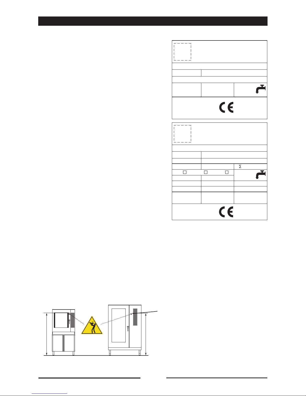
1.8 •Example of a data plate:
1.9 •The positions of the inlet and drain
connections are clearly labelled. For further
details,seetheinstallationdiagramattached
to this manual.
1.10 •Intheeventofbreakdownorfaultyoperation,
switchofftheovenimmediately!
1.11 •During installation and/or maintenance work it
is recommended you wear gloves to protect
your hands.
1.12 •Safety sticker
•Maximum height for inserting containers with
liquids.
ATTENTION:toavoidscalding,donotuse
thecontainersfilledwithliquidorfoodwhich,
throughcookingbecomefluid,atlevels
higher than those which can be observed.
1•GENERALREMINDERS
90027360rev00
0085
2008
EN 203/A1 AC 230V 50Hz
IT
IPX 5
G 25 / m3/h
Qn 40 kW
Cat.
II 2H3+
NR XXXXXXXXXX
kPa
200 - 500
P mbar
20; 28-30/37
TOT 1 kW1 x 0.55 kW
G 20 / m3/h
G 30 3.16 Kg/h
Pmax / mbar Pmax / mbar
Pmin / mbar Pmin / mbar Pmin / mbar
A3 B13 B23
2008
3N AC 400V 50Hz
IPX 5
NR XXXXXXXXXX
kPa
200 - 500
TOT 8 kW1 x 0.25 kW
TYP. XXXXXXXX
TYP. XXXXXXXX
LOGO
LOGO
1600 mm (63 inch)
2•TECHNICALDATA
4
90027360rev00
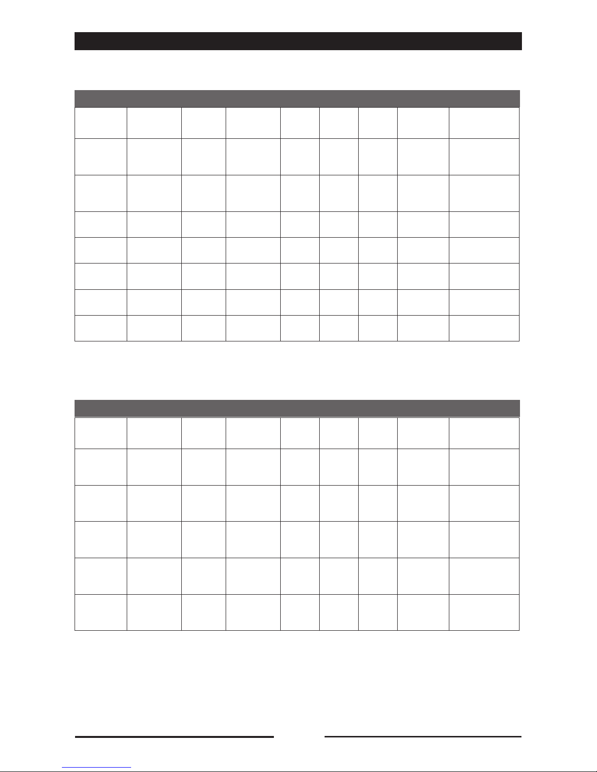
TABLE 1: GENERAL DATA - ELECTRIC OVENS
MODELS KME .... - KVE .... - GEM .... - GEV....
MODELS CVE .... - CEV ....
Model Supply
voltage Frequency Total power
imput Amps Chamber
power
Boiler
power Motor
Oil-proof connection
cable ( * )
6 x GN 1/1
3N AC 400 V
3 AC 230 V
AC 230 V
50 Hz 8,25 kW
12
20
36
8 kW 6 kW 1 x 0,2 kW
5 x 1,5 mm2
4 x 2,5 mm2
3 x 6 mm2
7 x GN 1/1
8 x GN 1/1
3N AC 400 V
3 AC 230 V
AC 230 V
50 Hz 10,5 kW
15
25
46
10 kW 7,5 kW 1 x 0,37 kW
5 x 1,5 mm2
4 x 2,5 mm2
3 x 10 mm2
10 x GN 1/1 3N AC 400 V
3 AC 230 V 50 Hz 16 kW 23
40 15 kW 15 kW 1 x 0,55 kW 5 x 2,5 mm2
4 x 6 mm2
7 x GN 2/1 3N AC 400 V
3 AC 230 V 50 Hz 19 kW 31
53 18 kW 15 kW 1 x 0,55 kW 5 x 4 mm2
4 x 10 mm2
10 x GN 2/1 3N AC 400 V
3 AC 230 V 50 Hz 31 kW 45
78 30 kW 30 kW 1 x 0,55 kW 5 x 10 mm2
4 x 25 mm2
20 x GN 1/1 3N AC 400 V
3 AC 230 V 50 Hz 31,8 kW 46
80 30 kW 30 kW 2 x 0,55 kW 5 x 10 mm2
4 x 25 mm2
20 x GN 2/1 3N AC 400 V
3 AC 230 V 50 Hz 61,8 kW 89
155 60 kW 60 kW 2 x 0,55 kW 5 x 25 mm2
2x (4 x 25 mm2)
Caution: The residual current device to be installed between the mains and the appliance
must be sized for a leakage of 1 mA x kW of power installed.
Model Supply
voltage Frequency Total power
imput Amps Chamber
power
Boiler
power Motor
Oil-proof connection
cable ( * )
4 x GN 2/3
3N AC 400 V
3 AC 230 V
AC 230 V
50 Hz 3,4 kW
5
8
14
3,15 kW - 1 x 0,2 kW
5 x 1 mm2
4 x 1 mm2
3 x 1,5 mm2
5 x GN 1/1
3N AC 400 V
3 AC 230 V
AC 230 V
50 Hz 6,25 kW
10
18
32
6 kW - 1 x 0,2 kW
5 x 1,5 mm2
4 x 2,5 mm2
3 x 4 mm2
6 x GN 2/3
3N AC 400 V
3 AC 230 V
AC 230 V
50 Hz 5,25 kW
8
13
23
5 kW - 1 x 0,2 kW
5 x 1 mm2
4 x 1,5 mm2
3 x 4 mm2
6 x GN 1/1
3N AC 400 V
3 AC 230 V
AC 230 V
50 Hz 7,75 kW
11
19
34
7,5 kW - 1 x 0,2 kW
5 x 1,5 mm2
4 x 2,5 mm2
3 x 6 mm2
10 x GN 1/1 3N AC 400 V
3 AC 230 V 50 Hz 15,5 kW 22
39 15 kW - 2 x 0,2 kW 5 x 2,5 mm2
4 x 6 mm2
Caution: The residual current device to be installed between the mains and the appliance
must be sized for a leakage of 1 mA x kW of power installed.
( * ) Flexible cable underneath sheath resistant to oil with designation 60245-IEC-57

5
2•TECHNICALDATA
90027360rev00
TABLE 2: GENERAL DATA GAS OVENS
Model Supply
voltage Frequency Imput Motor
Oil-proof
connection cable
( * )
Gas power
w/boiler
Gas power
w/o boiler
Gas
connection
5 x GN 1/1
6 x GN 1/1 AC 230 V 50 Hz 0,25 kW 1 x 0,2 kW 3 x 1 mm2- 8,5 kW 1 x R 1/2”
7 x GN 1/1
8 x GN 1/1 AC 230 V 50 Hz 0,5 kW 1 x 0,37 kW 3 x 1 mm215 kW 12 kW 1 x R 1/2”
10 x GN 1/1 AC 230 V 50 Hz 1 kW 1 x 0,55 kW 3 x 1 mm228 kW 18 kW 1 x R 1/2”
7 x GN 2/1 AC 230 V 50 Hz 1 kW 1 x 0,55 kW 3 x 1 mm230 kW 20 kW 1 x R 1/2”
10 x GN 2/1 AC 230 V 50 Hz 1 kW 1 x 0,55 kW 3 x 1 mm240 kW 27 kW 1 x R 1/2”
20 x GN 1/1 AC 230 V 50 Hz 1,8 kW 2 x 0,55 kW 3 x 1,5 mm248 kW 36 kW 1 x R 3/4”
20 x GN 2/1 AC 230 V 50 Hz 1,8 kW 2 x 0,55 kW 3 x 1,5 mm280 kW 54 kW 1 x R 3/4”
Caution: The residual current device to be installed between the mains and the appliance
must be sized for a leakage of 1 mA x kW of power installed.
( * ) Flexible cable underneath sheath resistant to oil with designation 60245-IEC-57

6
2•TECHNICALDATA
90027360rev00
TABLE 3: GENERAL WATER DATA
TABLE 4: FLUE GAS EXTRACTION DATA (TYPE B13)
(1) The ovens are equipped with two water inlets, one for non-softened cold water and the other for hot water (max. 50 C) or softened cold water.
WITH STEAM GENERATOR
Model
Water
pressure
kPa
Softened
water
consumption
max. l/h
Water
connection
ELECTRIC
6 x GN 1/1 200 - 500 7 2 x R 3/4 (1)
7 x GN 1/1
8 x GN 1/1 200 - 500 10 2 x R 3/4 (1)
7 x GN 2/1
10 x GN 1/1 200 - 500 19 2 x R 3/4 (1)
10 x GN 2/1 200 - 500 30 2 x R 3/4 (1)
20 x GN 1/1 200 - 500 37 2 x R 3/4 (1)
20 x GN 2/1 200 - 500 68 2 x R 3/4 (1)
GAS
7 x GN 1/1
8 x GN 1/1 200 - 500 8 2 x R 3/4 (1)
7 x GN 2/1
10 x GN 1/1 200 - 500 17 2 x R 3/4 (1)
10 x GN 2/1 200 - 500 24 2 x R 3/4 (1)
20 x GN 1/1 200 - 500 24 2 x R 3/4 (1)
20 x GN 2/1 200 - 500 48 2 x R 3/4 (1)
WITHOUT STEAM GENERATOR
Model
Water
pressure
kPa
Softened
water
consumption
max. l/h
Water
connection
ELECTRIC
4 x GN 2/3 200 - 500 4 2 x R 3/4 (1)
6 x GN 2/3 200 - 500 8 2 x R 3/4 (1)
5 x GN 1/1
6 x GN 1/1 200 - 500 8 2 x R 3/4 (1)
2x
5 x GN 1/1 200 - 500 8 + 8 2 x R 3/4 (1)
7 x GN 1/1
8 x GN 1/1 200 - 500 8 2 x R 3/4 (1)
7 x GN 2/1
10 x GN 1/1 200 - 500 15 2 x R 3/4 (1)
10 x GN 2/1 200 - 500 15 2 x R 3/4 (1)
20 x GN 1/1 200 - 500 30 2 x R 3/4 (1)
20 x GN 2/1 200 - 500 30 2 x R 3/4 (1)
GAS
5 x GN 1/1
6 x GN 1/1 200 - 500 8 2 x R 3/4 (1)
7 x GN 1/1
8 x GN 1/1 200 - 500 15 2 x R 3/4 (1)
7 x GN 2/1
10 x GN 1/1 200 - 500 22 2 x R 3/4 (1)
10 x GN 2/1 200 - 500 22 2 x R 3/4 (1)
20 x GN 1/1 200 - 500 30 2 x R 3/4 (1)
20 x GN 2/1 200 - 500 44 2 x R 3/4 (1)
Models 7 x GN 1/1
8 x GN 1/1 10 x GN 1/1 10 x GN 2/1 20 x GN 1/1 20 x GN 2/1
Flue liner
pressure - 0,9 Pa - 1,8 Pa - 2,7 Pa - 2,2 Pa -
Volumetric
mass 18,6 g/sec. 28,4 g/sec. 34,5 g/sec. 39,9 g/sec. -
Flue gas
Temperature 145 °C 190 °C 250 °C 210 °C -

7
3.1 •The room where the oven is to be fitted has
to be well ventilated with all the openings
required for rooms with gas installations
(see specific regulations).
3.2 •In addition, it is good policy to locate the
appliance under an extractor hood so that
cooking vapours can be removed rapidly
and continuously.
3.3 •The room must have a flue gas extraction
stack (appliances with installation type
B13), or a suitable flue gas extraction
system fitted with all relevant safety
devices (appliances with installation type
B23). Further details are given under the
heading: “Gas connection procedures”.
Check with the appropriate agency whether
or not special authorization is required
for the emission of flue gases into the
atmosphere.
3.4 •Current CEI (Italian Electrotechnical
Committee) regulations require the
installation of a multiple pole switch
between the oven and the electrical power
supply; the switch must have a contact
gap of at least 3 mm on each pole.
3.5 •The oven needs two water supplies, one
of which need not be softened, but must
necessarily be cold (for condensing steam).
The other supply, serving the vaporizer,
must incorporate a softener with suitable
flow and pressure specifications (see
technical data and water connections
heading). A shutoff valve must be installed
on each of the water supply pipelines to
the appliance.
3.6 •The room must have a water drain in a
goodposition forthe ovento beinstalled,
its specifications are given under the
heading “Water and drain connections” in
this manual.
3.7 •The gas supply plumbing must be installed
in accordance with current regulations,
adopting pipe sections and pressures
suitable for the appliance (see technical
data and gas connections heading).
A fast acting shutoff valve must be installed
on the gas inlet line to the appliance. It is
absolutely essential that this valve should
be specified to current standards and type
test approved.
3.8 •The electrical isolating switch and the
water and gas shutoff valves must all be
located near to the appliance, within easy
reach for the user.
3•SPECIALREQUIREMENTSFORTHEINSTALLATIONSITE
90027360rev00

8
Throughout installation it is vital to observe
the following requirements:
4.1 •any health and hygiene standards
applicable to kitchens and eating places;
4.2 •local and/or territorial building regulations
and fire prevention standards;
4.3 •current accident prevention guidelines;
4.4 •CEI requirements relating to electrical
systems;
4.5 •UNI-CIG 8723 Standard “Gas systems for
appliances used in professional kitchens
andcommunalfacilities”;
4.5 •the regulations of the gas supply company
or agency;
4.7 •the regulations of the electrical power
supply company or agency;
4.8 •any other local regulations.
4•STATUTORYREQUIREMENTS,TECHNICALREGULATIONSANDDIRECTIVES
90027360rev00
5.1 •Topositiontheappliances,itisrecommended
to use the mount offered by the manufacturer;
shouldyouwanttodothingsdifferently,itis
necessary to take account of the weight of
the appliance.
5.2 •Before manoeuvring the oven into the
selectedposition,attachthewaterinlethoses
and waste pipe to the relative connection
points (refer to headings describing the water
and drain connections).
5.3 •The distances from other appliances or from
adjacent walls that must be left to allow
access for servicing operations will be found
on the installation diagram for the oven to
connect. In the event of the oven being
installeddirectlyagainstaninflammablewall,
suitable heat insulation must be provided.
Current fire regulations should be
meticulously observed and respected. Do not
obstruct the openings and slots in the casing
as they disperse the heat in the electric
component compartment.
Keep strictly to the installation diagrams.
5.4 •Oncetheapplianceisinstalled,theelectrical
power cable must be protected, and never
stretched or tugged.
5.5 •The appliance must be level: any difference
in level or sloping of the supporting surface
should be eliminated. Differences in level or
sloping negatively affect oven operation.
5•POSITIONING

9
90027360rev00
5•POSITIONING
5.6 •Removeallpackingmaterialsandpeelaway
the protective plastic film from all external
surfaces of the oven.
5.7 •
For free-standing models, the appliance needs
to be levelled: small differences in level of the
supporting surface can be eliminated with the
adjustable feet (by screwing or unscrewing
them). A significantly uneven or sloping stance
can affect the operation of the oven adversely.
For models equipped with a pan trolley,
it is necessary to pay special attention when
levelling.
5.8 •Liningupthepantrolleys20x1/1GNand
20x2/1GN.Ifthefloorisnotlevel,aremedy
must be found using an access rampwith a
maximum gradient of 4° (not included inthe
supply).
If there is an outlet grate in front of
theappliance,it isnecessary tofitrunners in
thepan trolley entry area.
OK
OK
201 - 202
X = 200 mm
Y = 300 mm
OK
OK

10
90027360rev00
6•ELECTRICALCONNECTIONSANDEQUIPOTENTIALBONDING
6.1 •
As this oven is a type X appliance (oven
without power cable and plug), the cable
and other hardware needed to make the
connection to the electrical power supply
must be provided by the installer. The cable
must satisfy the requirements indicated in
table 1 “General data”.Asalreadymentioned,
the oven must be connected to the power
supply by way of a multiple pole main isolating
switch ensuring a gap between open contacts
of at least 3 mm on each pole.
6.2 •
To gain access to the AC mains connection
terminal board, the right hand panel of the
casing must be removed by undoing the fixing
screws (all models).
6.3 •
The cable must be fed in from beneath the
clamp. The individual wires are then fastened
to the corresponding terminals of the terminal
board. The earth wire must be longer than the
otherwires,so that in theeventof the cable
being jerked or the clamp broken, the live
wires will disconnect first.
Check the efficiency of the isolating switch.
6.4 •
The oven must be kept in an equipotential
system. This connection is made by wiring a
conductor of nominal cross section 10 mm
2
to
the corresponding terminal at the back of the
oven,whichismarkedwiththeinternationally
recognized symbol.
All appliances in the room are bonded in this
way and connected to the earth system of the
building.
6.5 •
The electrical safety of this appliance can
be guaranteed only when it is connected
correctly to an efficient earth system, in
compliance with current standards.

11
90027360rev00
7.1 •As all ovens of the series are fitted with
an alternating fan motor (clockwise and
anticlockwise rotation), there is no need
for the fan to rotate in any particular
direction. Simply verify, when
commissioning the appliance, that
the fan is balanced and rotates freely.
Warning: the
20 x GN 1/1 and 20 x GN 2/1
models are equipped with two motors.
7.2 •When making the electrical connection
you need to take care that the neutral
pin of the terminal block corresponds to
the neutral wire of the supply line. If this
connection is not made correctly, the
burners will not be able to operate.
7.3 •This trouble is indicated:
On gasmodels mechanicalversion by the
burnerignitionresetbutton,whichislitup.
On gas models electronic version via the
electronic card.
7.4 •Check also that the neutral registers
zero potential when tested. If not, the
fault already described in point three of
this section will occur. In this eventuality,
consult the installer of the building’s
electrical system.
7•POINTSTOREMEMBERWHENMAKINGTHEELECTRICALCONNECTION

12
90027360rev00
8•WATERANDDRAINCONNECTIONS
8.1•WATERPRESSURE
The pressure of the water in the network
must be between 200 and 500 kPa,
as already stated under the heading
“Technical Data”. If the supply pressure is
higherthanthis,apressurereductionvalve
must be installed between the oven and
the main.
8.2• WATERCONNECTIONSTOTHE
BOILER (IF APPLICABLE) AND
VAPORIZER
The water supplied to the vaporizer must
be either cold and softened or hot (max
50 °C), as described below. The water
connection is R 3/4”. The hose for
connection to the water supply must be
provided by the installer. Do not re-use
pre-existing or already used connection
tubes. A shutoff valve must be installed on
the line between the oven and the supply.
8.3• WATERSPECIFICATIONS
The characteristics of the water must come
within the limits given below, in order to
preventbothcorrosion,whichisextremely
damaging for the appliance, due to
supplying water that is too softened or too
aggressive,andscalingin theovenandin
the water system in the case of supplying
water that is too hard.
Hardness: between6°and9°TH
PH: greaterthan7.5
Chlorides: lessthan30ppm
These values are important for ensuring that
the water used by the appliance is suitably
treated!
8.4•WATERCONNECTIONSFOR
CONDENSING STEAM
The water used for condensing steam need
not be softened, but must necessarily be
cold. The water connection is R 3/4”. The
hose for connection to the water supply
must be provided by the installer. Do
not re-use pre-existing or already used
connection tubes. A shutoff valve must be
installed on the line between the oven and
the supply.
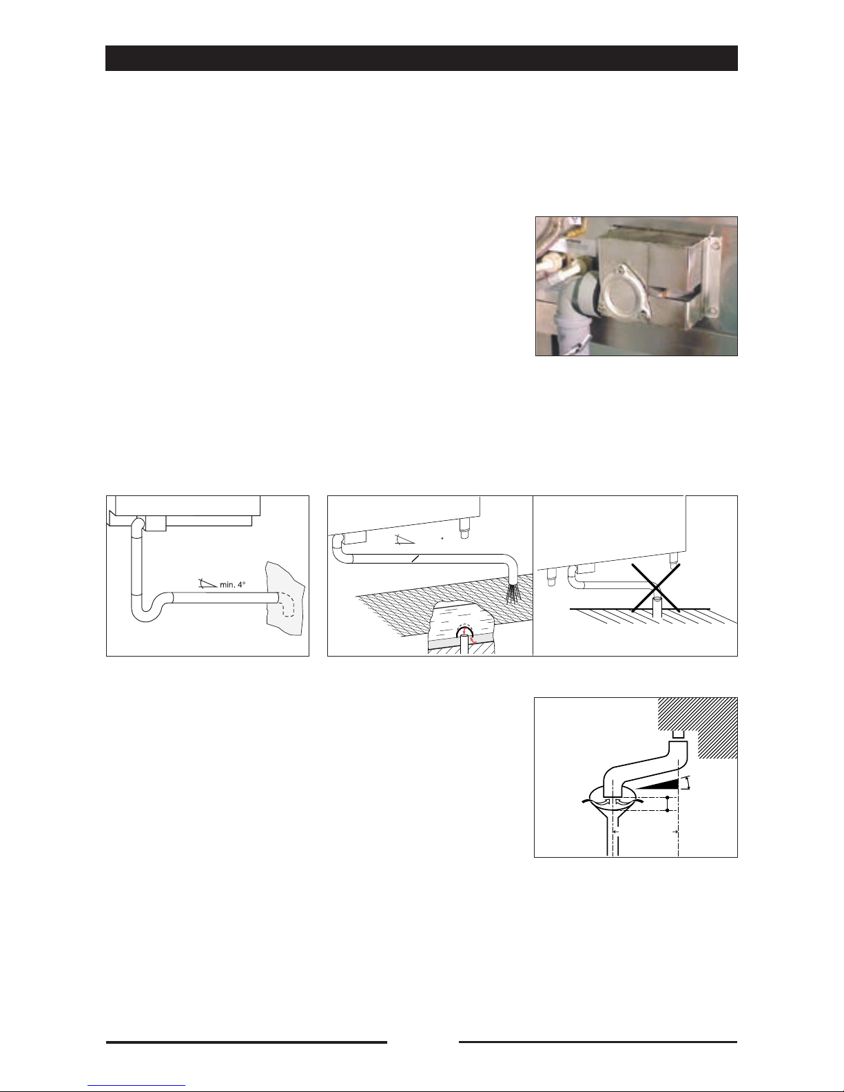
Fig.2 Fig.3
13
90027360rev00
8•WATERANDDRAINCONNECTIONS
Forthe range withthe drain asper fig.1 it is
possible to make a direct connection with an air
trap, without fitting a drain cup, as the drainage
manifoldsystemhasaninternalairdrop(Fig.2).
With a drain on the floor without an air trap it is
necessary to have an outlet clearance of 2 cm
(Fig.3).
For the remaining models it is imperative to
fit a drain cup to ensure a minimum air drop of
25 mm. between the appliance’s plastic drain
elbow and drain line. A direct connection is not
permissible.
8.5•DRAINING
The water is drained off by gravity through
a heat-resistant pipe DN 50 (not flexible),
maximumlength2m,installedatanangle
of no less than 4°.
Mean temperature of the drain water: 65 °C.
Fig.1
WARNING:
Thedrainlinemustbeoutsidetheperimeteroftheoven.
Itisprohibitedtoreducethedraindiameter.
Max. 200 cm
Min. 4
25 mm.
min. 4
O 50 mm / 1,9 inch

14
90027360rev00
9.1•THECALOUT
The CALOUTisacleaningsystem,which
keeps the steam generator free from
limescale and prevents the latter from
building up.
The CALOUT system is available AS
STANDARD for ovens equipped with
steam generator included in the HEART
range both Xand S versions.
The ovens equipped with CALOUT can be
directly connected to the water supply
withoutanyneedforawatersoftener,only
if water hardnessdoesnotexceed25°fH.
Forhardnessvaluesgreaterthan25°fH
itisrequiredtheinstallationof a water
softenerabletobringthembelow25°
fH.
Waterhardnessparameters
conversiontable
The CALOUT system efficiency is
guaranteed only if the anti-limescale and
non toxic“Calfree” product provided by
the producer is used.
WARNING: No other anti-limescale product
can be used to replace the“Calfree”
provided by the producer.
The CALOUT system allows for periodic
cleaning of the steam generator through
a specific program to be initiated by
the user when signalled by the oven
warning (see the oven user manual).
WARNING: FAILURE TO COMPLY
WITH THE CALOUT USAGE TIMES
MAY AFFECT THE OPERATION
AND INTEGRITY OF THE STEAM
GENERATOR (inthiscasethesteam
generatorrepairorreplacementwillnot
behonouredaswarranty).
9•CALOUT
°fH
(°tH)
°dH °eH
(Clark°)
ppm
(mg/lt)
gr/gal
(US)
1°fH
(°tH) 10,56 0,7 10 0,6
1°dH 1,79 11,25 17,9 1,07
1°eH
(Clark°) 1,43 0,8 114,28 0,86
1ppm
(mg/lt) 0,1 0,06 0,07 10,06
1gr/gal
(US) 1,71 0,96 1,2 17,15 1
15
90027360rev00
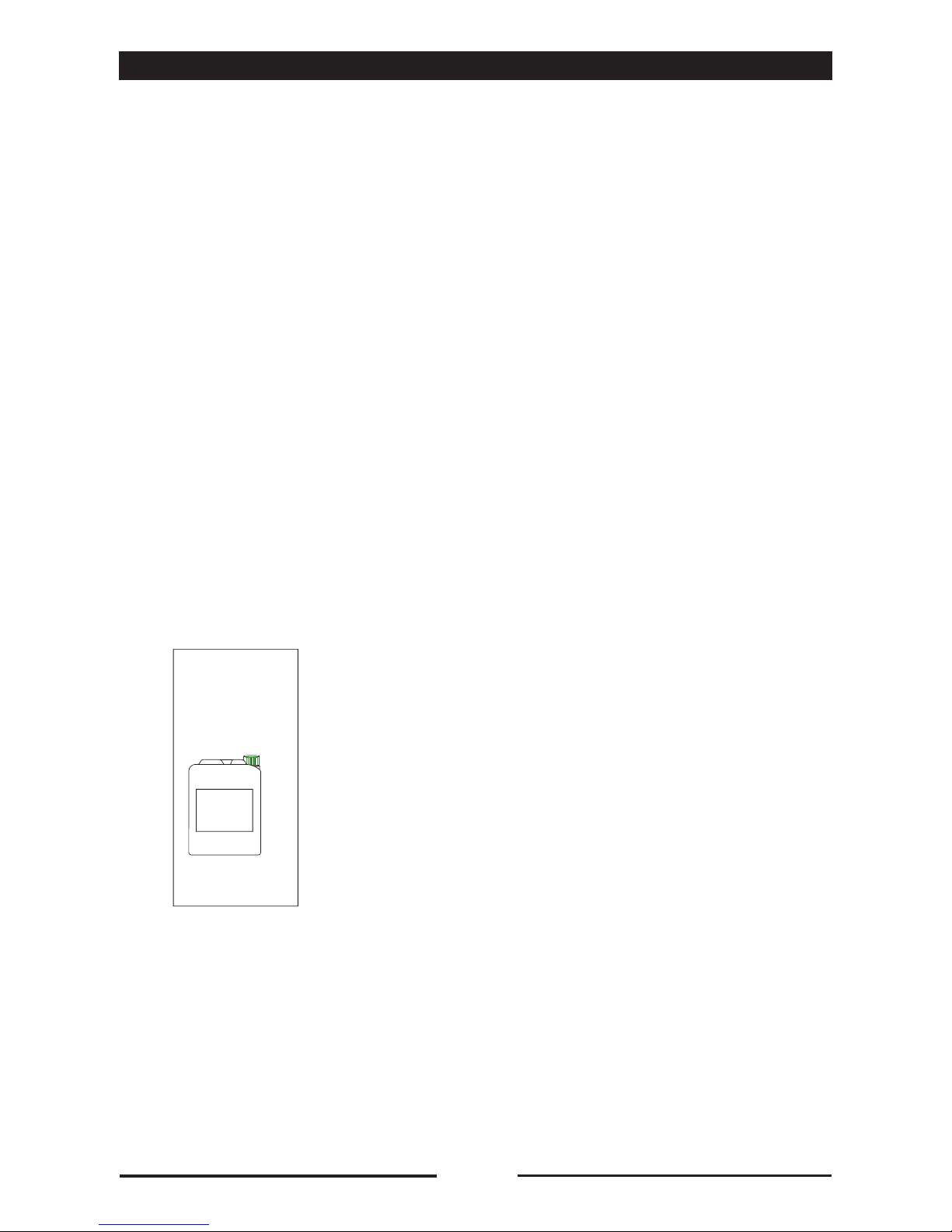
9.2•INSTALLINGOVENSWITHCALOUT
DEVICE
•Placethetankoftheanti-limescale
“Calfree” with the GREEN cap (supplied
with the oven) on the right side of the oven.
•InsertthelittlehosewiththeGREEN
cap that comes with the oven and is
marked with the CALOUT label(seethe
connectionontherightsideoftheoven)
until it touches the bottom of the tank and
close the cap tightly.
ONLYUSETHE“CF010-CALFREE”
PRODUCT SUPPLIED BY THE
PRODUCER.
NEVER USE GENERIC ANTI-LIMESCALE
OR DESCALING PRODUCTS.
USING ANY OTHER PRODUCTS
VOIDS THE WARRANTY ON CALOUT
SYSTEM COMPONENTS AND STEAM
GENERATOR.
IMPORTANT:
The manufacturer to avoid connection
errors and tank exchange or confusion has
provided the following features:
•Thecapofthetankcontainingtheanti-
limescale product “Calfree” for the oven
CALOUT system is GREEN coloured.
•Thecapofthetankcontainingthealkaline
detergent “Combiclean” (intended for the
washing system) for the oven is YELLOW
coloured.
Inanycase,thetankscontainingthe
anti-limescale“Calfree”andthe
“Combiclean”detergentaremarked
withlabelsbearingproductsname,
specificationsandinstructionsforuse.
9•CALOUT
CALFREE
Anti-limescale,non-
toxic product for the
prevention of limescale
deposits in the steam
generator tank
CF 010
10 lt.
CALFREE

11.1 • GAS CONNECTION
The section of the gas supply pipe must be
chosen according to the type of gas and
the consumption of the appliance to be
connected. The system must be designed
and installed in accordance with current
regulations. The gas connection on
the oven is R 1/2” or R 3/4”, and this
sectionmustneverbereduced.
A fast acting shutoff valve must be installed
on the gas inlet line to the oven. The valve
must be type test approved in accordance
with current regulations.
The connection to the gas main can be
permanent or detachable; if flexible metal
tube is used, this should be made of a
stainless and corrosion resistant material
(rubber hose is not recommended).
If when making the connection you use any
sealing materials, they must be type test
approved for this purpose.
11.2•LEAKTEST
All connections between the mains and
the appliance must be tested for leakage.
The recommended method is to use a
proprietaryleakdetectionspray;alternatively,
a non-corrosive foamy liquid of any general
description can simply be brushed onto
the fittings: whichever method is used, no
bubbles should appear.
Never under any circumstances test for
gasleakswithanakedflame!
11.3•EXHAUSTINGFLUEGASES
Modelwith5,6and7pansGN1/1
Since this appliance due to its capacity has
installation type A3, it is not necessary to
connect it to a stack for extracting the flue
gases. The flue gases can be exhausted into
the installation room. It is especially important
tohavegood,continuousventilation!
Remainingmodels
As these ovens have a power rating of
>14 kW, type B installation is required. The
installer must select one of the methods
described below, according to the design
of the building and of the room where the
appliance is sited. The diameter of the flue
pipes must be as indicated in the installation
diagrams.
Warning:
fluegasesmayreachtemperaturesof400
°C!
Fumesmustneverbeductedawayutilizing
anextractionsystem!
Clear the gas supply system of any
machining debris before connecting the
oven!
11•GASCONNECTIONPROCEDURES
16
90027360rev00
10.1 •Under no circumstances must vents A
and B be shut, blocked or ducted into
otherpipes.
A - Vent to extract vapours from the oven
B - Safety vent
10•VENTS
AB

17
90027360rev00
11•GASCONNECTIONPROCEDURES
Afterinstallation,theinstallermustupdatethedataplatebytickingthebox,correspondingtothe
typeofinstallationmade,withanindeliblemarkerpen.
The manufacturer accepts no liability for any damage or malfunctioning of the appliance
attributable to the absence or inadequacy of earthing systems, to the incorrect arrangement or
installation of auxiliary systems, also to incorrectly made connections or to non-compliance of
thebuilding’selectricalsystemwithcurrentregulations.
InstallationtypeB23
Flue gases are exhausted mechanically through a
suction hood with a heat-resistant filter or a ducted
ceiling, without a damper being fitted, and
eitherconveyed into a stack or released directly to
the atmosphere together with other fumes extracted
from the room. Leave a suitable distance between
the oven’s smoke outlet and the hood filter or the top
intake.
Where extraction systems are selected for type
B23installations,thesemustbeproperlysizedand
specified with at least one interlock device that will
shut off the gas supply to the oven automatically
in the event of the extractor system failing to
operate.
InstallationtypeB13
Extraction with natural draught fitted with a
damper and a heat-resistant pipe (see “Flue
gas temperatures” in Table 4 under the heading
“Technical Data”) connected to the stack. Selecting
this type of installation the oven must be fitted with
a damper that is specific for each oven (as shown in
the drawing). If the oven is equipped with an adaptor
collarforstandardsizefluepipes,fittheadaptor.
Never under any circumstances must flue gases be
ducted away directly utilizing a mechanical extraction
system.
Stack connection
pipe
Adaptor
Damper
Hood filter
Suction hood
Ducted
ceiling

18
12.1 •All appliances, during final testing in the
factory, are fitted for the type of gas shown
on the sticker next to the data plate. Should
the appliance fitting not correspond to the
family of gases available on location, the
appliance must be converted to adapt to
the type of gas available. If conversion is
necessary, then you must inform Customer
Service and refer to the technical manual.
12.2 •Commissioning of the appliance to operate
at the rated heat output is dependent on the
inlet pressure and calorific value of the gas
and the correct amount of primary air.
12.3• The inlet pressure required for the appliance
to operate with the various types of gas
typically available will be within the limits
indicated in table 6 of the “Tecnical gas data”
booklet.
Theappliancemust notbecommissioned
if inlet pressure values are outside these
limits. If pressures differ from those indicated
in Table 6, the gas supply company or
agency should be contacted, or alternatively
the contractor by which the system was
installed in the building.
12.4•The lower calorific value of the gas can be
checkedwiththesupplycompanyoragency,
and should comply with the information given
in table 5 of the “Tecnical gas data” booklet.
12.5•MEASURINGTHEINLETPRESSURE
The inlet pressure is measured using a
manometer connected to the pressure tap (3)
of the gas adjustment valve. To gain access
tothevalve,theright-handsidecasingpanel
has to be removed.
Before connecting the manometer it is
necessary to loosen the screw sealing the
pressure tap (3). You then measure the
pressure with the burner in operation. The
value shown on the manometer must come
within the limits given in table 6 “of the
“Tecnical gas data” booklet.
Afterchecking,carefullyclosethescrew(3).
The sealed screws you can see on the valves
must never be tampered with under any
circumstances.
Tampering immediately invalidates
warranty!
12•OPERATINGATTHERATEDHEATOUTPUT
90027360rev00
Warning!
Thegassystemcomponentsarefittedforamaximumpressureof
65mbar.Higherworkingpressuresarenotpermissible.

12•OPERATINGATTHERATEDHEATOUTPUT
CHECKING NOMINAL HEAT CAPACITY
M VERSION
-ChamberBurner
Check the depth of the screw “A” in
accordance with table 5
of the “Tecnical gas
data” booklet,
using a gauge.
Shift the J3 jumper in TEST position - see
picture
Checkthattheburnerfanspeed,corresponds
to the data given in table 5 of the “Technical
gasdata”booklet.
Set 180 °C convection cooking at low speed
(whereapplicable),otherwiseatnormalspeed.
Checkthespeedatposition“IGN”,withtheJ3
jumper in TEST position.
After testing, shift the J3 jumper in the initial
NORM position.
Check the speed on position “MIN”.
Set the normal speed and check the speed at
position “MAX”.
Check the combustion, CO (ppm) and CO2
(%)values,withanappropriateinstrument:
Start the oven working, 180 °C convection
mode, open the door and activate the micro-
door with a magnet fixed with tape, the oven
restarts and wait for approximately 5 minutes.
Position the flue gas collection probe in the
flue gas outlet pipe (chamber and boiler).
The CO2must be for:
Naturalgas between9%and10.5%
L.P.G. between9%and13%
The CO must be no greater than 300 ppm
(measured).
Carry out the test in both convection and
steam mode.
If these readings are outside the ranges,
proceed as stated in the technical manual.
For the conversion from natural gas to LPG,
or vice versa, proceed as described in the
technical manual.
Readingin:
D-E=Hz(0-200Hz)
D-F=VDC (0-6 VDC)
-BoilerBurner
Repeattheseoperations,setting100°Csteam
cooking.
19
90027360rev00
Conversion:Asmentionedabove,everyapplianceisfactorysettoburnthetypeofgasspecified,
itmaybecomenecessarynonethelesstoconverttheappliancefromonetypeofgastoanother.
Therefore,onlypersonnelauthorizedbythecompanyandbelongingtothetechnicalservicewho
havethecorrespondingtechnicalhandbookcandothiswork.
A
3
MAX
IGN
MIN
J3
EFD

20
90027360rev00
CHECKING NOMINAL HEAT CAPACITY
S VERSION
- ChamberBurner
Check the depth of the screw “A” in
accordance with table 5
of the “Tecnical gas
data” booklet,
using a gauge.
Checkthattheburnerfanspeed,corresponds
to the data given in table5ofthe“Technical
gasdata”booklet.
To enter the management screen of the burner to
check:
Withtheapplianceliveanddisplayoff,press
button 1, thedisplay2shows [USb], turnknob3
until [rEL]isdisplayed,presstheknobtoconfirm
the selection
Turn knob 3to set the password for parameter
modification and confirm by pressing knob 3.
12•OPERATINGATTHERATEDHEATOUTPUT
1
2
3
5
4
A
3
This manual suits for next models
12
Table of contents


