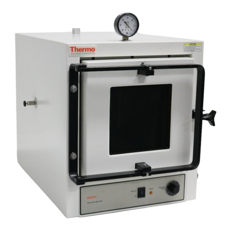
Thermo Scientific PRECISION 6502 Manual

Installation/Service Manual
PRECISION Vacuum Oven
Model 6502/6503 (29)
Thermo Scientific
401 Millcreek Road, Box 649
Marietta, Ohio 45750
USA
Phone: 740-373-4763
Toll Free: 800-848-3080
FAX: 740-373-4189
Manual P/N 3177884
Rev. E Dated 09SEP09
OVEN
Off
On

NOTICE
THE MATERIAL IN THIS MANUAL IS FOR INFORMATION PURPOSES ONLY. THE
CONTENTS AND THE PRODUCT IT DESCRIBES ARE SUBJECT TO CHANGE WITHOUT
NOTICE. THERMO SCIENTIFIC MAKES NO REPRESENTATIONS OR WARRANTIES WITH
RESPECT TO THIS MANUAL. IN NO EVENT SHALL THERMO BE LIABLE FOR ANY
DAMAGES, DIRECT OR INCIDENTAL, ARISING OUT OF OR RELATED TO THE USE OF THIS
MANUAL.
For repair information or replacement parts assistance from the manufacturer,
call Technical Services using our toll free telephone number.
888-213-1790
(FAX)740-373-4189

Update parts list for new kit #'s
manual#, manufacture location
updated elec specs to UL report
Corrected 3174760 sw to 3175318
A
INDEX DATE AMENDED PAGES NOTES
REVISION STATUS
6/99
B
C
D
E
9/99
4/05
6/06
9/09
Initial release
11
36100119 (34001778)
ECR 23496
ECR25769/OV-321

Contents
Introduction ........................................................................................................................ 1
Unpacking and Damage..................................................................................................... 1
Installation and Adjustment .............................................................................................. 2
Specifications ..................................................................................................................... 2
Explanation of Controls ..................................................................................................... 3
Temperature Adjustment ................................................................................................... 4
Vacuum Operation ............................................................................................................. 4
Periodic Maintenance ........................................................................................................ 5
Door Gasket Compatibility (Chart)................................................................................... 6
Maintenance of Stainless Steel ......................................................................................... 7
Replacement Parts List.................................................................................................... 11
Wiring Diagrams ............................................................................................................... 12
Warranty ............................................................................................................................ 14


1
INTRODUCTION
Your satisfaction and safety are important to
Thermo and a complete understanding of this unit
is necessary to attain these objectives.
As the user of this apparatus, you have the
responsibility to understand the proper function
and operational characteristics of your oven. This
instruction manual should be thoroughly read and
all operators given adequate training before
attempting to place this unit in service. Awareness
of the stated cautions and warnings, and
compliance with recommended operating
parameters -- together with maintenance
requirements -- are important for safe and
satisfactory operation. The unit should be used
for its intended application; alterations or
modifications will VOID THE WARRANTY.
WARNING
AS A ROUTINE LABORATORY PRECAUTION,
ALWAYS WEAR SAFETY GLASSES WHEN
WORKING WITH THIS APPARATUS.
This product is not intended, nor can it be used,
as a sterile or patient connected device. In
addition, this apparatus is not designed for use in
Class I, II or III locations as defined by the National
Electrical Code.
UNPACKING AND DAMAGE
Save all packing material until unit is put into
service. This merchandise was carefully packed
and thoroughly inspected before leaving our
factory.
Responsibility for safe delivery was assumed by
the carrier upon acceptance of the shipment;
therefore, claims for loss or damage sustained in
transit must be made upon the carrier by the
recipient as follows:
1. Visible Loss or Damage: Note any external
evidence of loss or damage on the freight bill,
or express receipt, and have it signed by the
carrier's agent. Failure to adequately describe
such external evidence of loss or damage may
result in the carrier's refusing to honor your
damage claim. The form required to file such
claim will be supplied by the carrier.
2. Concealed Loss or Damage: Concealed
loss or damage means loss or damage which
does not become apparent until the
merchandise has been unpacked and
inspected. Should either occur, make a written
request for inspection by carrier's agent within
fifteen (15) days of the delivery date; then file
a claim with the carrier since the damage is
the carrier's responsibility.
If you follow the above instructions carefully, we
will guarantee our full support of your claim to be
compensated for loss or concealed damage.
DO NOT -- FOR ANY REASON -- RETURN THIS
UNIT WITHOUT FIRST OBTAINING
AUTHORIZATION. In any correspondence to
Thermo , please supply the nameplate data,
including catalog number and serial number.

2
Install Shelves
Two shelves are provided with the oven. Remove
the wrapped shelves from the chamber. Unwrap
the shelves and place in chamber. The two shelves
are adjustable up and down the chamber. If large
containers are to be placed in the oven, place one
shelf as close to the bottom of the chamber as
possible, but avoid direct contact with chamber
floor. Avoid placing items directly on chamber
floor. Insert the shelf clips into the shelf standards.
Place shelves in chamber with lip up.
NOTE
HEATERS ARE LOCATED ON BOTTOM OF
CHAMBER. PLACING AN ITEM DIRECTLY ON THE
CHAMBER FLOOR MAY CAUSE OVERHEATING OF
THE ITEM.
Install Thermometer
A thermometer well is located on top of the oven.
Place the supplied thermometer into the
thermometer well. THERMOMETER NORMALLY
FITS LOOSELY IN WELL.
INSTALLATION AND
ADJUSTMENT
NOTE
REFER TO THE PACKING CHECKLIST FOR THE
LIST OF ACCESSORIES SENT WITH THIS UNIT.
MAKE CERTAIN YOU HAVE ALL ACCESSORIES
BEFORE DESTROYING THE SHIPPING
CONTAINER AND PACKING MATERIAL.
Position Vacuum Oven
Place the oven on a bench or stand at a convenient
working height. Adjust the four (4) corner leveling
feet to level the oven.
CAUTION
MAINTAIN A MINIMUM OF 12 INCHES CLEARANCE
BETWEEN THE OVEN AND ANY COMBUSTIBLE
SURFACES.
SPECIFICATIONS MODEL
Catalog #
6502/6503 (29)
3166804, 3166805
Vacuum range Atmosphere to 30" Hg. with adequate pump
Temperature range 35°C to 200°C
Shelf capacity 1.25 sq. ft. (1161 sq. cm) per shelf
2 shelves standard
Inside dimensions, usable
Inches
Centimeters
(W-D-H)
12 x 19 x 12
30.5 x 48 x 30.5
Outside dimensions
Inches
Centimeters
(W-D-H)
19.75 x 27 x 22.5
50 x 69 x 57
Standard electrical service
Optional electrical service
1000 Watts, 120 VAC
50/60 Hz, 8.3 Amps
1000 Watts, 240 VAC
50/60 Hz, 4.2 Amps
Net weight
Pounds
Kilograms
116
53

3
Connect Power Cord
CAUTION
CHECK VOLTAGE AND WATTS STAMPED ON THE
DATA PLATE FOR COMPATIBILITY BEFORE
CONNECTING OVEN TO POWER SOURCE. THE
DATA PLATE CAN BE FOUND NEAR THE POWER
CORD. FIRST ENSURE THAT THE POWER SWITCH
IS IN THE "OFF" POSITION.
EXPLANATION OF CONTROLS
Control and Indicator Description
1. Power Switch - Applies power to the oven
heater controls.
2. Temp. Control - Regulates the oven
temperature.
3. Heating Indicator - Indicates when the oven
is being heated.
4. Thermometer Well - Located on Top rear of
Oven. Provides a means of monitoring the
chamber temperature through a glass column
thermometer.
5. Vacuum Gauge - Indicates chamber vacuum
(in inches of mercury).
6. Hose Connections - Used for connecting
minimum 1/4" vacuum tubing between oven
and vacuum pumping systems, or other
apparatus.
7. Valves - Used for evacuating chamber,
controlling vacuum, or for bleeding air and
other gasses into chamber.
8. Penetration Port - One (1) inch NPT port
projecting out back of oven for attachment to
a high capacity vacuum system for quick
evacuation of the chamber.
OVEN
Off
On
Temp.
Control
Heating
Indicator
Power
Switch
Valves
Penetration Port
(rear of oven)
Hose Connections
(Not Shown)
Vacuum
Gauge
Thermometer Well
(Not Shown)

4
TEMPERATURE
ADJUSTMENT
Apply power to the unit by pressing the power
switch to "On". Turn the Temp. Control knob fully
clockwise. The "Heating" indicator will glow when
the unit is heating. When the temperature reaches
the desired operating level (as indicated on the
thermometer) turn the Temp. Control knob
counterclockwise until the "Heating" indicator just
turns off. Allow the temperature to cycle on and off
several times (3 to 4 hours) to make sure the oven
has stabilized. Adjust the Temp. Control knob up
or down as necessary.
Oven thermostats are set for operation at
temperatures over 100°C.
For control at lower temperatures, readjustment
of the thermostat may be necessary.
Two allen wrenches are required:
• 1/16" for the thermostat shaft
• 5/64" for the thermostat knob
1. Bring oven to room ambient.
2. Energize oven.
3. Set thermostat fully counter-clockwise (heat
lamp is on).
4. Remove thermostat knob. Note small allen
screw within shaft.
5. Turn shaft allen screw clockwise until lamp
goes out.
6. Attempt to control at the desired temperature.
7. It may be necessary to repeat this procedure.
NOTE
WHEN THE OVEN IS NEW AND IS FIRST HEATED,
THE INSULATION WILL BECOME SCORCHED AND
SOME SMOKE AND BURNING ODOR WILL OCCUR.
IT IS NORMAL FOR THIS CONDITION TO LAST 2
TO 3 HOURS AT HIGH HEAT.
VACUUM OPERATION
The following information serves as a guide to
operation of the vacuum system.
The total variable leak rate of the oven is 3 inches
of mercury per cubic foot per 24 hours at 29 to 26
inches of mercury.
Vacuum Sealing Agents
High vacuum silicone grease is often necessary
to provide a proper seal at tubing connections,
valve connections, door seals, etc. This is
especially important at high vacuums. However,
there are restrictions to using silicone grease,
depending upon the type of materials placed in
the oven. Refer to the maintenance section of this
manual for restrictions.
Out Gassing
The operation of the oven at high temperature while
evacuating the chamber will help drive off absorbed
gasses on the walls and other surfaces and
facilitate attainment of high vacuums.
Evacuating Chamber
Connect vacuum tubing to either hose connection
on top of vacuum oven. Turn on the vacuum pump,
then open the valve on the oven. The vacuum
gauge will indicate when the desired pressure level
is obtained. Once obtained, close the valve, and
turn off the vacuum pump. Air may be bled into
the chamber through the unused valve to raise the
pressure level.
NOTE
TO MAINTAIN AS LEAK PROOF A SYSTEM AS
POSSIBLE USE ONLY VACUUM PUMP TUBING.
MAKE SURE ALL CONNECTIONS ARE TIGHT. USE
A VACUUM PUMP SIZED TO ADEQUATELY
EVACUATE THE OVEN VOLUME.
CAUTION
VACUUM PUMPS SHOULD NEVER BE TURNED
OFF WHILE CONNECTED TO A SYSTEM UNDER
VACUUM. OIL BACK UP INTO THE LINES AND
SYSTEM WILL OCCUR NECESSITATING
EXTENSIVE CLEAN UP.
When turning vacuum pump off, immediately
undo the connection at the oven valve or the
pump intake.
1. Close the vacuum valve
2. Turn the pump off.
3. Immediately break the connection at the pump
or oven.
4. Leave connection open for one minute, then
reattach.

5
PERIODIC MAINTENANCE
1. If the oven fails to maintain set temperature, it
may indicate a problem with the Temp.
Control, or possibly a heating element failure.
Contact our technical service representative.
2. Sometimes due to shipping, handling and
normal operational wear, oven doors will get
out of alignment. Realignment is
accomplished quickly and easily as follows:
a. Loosen the set screws holding the hinge
bar in place. (Note that the hinge bar moves
easily once the set screws are loosened.)
b. Center the door in the door frame and apply
pressure toward the top of the oven.
Retighten the set screws.
If properly aligned, the door frame should seat
freely against the door gasket without binding when
the oven is placed in the proper position. In case
the latch bar on the right side of the oven is out of
alignment, it can be adjusted in the same manner.
3. Gaskets should be checked periodically for
hardening, shrinking, deterioration or other
signs of wear. It is advisable to keep several
gaskets available for use as replacement.
4. The oven is equipped with silicone door
gaskets, unless specified otherwise. Do not
use silicone door gaskets or vacuum grease
when evaporating solvents in the oven or
when using high analine point oils. BUNA-N
gaskets should be used in applications when
evaporation solvents or when using high
analine point oils.
5. The interior finish or silicone gaskets may be
damaged by the following:
Diesel oil
JP-4 oil
MIL-0-5606
Hydraulic Fluids
Butyl Acetate
Carbon Tetrachloride
Ethylene Chloride
Gasoline
Kerosene
Xylene
Methyl Chloride
Stoddard Solvent
Toluene
Aromatic Chlorinated solvent
6. Refer to the following chart as a guide to what
type of door gasket material is best suited for
your needs.

6
DOOR GASKET MATERIAL COMPATIBILITY GUIDE
Nitrile (Buna N) Fluorocarbon (Viton) Silicone
General
Continuous High Temperature Limit 257°F, 125°C 437°F, 225°C 482°F, 250°C
Low Temperature Capacity -67°F, -55°C -40°F, -40°C -103°F, -75°C
Dynamic Service/Abrasion
Resistance Compression
EXCELLENT VERY GOOD POOR
Set Resistance VERY GOOD VERY GOOD EXCELLENT
Fluid Compatibility
Acid, Inorganic FAIR EXCELLENT GOOD
Acid, Organic GOOD GOOD EXCELLENT
Aging (Oxygen, Ozone, Weather) FAIR/POOR VERY GOOD EXCELLENT
Air FAIR VERY GOOD EXCELLENT
Alcohols VERY GOOD FAIR VERY GOOD
Aldehydes FAIR/POOR POOR GOOD
Alkalis FAIR/GOOD GOOD VERY GOOD
Amines POOR POOR GOOD
Animal Oils EXCELLENT VERY GOOD GOOD
Esters, Alkyl Phosphate (Skydrol) POOR POOR GOOD
Esters, Aryl Phosphate FAIR/POOR EXCELLENT GOOD
Esters, Silicate GOOD EXCELLENT POOR
Ethers POOR POOR POOR
Hydrocarbon Fuels, Aliphatic EXCELLENT EXCELLENT FAIR
Hydrocarbon Fuels, Aromatic GOOD EXCELLENT POOR
Hydrocarbon, Halogenated FAIR/POOR EXCELLENT POOR
Hydrocarbon Oils, High Aniline EXCELLENT EXCELLENT VERY GOOD
Hydrocarbon Oils, Low Aniline VERY GOOD EXCELLENT FAIR
Impermeability to Gasses GOOD VERY GOOD POOR
Ketones POOR POOR POOR
Silicone Oils EXCELLENT EXCELLENT GOOD
Vegetable Oils EXCELLENT EXCELLENT EXCELLENT
Water/Steam GOOD FAIR FAIR

7
MAINTENANCE OF
STAINLESS STEEL
WARNING
UNIT MUST BE DISCONNECTED FROM POWER
SOURCE PRIOR TO SERVICING. IT IS
RECOMMENDED THAT ALL SERVICE BE
PERFORMED BY QUALIFIED SERVICE
PERSONNEL.
CAUTION
ELECTROLYSIS CAN DAMAGE STAINLESS STEEL.
THIS CAN OCCUR IF AN OBJECT IS ALLOWED TO
REST DIRECTLY ON THE SURFACE, TRAPPING
MOISTURE THAT BECOMES OXYGEN STARVED
BUT IS SURROUNDED BY WATER CONTAINING
OXYGEN. THE RESULTING ELECTROLYTIC
ACTION WILL PIT OR CORRODE THE STAINLESS
STEEL.
Background
Stainless steel is an alloy of steel with chromium
and nickel which increase the metal's resistance to
rust and corrosion. However, if not properly cared
for it can rust and corrode. Exposure to air provides
the passivation for clean stainless steel. This expo-
sure produces a thin, durable chromium-oxide film
that forms rapidly on the alloy surface and gives
stainless steel its characteristic "stainless" quality.
Exposure of the surface to water or other oxidizing
environments also produces this passivating film.
However, if free oxygen is not available due to
scale or contamination buildup the metal surface
may become vulnerable to attack.
Maintaining a neutral pH and frequent cleaning
with detergent and water will give you years of
trouble free service. The following are some guide-
lines to consider.
Other Water Additives
Proper maintenance of the stainless steel chamber
will help assure many years of service.
It should be cleaned regularly with mild soapy water
and rinsed with distilled water. Always thoroughly
dry the chamber after cleaning.
IMPORTANT
IF IT IS NECESSARY TO USE THE FOLLOWING
CHEMICALS, LIMIT THE EXPOSURE TIME TO A
MAXIMUM OF FOUR HOURS. CLEAN SURFACES
IMMEDIATELY AFTER USE.
Citric Acid (Boiling) Mercury Salts
Potassium Permanganate Phenol
Potassium Thiocyanate Lysol
Stannous Chloride Tartaric Acid
Aluminum Chloride Barium Chloride
Chlorinated Lime Calcium Chloride
Dakin's Solution Ferrous Chloride
Sodium Hypochlorite
NEVER USE THE FOLLOWING
Aqua Regia Ferric Chloride
Iodine Sodium Azide
Sulfuric Acid
Cleaning
Spills of any chemical, especially those listed
above should be removed as soon as possible and
the stainless steel surface cleaned with mild soapy
water followed by copious rinse with clean water.
Do not use soap filled or metallic pads. Even
stainless steel pads are to be avoided as they may
destroy the passive film on the surface of the metal
and create crevices that may harbor contamination.
If stubborn stains persist use a plastic light duty
cleansing pad and rub gently in the direction of
the metal grain. If stains continue to persist use
one of the following methods.
WARNING
THE FOLLOWING CHEMICAL METHODS HAVE
PROVEN SUCCESSFUL BUT EXTREME CARE
MUST BE TAKEN WHEN HANDLING THESE
MATERIALS. ALWAYS WORK IN AN AREA WITH
ADEQUATE VENTILATION. USE THE
PRECAUTIONS OUTLINED IN THE MATERIAL
SAFETY DATA SHEET (MSDS) AND
MANUFACTURER'S INSTRUCTIONS FOR THE
PRODUCT YOU ARE WORKING WITH. FOLLOW
THE PERSONAL PROTECTION INDEX FOUND IN
THE HAZARDOUS MATERIALS IDENTIFICATION
SYSTEM (HMIS) SECTION OF THE MSDS.

8
The use and disposal of these chemicals may be
regulated by your local municipality. Consult the
regulations before disposing of these materials.
1. Bathroom tub and tile cleaners. Available at
supermarkets.
2. Any of a variety of "scale removers" available
at your local supermarket or
hardware store. Generally sold for cleaning
coffee makers, humidifiers and vaporizers.
3. Citric acid based cleaners. Contact your lab
supply dealer.
4. A 15 to 35% phosphoric acid solution.
Available form chemical supply dealers for
scale and rust removal. Allow solution to soak
the surface affected until rust and scale is
loosened. Immediately rinse with copious
amounts of clean water.
5. Oxalic Acid 2% to 5% in warm water. Swab
solution on surface allowing it to remain until
rust is loosened. Immediately flush with
copious amounts of clean water.
6. A mixture of 20% nitric acid and 1.5%
hydrofluoric acid (or hydrochloric acid). Swab
solution on surface allowing it to remain until
rust is loosened. Immediately flush with
copious amounts of clean water.
The above are ranked in order of mild to strong
cleaning agents. Items 5 and 6 should only be
used if severe rust and scale stains have
developed and cannot be removed by any other
method. In any case the chemical should be
allowed to do the cleaning with minimal scrubbing.
Always follow the manufacturer's instructions.
Chamber Disinfecting
Materials known to be effective in disinfecting are:
*Household Bleach
*Glutaraldehyde
*Alcohol
Consult with your staff chemist for advice on using
these chemicals.

9
MAINTENANCE OF STAINLESS STEEL (CONT.)
The following chart is provided as a guide to cleaning the interior surface of your vacuum oven.
EFFECTIVE METHODS FOR CLEANING STAINLESS STEEL
Cleaning Agent * Method of Application** Effect on Finish
Routine Cleaning Soap, or ammonia, or
detergent and water.
Sponge with cloth, then rinse
with clear water and wipe dry.
Satisfactory for use on all
finishes.
Smears and Fingerprints Arcal 20, Lac-O-Nu, Lumin
Wash, O'Cedar Cream
Polish, Stainless Shine, or
Wind-O-Shine.
Rub with cloth as directed on
the package.
Satisfactory for use on all
finishes. Provides barrier
film to minimize prints.
Stubborn spots and
stains, baked-on splatter,
and other light
discolorations
Allchem Concentrated
Cleaner or Lusteel.
Apply with damp sponge or
cloth.
Satisfactory for use on all
finishes.
Samae, or Cameo Copper
Cleaner.
Rub with damp cloth. Satisfactory for use on all
finishes if rubbing is light.
Cooper's Stainless Steel
Cleaner, or Revere Stainless
Steel Cleaner.
Rub with damp sponge or
cloth.
Use in direction of polish
lines on No. 4 (polished)
finish. Use light pressure on
No. 2 (mill) and Nos. 7 and 8
(polished) finishes.
Liquid NuSteel. Rub with dry cloth. Use small
amount of cleaner.
Use in direction of polish
lines on No. 4 (polished)
finish. May scratch No. 2
(mill) and Nos. 7 and 8
(polished ) finishes.
Paste NuSteel, DuBois
Temp, or Aerogroom.
Rub with dry cloth using a
small amount of cleaner.
Use in direction of polish
lines on No. 4 (polished)
finish. May scratch No. 2
(mill) and Nos. 7 and 8
(polished) finishes.
Household cleansers, such
as Old Dutch, Lighthouse,
Sunbrite, Wyandotte, Bab-O,
Gold Dust, Sapolio, Bon Ami,
Ajax, Comet, Off, or Stainless
Steel Super Shine.
Rub with a damp cloth. May
contain chlorine bleaches.
Rinse thoroughly after use.
Use in direction of polish
lines on No. 4 (polished)
finish. May scratch No. 2
(mill) and Nos. 7 and 8
(polished) finishes.
Grade F Italian pumice, Steel
Bright, Lumin Cleaner, Zud,
Restoro, Sta-Clean, or
Highlite.
Rub with a damp cloth. Use in direction of polish
lines on No. 4 (polished)
finish. May scratch No. 2
(mill) and Nos. 7 and 8
(polished) finishes.
Penny-Brite or Copper-Brite. Rub with a dry cloth using a
small amount of cleaner.
Use in direction of polish
lines on No. 4 (polished)
finish. May scratch No. 2
(mill) and Nos. 7 and 8
(polished) finishes.
BuBois Stainless Steel
Polish.
No rubbing - just spray lightly
on dry surface and wipe off.
Forms thin, hard satin-sheen
finish that resists grease
stains, water marks,
fingerprints, etc.

10
EFFECTIVE METHODS FOR CLEANING STAINLESS STEEL (cont.)
Cleaning Agent * Method of Application** Effect on Finish
Heat Tint or Heavy
Discoloration
Penny-Brite or Copper-Brite. Rub with dry cloth. Use in direction of polish
lines on No. 4 (polished)
finish. May scratch No. 2
(mill) and Nos. 7 and 8
(polished) finishes.
Paste NuSteel, DuBois
Te m p , Ta r ni t e , o r K e l o x.
Rub with dry cloth or stainless
steel wool.
Use in direction of polish
lines on No. 4 (polished)
finish. May scratch No. 2
(mill) and Nos. 7 and 8
(polished) finishes.
Revere Stainless Steel
Cleaner, Take-Off, or AC-60
Apply with damp sponge or
cloth.
Use in direction of polish
lines on No. 4 (polished)
finish. May scratch No. 2
(mill) and Nos. 7 and 8
(polished) finishes.
Allen Polish, Steel Bright,
Wyandotte, Bab-O, Zud,
Dubrite, or Prepare Dex.
Rub with a damp cloth. Use in direction of polish
lines on No. 4 (polished)
finish. May scratch No. 2
(mill) and Nos. 7 and 8
(polished) finishes.
Burnt-on Foods and
Grease, Fatty Acids,
Milkstone (where
swabbing or rubbing is
not practical)
Easy-Off, De-Grease-It, 4 to
6% hot solution of such
agents as trisodium
phosphate, or sodium
tripolyphosphate, or 5 to 15%
caustic soda solution.
Apply generous coating.
Allow to stand for 10-15
minutes. Rinse. repeated
application may be
necessary.
Excellent removal,
satisfactory for use on all
finishes.
Tenacious Deposits, Rusty
Discolorations, Industrial
Atmospheric Stains
Oakite No. 33, Dilac, Texo
12, Texo N.Y., Flash-Klenz,
Caddy Cleaner, Turco Scale
4368 or Permag 57.
Rub with dry cloth. Use small
amount of cleaner.
Use in direction of polish
lines on No. 4 (polished)
finish. May scratch No. 2
(mill) and Nos. 7 and 8
(polished ) finishes.
Hard Water Spots and
Scale
Vinegar. Swab or wipe with cloth.
Rinse with water and dry.
Satisfactory for all finishes.
5% oxalic acid, 5% sulfamic
acid, 5 to 10% phosphoric
acid, or Dilac, Oakite No. 33,
Te xo 1 2 , Te x o N . Y
Swab or soak with cloth. Let
stand 10-15 minutes. Always
follow with neutralizer rinse,
and dry.
Satisfactory for all finishes.
Effective on tenacious
deposits or where scale has
built up.
Grease and Oil Organic solvents such as
carbon tetrachloride,
trichlorethylene, acetone,
kerosene, gasoline, benzene,
alcohol, and chlorethane n.u.
Rub with cloth. Organic
solvents may be flammable
and/or toxic. OBSERVE ALL
PRECAUTIONS AGAINST
FIRE. Do not smoke while
vapors are present, and BE
SURE AREA IS WELL
VENTILATED.
Satisfactory for use on all
finishes.
SUGGESTIONS:
- Use the mildest cleaning procedure that will do the job
effectively.
- Rub in the direction of polish lines for maximum effectiveness
and to avoid marring the surface.
- Rinse thoroughly with fresh water after every cleaning
operation.
- Wipe dry to avoid water markes.
NOTE:
* Use of proprietary names is intended only to indicate a type
of cleaner, and does not constitute an endorsement, nor is
omission of any proprietary cleaner to imply its inadequacy. It
should be emphasized that all products should be used in
strict accordance with instructions on package.
** In all applications a stainless steel wool or sponge or fibrous
brush or pads are recommended. Avoid use of ordinary steel
wool or steel brushes for scouring stainless steel.

11
REPLACEMENT PARTS LIST
Model 6502/6503 (29) Vacuum Oven
Part No. Description
3175318 Power Switch, 120V/240V
3167242 Thermostat Kit, 120V
3167243 Thermostat Kit, 240V
3175265 Thermal Cut-out
3175996 Thermometer
3167214 Vacuum Valve Kit
3167232 Vacuum Gauge Kit
3166994 Heater Service Kit (All Voltages)
3166194 Shelf Kit
3167239 Shelf, Standard Kit
3174675 Door Gasket, Silicone
3173927 Door Gasket, Buna-N
3173605 Door Gasket, Viton
3167059 Door Assembly
3166984 Door Latch Assembly
3167255 Foot Leveler Kit (4)
3174674 Silicon Window Gasket
3173926 Buna-N Window Gasket
3174683 Viton Window Gasket
3174083 Cap Nut
3167234 Door Hanger Kit
3167246 Power Cord Kit, 120V
3167247 Power Cord Kit, 240V
WHEN ORDERING REPLACEMENT PARTS,
PLEASE SPECIFY THE MODEL NUMBER AND
SERIAL NUMBER OF YOUR UNIT, AND DATE
PURCHASED. THE MODEL AND SERIAL
NUMBERS CAN BE FOUND ON THE NAMEPLATE
WHICH IS LOCATED NEAR THE SERVICE CORD.

12
WIRING DIAGRAMS
120 VOLT WIRING DIAGRAM
1
BLACK
GREEN/YELLOW
WHITE TERMINAL
CUTOFF
NC BLACK
PILOT
LIGHT
REG
HEATERS
BLACK
POWER SWITCH
TAN 5
TAN
4 TAN COM
TAN REGULATING
THERMOSTAT
13
2
BLACK

13
240 VOLT WIRING DIAGRAM
2
3
BLACK
BLACK
GREEN/YELLOW
WHITE TERMINAL
CUTOFF
NC BLACK
PILOT
LIGHT
REG.
HEATERS
BLACK
POWER SWITCH
TAN 5
TAN
4 TAN COM
1 TAN
REGULATING
THERMOSTAT
13

14
THERMO FISHER SCIENTIFIC STANDARD PRODUCT WARRANTY
The Warranty Period starts two weeks from the date your equipment is shipped from our facility. This allows for shipping time
so the warranty will go into effect at approximately the same time your equipment is delivered. The warranty protection
extends to any subsequent owner during the first year warranty period.
During the first year, component parts proven to be non-conforming in materials or workmanship will be repaired or replaced
at Thermo's expense, labor included. Installation and calibration are not covered by this warranty agreement. The Technical
Services Department must be contacted for warranty determination and direction prior to performance of any repairs.
Expendable items, glass, filters and gaskets are excluded from this warranty.
Replacement or repair of components parts or equipment under this warranty shall not extend the warranty to either the
equipment or to the component part beyond the original warranty period. The Technical Services Department must give prior
approval for return of any components or equipment. At Thermo's option, all non-conforming parts must be returned to
Thermo Fisher Scientific postage paid and replacement parts are shipped FOB destination.
THIS WARRANTY IS EXCLUSIVE AND IN LIEU OF ALL OTHER WARRANTIES, WHETHER WRITTEN, ORAL OR
IMPLIED. NO WARRANTIES OF MERCHANTABILITY OR FITNESS FOR A PARTICULAR PURPOSE SHALL APPLY.
Thermo shall not be liable for any indirect or consequential damages including, without limitation, damages relating to lost
profits or loss of products.
Your local Thermo Sales Office is ready to help with comprehensive site preparation information before your equipment
arrives. Printed instruction manuals carefully detail equipment installation, operation and preventive maintenance.
If equipment service is required, please call your Technical Services Department at 1-800-438-4851 (USA and Canada) or
1-740-373-4763. We're ready to answer your questions on equipment warranty, operation, maintenance, service and special
application. Outside the USA, contact your local distributor for warranty information.
Rev. 4 4/09
ISO
9001
REGISTERED

15
THERMO FISHER SCIENTIFIC INTERNATIONAL DEALER WARRANTY
The Warranty Period starts two months from the date your equipment is shipped from our facility. This allows for shipping
time so the warranty will go into effect at approximately the same time your equipment is delivered. The warranty protec-
tion extends to any subsequent owner during the first year warranty period. Dealers who stock our equipment are allowed
an additional six months for delivery and installation, provided the warranty card is completed and returned to the Technical
Services Department.
During the first year, component parts proven to be non-conforming in materials or workmanship will be repaired or replaced
at Thermo's expense, labor excluded. Installation and calibration are not covered by this warranty agreement. The Technical
Services Department must be contacted for warranty determination and direction prior to performance of any repairs.
Expendable items, glass, filters, reagents, tubing, and gaskets are excluded from this warranty.
Replacement or repair of components parts or equipment under this warranty shall not extend the warranty to either the
equipment or to the component part beyond the original warranty period. The Technical Services Department must give prior
approval for return of any components or equipment. At Thermo's option, all non-conforming parts must be returned to
Thermo postage paid and replacement parts are shipped FOB destination.
THIS WARRANTY IS EXCLUSIVE AND IN LIEU OF ALL OTHER WARRANTIES, WHETHER WRITTEN, ORAL OR
IMPLIED. NO WARRANTIES OF MERCHANTABILITY OR FITNESS FOR A PARTICULAR PURPOSE SHALL APPLY.
Thermo shall not be liable for any indirect or consequential damages including, without limitation, damages relating to lost
profits or loss of products.
Your local Thermo Sales Office is ready to help with comprehensive site preparation information before your equipment
arrives. Printed instruction manuals carefully detail equipment installation, operation and preventive maintenance.
Contact your local distributor for warranty information. We’re ready to answer your questions on equipment warranty, oper-
ation, maintenance, service and special application.
Rev. 4 2/09
ISO
9001
REGISTERED
This manual suits for next models
1
Table of contents
Other Thermo Scientific Oven manuals

Thermo Scientific
Thermo Scientific NAPCO 6508 User manual

Thermo Scientific
Thermo Scientific Lindberg/Blue M VO Series User manual

Thermo Scientific
Thermo Scientific 3490M User manual

Thermo Scientific
Thermo Scientific 625S User manual

Thermo Scientific
Thermo Scientific PR305225G User manual

Thermo Scientific
Thermo Scientific OGH 60 Series User manual

Thermo Scientific
Thermo Scientific Lindberg Blue M 3055 Series User manual

Thermo Scientific
Thermo Scientific 6253 User manual

Thermo Scientific
Thermo Scientific NAPCO 6506 User manual

Thermo Scientific
Thermo Scientific OGS 60 User manual