GENASYS LRAD User manual

LRAD WIRELESS KIT
GENASYS INC.
LRAD WIRELESS KIT
USER MANUAL
16262 West Bernardo Drive
San Diego, CA 92127
www.genasys.com
Manual Part No.: 119514-00 Rev. 03
Revised April 2021
CAGE: 1K3W7
Copyright, 2021, Genasys Inc.


LRAD WIRELESS KIT
GENASYS INC.
Manual Part No.: 119514-00 Rev. 03
i
Contents
1.0 Safety Information ................................................................................................................... 1
2.0 Introduction ............................................................................................................................. 2
3.0 Parts Lists ................................................................................................................................. 3
4.0 System Details.......................................................................................................................... 5
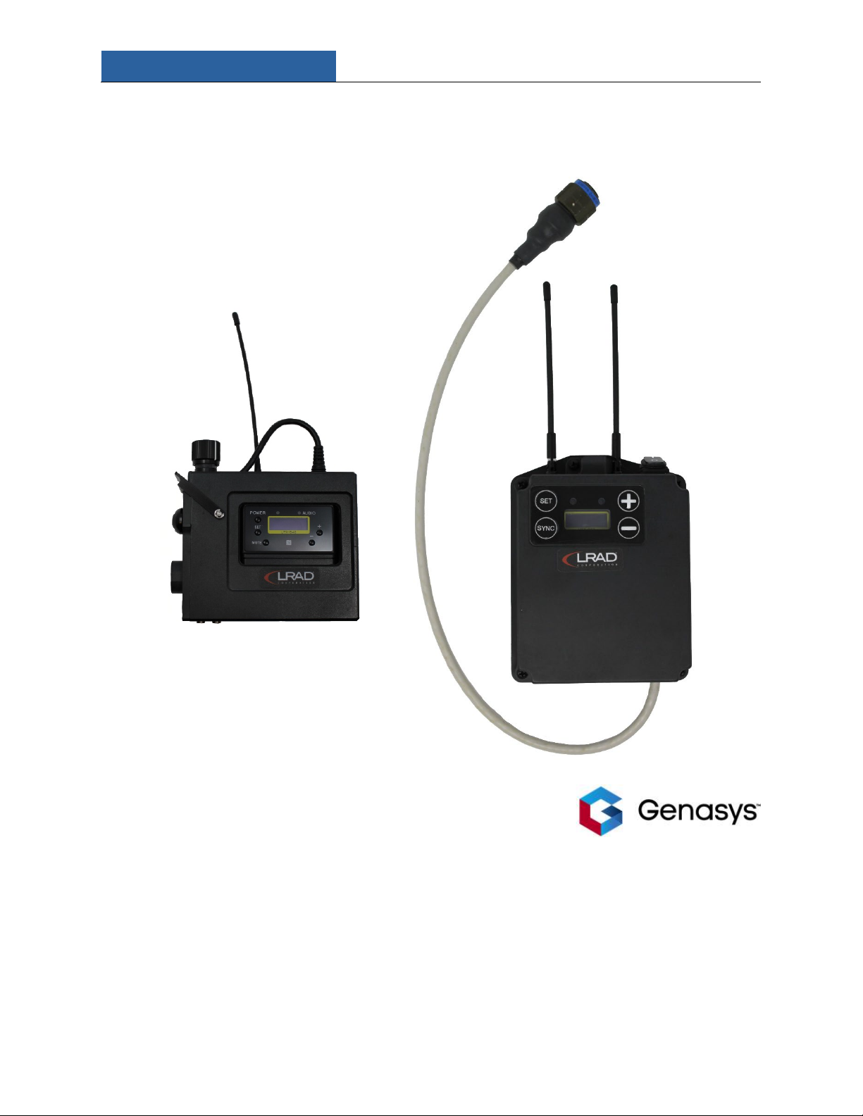
4.1 Wireless Transmitter: UTX-B40............................................................................................ 5
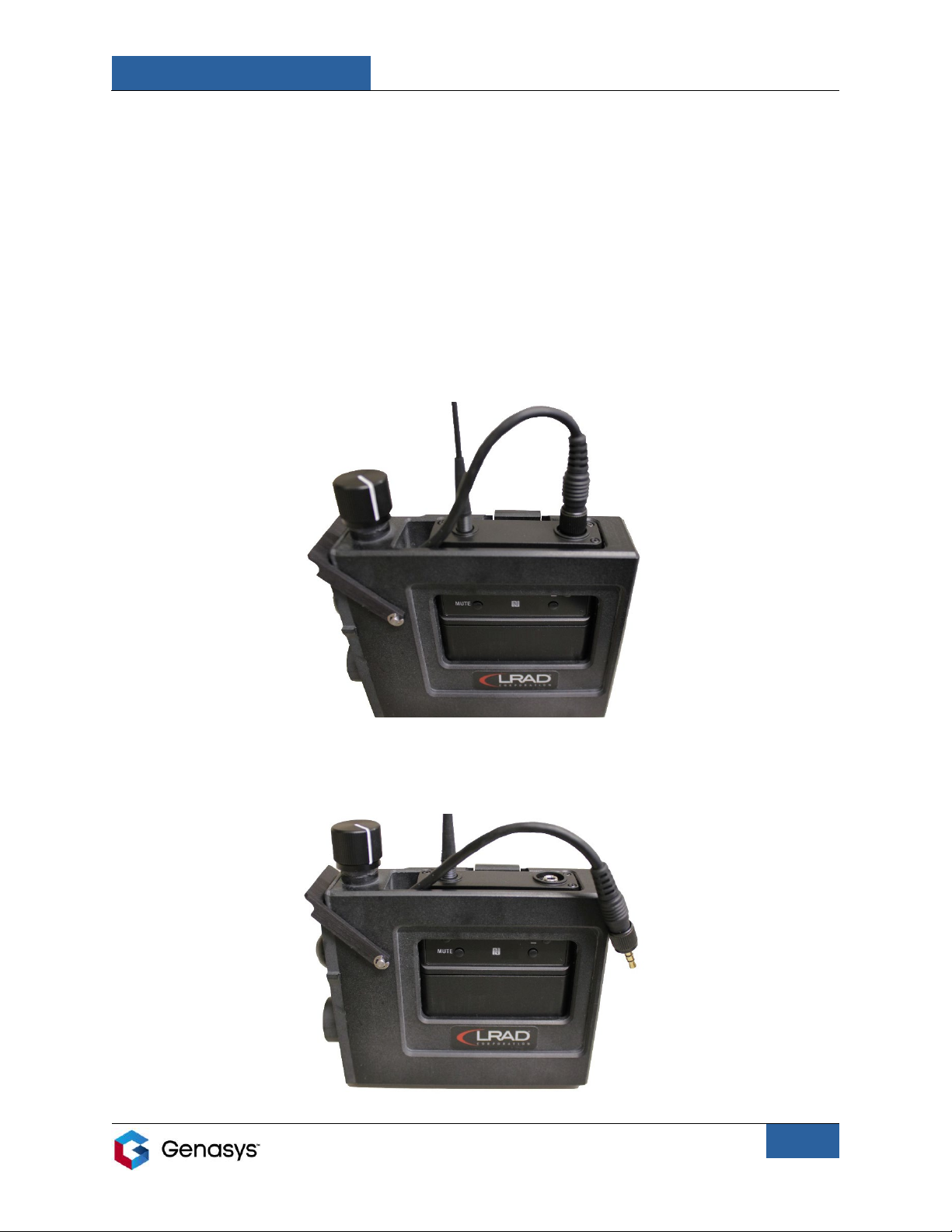
4.1.1 Audio Input.................................................................................................................... 6
4.1.2 Battery Power ............................................................................................................... 6
4.1.3 Battery Access................................................................................................................ 7
4.2 Wireless Receiver: URX-P40................................................................................................. 9
5.0 Setup ...................................................................................................................................... 10
5.1 Belt Pouch Use ................................................................................................................... 11
6.0 Operation ............................................................................................................................... 12
6.1 Important Operational Notes ............................................................................................ 13
7.0 Connection ............................................................................................................................. 14
7.1 Manual Channel Selection ................................................................................................. 14
7.2 Clear Channel Scan............................................................................................................. 16
7.3 Daisy Chain: Connect One Transmitter to Multiple Receivers .......................................... 18
7.4 Further Information ........................................................................................................... 18
8.0 Maintenance and Storage...................................................................................................... 19
9.0 Troubleshooting..................................................................................................................... 20
10.0 Specifications ....................................................................................................................... 22
11.0 Technical Support ................................................................................................................ 23
Figures and Tables
Figure 1: Wireless Transmitter........................................................................................................ 5
Figure 2: Radio Partially Pushed Up................................................................................................ 7
Figure 3: Transmitter Connector Wire Removed from Radio......................................................... 7
Figure 4: Radio Completely Removed from Housing...................................................................... 8
Figure 5: Wireless Receiver............................................................................................................. 9
Figure 6: Setup on LRAD-100X ...................................................................................................... 10
Figure 7: Transmitter Partially in Belt Pouch ................................................................................ 11
Figure 8: Transmitter Completely in Belt Pouch........................................................................... 11
Figure 9: Channel Group ............................................................................................................... 14
Figure 10: Channel Number.......................................................................................................... 15
Figure 11: GP ALL + Section........................................................................................................... 17
Table 1: Various Versions of the Wireless Kit ................................................................................. 2
Table 2: Wireless Kit Parts List ........................................................................................................ 3
Table 3: Audio Input Information ................................................................................................... 6
Table 4: Battery Power Information ............................................................................................... 6
Table 5: Troubleshooting Information.......................................................................................... 20

LRAD WIRELESS KIT
GENASYS INC.
Manual Part No.: 119514-00 Rev. 03
1
1.0 Safety Information
Note the following safety instructions and warnings when assembling, operating, and storing
the LRAD Wireless Kit.
•Read and adhere to the instructions detailed in this manual.
•Keep this manual with the Wireless Kit at all times.
•Make sure all steps are properly followed during assembly and operation. Failure to follow
these steps may result in damage to one or more of the devices included in the Wireless Kit.
•Do not bend, twist, or pinch cables, especially at connection points.
•Make sure all cable connection ports are kept clean and clear of debris.
•Only use Wireless Kit with Genasys products.
•Only use attachments/accessories specified by Genasys.
•Refer all servicing and maintenance to qualified personnel.

LRAD WIRELESS KIT
GENASYS INC.
Manual Part No.: 119514-00 Rev. 03
2
2.0 Introduction
The LRAD Wireless Kit is a Genasys product that allows users to remotely operate their Long
Range Acoustic Device (LRAD). Users of the Wireless Kit can position themselves up to 200
meters from their LRAD, dramatically increasing both range and safety. This adds a heightened
level of flexibility, allowing users to broadcast communications from locations that would
otherwise be inaccessible or dangerous.
Combining state-of-the-art broadcasting technology with ruggedized and weather-resistant
construction, the Wireless Kit can be deployed in environments across the globe.
Available in multiple versions (listed in Table 1), the Wireless Kit is compatible with several
different LRAD models.
The Wireless Kit is the leading product for remotely broadcasting audio in emergency
situations.
Table 1: Various Versions of the Wireless Kit
Catalog Number
Description
WIRELESS-CU-CH14
WIRELESS KIT, LRAD-X, CH14, USA & CANADA
WIRELESS-CU-RES
WIRELESS KIT, LRAD-X, NO RADIOS, RESELLER ONLY, CONTROL UNIT
COMPATIBLE
WIRELESS-MP3-CH14
WIRELESS KIT, FOR MP3, LRAD-X, CH14, USA & CANADA
WIRELESS-MP3-RES
WIRELESS KIT, FOR MP3, LRAD-X, NO RADIOS, RESELLER ONLY

LRAD WIRELESS KIT
GENASYS INC.
Manual Part No.: 119514-00 Rev. 03
3
3.0 Parts Lists
The following table shows the items that are included in the standard Wireless Kit:
Table 2: Wireless Kit Parts List
Part Number
Item Description
Image
119512-00
(CU)
119516-00
(MP3)
RECEIVER ASSY, WIRELESS, FOR
URXP40_14, WATERPROOF, DOME
BUTTONS, LARGE SPREAD
119511-00
TRANSMITTER ASSY, UTX-B40
WIRELESS W/ PTT, ENCLOSED, CH14
108510-00
CABLE ASSY, MICROPHONE,
HEADWORN, DYNAMIC,
HYPERCARDIOID, 3.5MM PLUG
119510-00
BELT POUCH, SONY WIRELESS
TRANSMITTER W/ PTT & TONE
BUTTON, ENCLOSED
108392-10
MP3 PLAYER, SONY WALKMAN, 8GB,
BLACK W/ FILES
108519-00
BATTERY, IND, AA, ALKALINE

LRAD WIRELESS KIT
GENASYS INC.
Manual Part No.: 119514-00 Rev. 03
4
N/A (part of
MP3 player
packing)
USB CABLE
N/A (part of
MP3 player
packing)
AUX CABLE (3.5 MM AUDIO CABLE)
119514-00
MANUAL, PRINTED, LAMINATED, LRAD
WIRELESS KIT, SONY UWP SERIES
119513-00
QUICK INSTALL GUIDE, WIRELESS KIT,
SONY UWP SERIES, PRINTED,
LAMINATED
N/A (part of
Sony packing)
MANUAL, SONY WIRELESS
MICROPHONE PACKAGE
N/A (part of
MP3 player
packing)
MANUAL, SONY MP3 PLAYER

LRAD WIRELESS KIT
GENASYS INC.
Manual Part No.: 119514-00 Rev. 03
5
4.0 System Details
The two main devices included in the Wireless Kit are the transmitter and the receiver. This
section contains important information on these devices that should be understood prior to
operation.
4.1 Wireless Transmitter: UTX-B40
The wireless transmitter sends a signal to the receiver and controls the audio being broadcast
through the LRAD. The transmitter is held by the user.
The following figure highlights the different interfaces located on the transmitter.
Volume
Control
Knob
Audio
Input
Indicator
Light
Power
Indicator
Light
PUSH TO
TALK
Locking
Latch
ALERT
TONE
Button
SET Button
MUTE
Button
Figure 1: Wireless Transmitter
Release Tab
(located on
the rear)
Audio
Inputs:
MIC (left)
and AUX
(right)
SELECTION
Buttons
POWER
Button
Battery
Compartment
(located under
housing)
USB Connector
(located under
housing)
Set Screw
PUSH TO
TALK
Button

LRAD WIRELESS KIT
GENASYS INC.
Manual Part No.: 119514-00 Rev. 03
6
The transmitter is equipped with LED indicator lights that communicate information on the
status of the Wireless Kit.
These indicator lights relay messages regarding battery power and audio input.
4.1.1Audio Input
Table 3: Audio Input Information
Audio Input Indicator Light
Status
Solid Green
Audio input level is appropriate.
Solid Red
Audio input level is too high. If sound is distorted, lower
volume using VOLUME CONTROL knob.
Flashing Orange
Audio is muted. Press MUTE button to enable audio.
Not Illuminated
There is no audio input, or the input level is too low.
4.1.2 Battery Power
Table 4: Battery Power Information
Power Indicator Light
Status
Solid Green
Sufficient battery level.
Flashing Green
Battery level is getting low.
Flashing Orange
Battery is charging. *
Flashing Red
Charging not possible. User must replace batteries. **
Not Illuminated
Power is off or battery is empty.
There are multiple battery options for powering the transmitter. The protocol for charging
and/or replacing batteries will depend on the chosen battery option. The transmitter is
compatible with the following size AA battery types:
•Alkaline LR6 batteries
•Rechargeable nickel metal hydride batteries
•Lithium batteries
*Charging requires rechargeable nickel metal hydride batteries. To charge, the rechargeable batteries
must be inserted in the transmitter, and the transmitter’s power must be off. Then connect the
transmitter to a power source via USB cable.
**Charging is not possible with alkaline or lithium batteries, or if the rechargeable batteries have
deteriorated.

LRAD WIRELESS KIT
GENASYS INC.
Manual Part No.: 119514-00 Rev. 03
7
4.1.3 Battery Access
The transmitter is made up of two components: the radio and the housing. The radio sits inside
of the housing. The radio contains the battery compartment and USB connector.
Users will need to remove the radio from the housing in order to replace and/or charge the
batteries. To access the radio, perform the following steps.
NOTE: DO NOT pull on the antenna to remove the radio. Doing so will damage the device.
1. Pull the release tab on the rear of the housing and push the radio up using both thumbs
until the locking connecter on the top can be accessed, as seen in the figure below.
2. Unscrew and remove the 3.5-millimeter connector cable from the radio.
Figure 2: Radio Partially Pushed Up
Figure 3: Transmitter Connector Wire Removed from Radio

LRAD WIRELESS KIT
GENASYS INC.
Manual Part No.: 119514-00 Rev. 03
8
3. Remove the radio completely from the housing. This will allow access to the battery
compartment, located on the front of the radio, and the USB connector, located on the left
side.
IMPORTANT NOTES:
•There may be some resistance when removing the radio from the housing. This is normal. If
resistance prevents the removal of the radio, loosen the set screw on the right side of the
housing using a 5/64-inch hex key.
•When replacing the radio in the housing, ensure the 3.5-millimeter connector cable is
completely tightened. If the cable is not tightly connected it may affect broadcast quality
and/or damage the transmitter.
Figure 4: Radio Completely Removed from Housing

LRAD WIRELESS KIT
GENASYS INC.
Manual Part No.: 119514-00 Rev. 03
9
4.2 Wireless Receiver: URX-P40
The receiver is plugged into the LRAD and relays audio sent from the transmitter to be
broadcast through the LRAD.
The following figure highlights the different interfaces located on the receiver.
The receiver connects directly to the LRAD. The receiver is powered by the LRAD and does not
require batteries.
*There are two types of receivers: one that has a POWER switch, and one that does not. Your
receiver will depend on your LRAD. Note how power is controlled on your LRAD.
•If your LRAD does not have a POWER switch, then you will need a receiver with a
POWER switch.
•If your LRAD has a POWER switch, then you will need a receiver without a POWER
switch.
POWER
Switch
(Conditional)*
Figure 5: Wireless Receiver
SELECTION
Buttons
SYNC
Button
Audio
Cable
SET Button

LRAD WIRELESS KIT
GENASYS INC.
Manual Part No.: 119514-00 Rev. 03
10
5.0 Setup
1. Connect receiver to LRAD. Connect audio cable from receiver to audio input connector on
LRAD.
•Refer to (A) in Figure 6.
2. Attach receiver to LRAD using head unit mounting clip, located on the top of the LRAD.
•Refer to (B) in Figure 6.
3. Connect transmitter to audio source.
i. Connect headworn microphone to transmitter. Insert headworn microphone cable into
MIC audio input connector.
•Refer to (C) in Figure 6.
AND/OR
ii. Connect transmitter to external audio device (ex. MP3 Player) using AUX cable. Insert
one end of the AUX cable into external audio device and the other end into AUX audio
input connector.
•Refer to (D) in Figure 6.
C
D
Figure 6: Setup on LRAD-100X
A
B

LRAD WIRELESS KIT
GENASYS INC.
Manual Part No.: 119514-00 Rev. 03
11
5.1 Belt Pouch Use
The belt pouch allows the user to secure the transmitter to their waist, freeing up their hands
for more flexibility while operating the Wireless Kit. The belt pouch is designed to fit tightly
around the transmitter.
To use the belt pouch, perform the following steps.
1. Unsnap the pouch’s strap and position the pouch with the buckle facing the user.
2. Insert the bottom-left corner of the transmitter into the pouch first, so that the ALERT TONE
button fits through the opening on the left side of the pouch (Figure 7).
3. Pull the right side of the pouch up over the bottom-right corner of the transmitter until fully
seated. Snap the pouch’s strap into place (Figure 8).
4. Slide belt pouch onto the user’s belt through the loop on the back of the pouch.
Figure 7: Transmitter Partially in Belt Pouch
Figure 8: Transmitter Completely in Belt Pouch

LRAD WIRELESS KIT
GENASYS INC.
Manual Part No.: 119514-00 Rev. 03
12
6.0 Operation
Once the Wireless Kit items have been properly connected, perform the following steps to
operate the system.
1. Ensure that the volume is set to minimum. Do this by turning the transmitter’s VOLUME
CONTROL knob counterclockwise.
2. Turn on the receiver and LRAD.
•Depending on the Wireless Kit and LRAD model being used, this will require turning
on a POWER switch located on either the receiver or the LRAD.
3. Turn on the transmitter. Press and hold the POWER button.
•If there are issues turning on the transmitter, check batteries.
4. Ensure that the transmitter’s channel matches that of the receiver and that the two devices
are connected.
•Learn more in the “Connection” section.
5. Broadcast audio through the Wireless Kit and LRAD. Adjust transmitter’s VOLUME CONTROL
knob to reach the desired volume level.
i. Broadcast spoken audio: Press and hold the PUSH TO TALK (PTT) button and speak
directly into the headworn microphone.
•For optimal performance, position mouth as close to the microphone as
possible.
•For continuous, hands-free transmission of spoken audio: Pull locking latch
down onto PTT button.
ii. Broadcast a pre-recorded alert sound: Press ALERT TONE button.
iii. Broadcast audio from an external audio device: Initiate playback of audio on
external audio device.
•Transmitter can play audio from various types of devices (MP3 Player, cell
phone, tablet, etc.), as long as the device is compatible with the AUX audio
input.
6. To power down the Wireless Kit, first turn off the transmitter by holding the POWER button.
Then turn off the receiver and LRAD using the POWER switch.
•Failure to follow this order may cause damage to the Wireless Kit.
•Transmitter’s batteries will drain if transmitter is not turned off.

LRAD WIRELESS KIT
GENASYS INC.
Manual Part No.: 119514-00 Rev. 03
13
6.1 Important Operational Notes
•Adjust volume carefully. Feedback can occur if microphone is near the LRAD while operating
at high volume.
•Press MUTE button to mute and unmute audio.
•PTT button does not need to be pressed to play alert tone or audio from external audio
device.
•Audio from MIC and AUX inputs are mixed and will broadcast simultaneously if audio is
coming into both inputs.
•If there are interference issues, the user may need to change the channel group and
channel number to find a clear frequency. It is suggested that the user perform a clear
channel scan.
oLearn more in the “Clear Channel Scan” subsection.
•Always keep the receiver’s two antennas in the upright position.
•Never carry the receiver by audio cable or antennas.
•Never carry transmitter by antenna.

LRAD WIRELESS KIT
GENASYS INC.
Manual Part No.: 119514-00 Rev. 03
14
7.0 Connection
For the Wireless Kit to function, the receiver and transmitter must be properly connected. This
is achieved by matching the channel group and channel number on both devices. These figures
are displayed, for both the receiver and the transmitter, in the Group/Channel menu (GP/CH
menu). This is the default menu that appears when the devices are turned on. The GP/CH menu
is shown in Figures 9 and 10.
NOTE: Receivers and transmitters can only operate on channels in their given frequency range.
This range depends on the location of the user. For more information on frequency ranges
consult the Sony Wireless Microphone Package Manual, which is included as part of the LRAD
Wireless Kit.
7.1 Manual Channel Selection
Manually selecting the channel allows the user to scroll through available channels and select
the exact channel they would like to use to connect the receiver and transmitter.
To execute a manual channel selection, perform the following steps:
Manual Channel Selection on Receiver:
1. Power on the receiver and make sure the screen displays the GP/CH menu (the default
menu).
•If this menu is not displayed, use the SELECT buttons (+ and -) to scroll through
menus.
2. Press and hold the SET button until the channel group starts flashing (Figure 9).
3. Use the SELECT buttons to scroll through channel groups. Then press the SET button to
choose the desired channel group. The channel group is now set.
Figure 9: Channel Group

LRAD WIRELESS KIT
GENASYS INC.
Manual Part No.: 119514-00 Rev. 03
15
4. Once the channel group is set, the channel number will start flashing (Figure 10).
5. Use the SELECT buttons to scroll through channel numbers. Then press the SET button to
choose the desired channel number. The channel number is now set and the screen will
stop flashing.
Manual Channel Selection on Transmitter:
1. Power on the transmitter by pressing and holding both the POWER button and the SET
button.
•If SET button is not pressed when powering on the transmitter, you will not be able
•to change the channel group and channel number.
2. Make sure the screen displays the GP/CH menu.
•If this menu is not displayed, use the SELECT buttons to scroll through menus.
3. Press and hold the SET button until the channel group starts flashing (Figure 9).
4. Use the SELECT buttons to scroll through channel groups. Then press the SET button to
choose the desired channel group. The channel group is now set.
5. Once the channel group is set, the channel number will start flashing (Figure 10).
6. Use the SELECT buttons to scroll through channel numbers. Then press the SET button to
choose the desired channel number. The channel number is now set and the screen will
stop flashing.
Figure 10: Channel Number

LRAD WIRELESS KIT
GENASYS INC.
Manual Part No.: 119514-00 Rev. 03
16
•Make sure that the channel group and channel number, and therefore the frequency
(displayed at the bottom of the GP/CH menu), match exactly on both the transmitter and
the receiver.
•If the channel group and channel number match, the transmitter and receiver should
successfully connect.
•If the the transmitter and receiver are connected, black bars will appear on the right side of
the screen (as seen in Figures 9, 10, and 11).
oThese bars display the A and B tuner signal strength meters. The Wireless Kit will
always transmit broadcasts using the strongest of the two signals.
oAlso on this screen are the audio level (top-left) and the battery level (top-right).
•If the channel group and channel number match but the transmitter and receiver do not
connect, cycle the transmitter’s power (turn the transmitter off and back on). This should
connect the two devices.
7.2 Clear Channel Scan
Along with manually choosing the desired channel, users also have the option of performing a
clear channel scan.
By initiating a clear channel scan, the user is tasking the receiver to scan for the best available
channel in a given channel group. The scan seeks out the quietest channel in order to ensure
audio is relayed clearly from the transmitter to the receiver.
To initiate a clear channel scan, perform the steps listed on the following page.
NOTE: The desired channel group must already be selected before performing the clear channel
scan.

LRAD WIRELESS KIT
GENASYS INC.
Manual Part No.: 119514-00 Rev. 03
17
Clear Channel Scan on Receiver:
1. Use the SELECT buttons to scroll through menus until the CLR CH SCAN menu is displayed.
2. Press and hold the SET button until the GP ALL + section starts flashing (Figure 11).
3. Press the (+)SELECT button. This will initiate the clear channel scan.
•The first clear channel number available will flash on the screen.
•To display the next available clear channel number, press the (+)SELECT button.
•To cancel searching press the (-)SELECT button.
4. Press the SET button when the desired channel number is displayed. The receiver’s channel
is now set, and the screen will stop flashing.
Clear Channel Scan on Transmitter:
1. Manually set the channel group and channel number to match that of the receiver.
2. After matching the channel group and channel number on both devices, cycle the
transmitter’s power. This should connect the two devices.
Figure 11: GP ALL + Section
Other manuals for LRAD
2
Table of contents