Anaren A8520E24A91 User manual

Anaren Integrated Radio
A8520E24A91 Users
Manual
Release Date Dec 27
th
2010

Page ii of 28 A8520E24A91 – Users Manual
Release Date: Dec 27th 2010
THIS PAGE LEFT INTENTIONALLY BLANK

iii
Users Manual
Model A8520E24A91
Contents
1.
Overview ..........................................................................................................................................................5
1.1.
Features.......................................................................................................................................................6
2.
Theory of Operation........................................................................................................................................6
2.1.
Network Topology and Nomenclature..................................................................................................9
2.2.
Adaptive Frequency Hopping...............................................................................................................10
2.3.
Applications.............................................................................................................................................13
3.
Product Approvals........................................................................................................................................13
3.1.
USA (Federal Communications Commission, FCC, ) ..................................................................13
3.1.1.
FCC Labeling Requirements .............................................................................................................14
3.1.2.
End User Manual..............................................................................................................................14
3.1.3.
RF Exposure......................................................................................................................................15
3.2.
Canada (Industry Canada, IC)...............................................................................................................15
3.3.
Potential Interference Sources ...............................................................................................................17
4.
Electrical Characteristics ..............................................................................................................................18
4.1.
Absolute Maximum Ratings..................................................................................................................18
4.2.
Operating Conditions .............................................................................................................................19
4.3.
Pin Out......................................................................................................................................................19
4.4.
Recommended Layout............................................................................................................................22
4.5.
Power Supply Considerations...............................................................................................................23
5.
Configuration and Programming ...............................................................................................................24
5.1.
Calibrating Transmit Power ..................................................................................................................24
5.2.
Programming...........................................................................................................................................25

Page iv of 28 A8520E24A91 – Users Manual
Release Date: Dec 27th 2010
THIS PAGE LEFT INTENTIONALLY BLANK

A8520E24A91 – Users Manual Page 5 of 28
Release Date: Dec 27th 2010
1. Overview
The A8520E24A91 series modules are surface mount modules integrating a CC85xx
PurePath™ wireless audio transceiver with the CC2591 PA/LNA device for increased range
and an integral antenna. The module incorporates a crystal, the required RF matching and
filtering for FCC compliance as well as filtering on all digital lines for noise reduction and
sensitivity. The modules operate in the global non-licensed 2.4GHz ISM/SRD frequency band.
These radio modules are ideal for achieving low power, long range wireless connectivity without
having to deal with extensive Protocol, RF, antenna design and regulatory compliance, allowing
quick time to market. The modules are 100% tested to provide consistent performance.
The A8520E24A91 series modules have received regulatory approvals for modular devices in
the United States (FCC) and Canada (IC). The modular approval allows the end user to place
an A8520E24A91 module inside a finished product without having to perform costly regulatory
testing for an intentional RF radiator. Section 3 has information on the requirements for the end
user/integrator must fulfill to use the modules without intentional radiator regulatory testing.
The A85xxE91A91 is based on the CC85xx series chips and the CC2591 chip, both from Texas
Instruments. All control lines are provided at module level for full control of its operation. Please
see the CC85xx and CC2591 data sheet (www.ti.com) for how to operate, program and control
the module. The PurePath™ protocol is developed, by Texas Instruments, specifically for the
CC85xx series chips and specifically for digital audio distribution. At the extremes of its range,
the protocol provides graceful degradation of the audio signal usign algorithms like interpolation,
to make intermittent connectivity inaudible. Thus the A8520E24A91 series modules are not
suitable for strict data transport.
The module/protocol is configured and programmed by the OEM/Integrator to setup the specific
Codec chip used for audio conversion and to setup control buttons and manufacturer/network
addresses. This is described in detail in the CC85xx datasheet, users guide and PurePath™
documentation on Texas Instruments web (www.ti.com). Specifics pertaining to calibrating the
transmit power from the module is covered in section 5.1.
The A8520E24A91 module measures 11x19x2mm and are footprint compatible with other
family members:
A85xxE24A90 – ETSI compliant version similar to the A8520E24A91.
A85xxR24A00 – Lower power consumption, shorter range modulens.

Page 6 of 28 A8520E24A91 – Users Manual
Release Date: Dec 27th 2010
1.1. Features
Features:
Un-Compressed Wireless Audio
Connectivity
Pre-defined protocol
Configurable human interface
Autonomous or Hosted mode
Benefits Summary:
Operating temperature -40 to +85C
100% RF Tested in production for
repeatable performance
Common footprint for multiple family
members
No RF engineering experience
necessary
No protocol experience necessary
Only requires a 2 layer Host PCB
implementation
FCC & IC certified
No regulatory “Intentional radiator”
testing required to integrate module
into end product. Simple certification
labeling replaces testing.
2. Theory of Operation
The A8520E24A91 interfaces directly to a audio Codec chip through the I2S for audio data and
though I2C fro volume control and other Codec chip settings.
Below a block diagram is given for the A8520E24A91 module.
Antenna
oThe antenna couples energy between the air and the module. The integral
antenna provides a near omni-directional antenna pattern with high efficiency;
such that the application will work equally well in any direction. Note that the end
radiation pattern depend not only on the antenna, but also the ground plane,
enclosure and installation environment.
Filtering
oFiltering removes spurious signals to comply with regulatory intentional radiator
requirements as well as provide reduced susceptibility to power supply and
digital noise, as well as filter out RF and high frequency noise from the digital
audio and control link (I2S, I2C).
Matching
oThe matching provides the correct loading of the transmit amplifier to achieve the
highest output power as well as the correct loading for the receive LNA to
achieve the best sensitivity.
Protocol

A8520E24A91 – Users Manual Page 7 of 28
Release Date: Dec 27th 2010
oThe protocol implements an entire wireless audio transport mechanism with
adaptive frequency usage, retransmission of lost packets as well as a low data
rate link for remote control purposes.

Page 8 of 28 A8520E24A91 – Users Manual
Release Date: Dec 27th 2010
Figure 1 the functionality of the A8520E24A91, using an integral antenna
CC259x
CC85xx
Bias RF
RF
AVdd
HGM
PAEN
EN
XPAEN/GIO14
XLNAEN/GIO15
AVdd
AVdd
DVdd
IOVdd
AD1
AD2/GIO9
AD0
WCLK
BCLK
MCLK
RSTN
GIO3
GIO2
GIO1
MOSI
SCLK
CS_N
MISO
XANTP/USBP
XANTN/USBM
GIO13
GIO12
SDA
SCL
VBAT
100k
29
32
33
4
28
27
26
25
24
23
21
9
20
19
18
17
16
15
14
13
8
7
6
5
11
10
2
3
1
22
12
30
34
100k
DNC (AVdd_CC259x)
VBAT
SCL
SDA
GIO12
GIO13
XLNAEN/GIO15
XPAEN/GIO14
GND
DNC (RF-Test)
GND
GND
GND
GND
GND 31 HGM
Vdd
IOVdd
AD2/GIO9
AD1
AD0
WCLK
BCLK
MCLK
RSTN
GIO3
GIO2
GIO1
MISO
MOSI
SCLK
CS_N
XANTP/USBP
XANTN/USBM
X1
X0
48MHz
100k

A8520E24A91 – Users Manual Page 9 of 28
Release Date: Dec 27th 2010
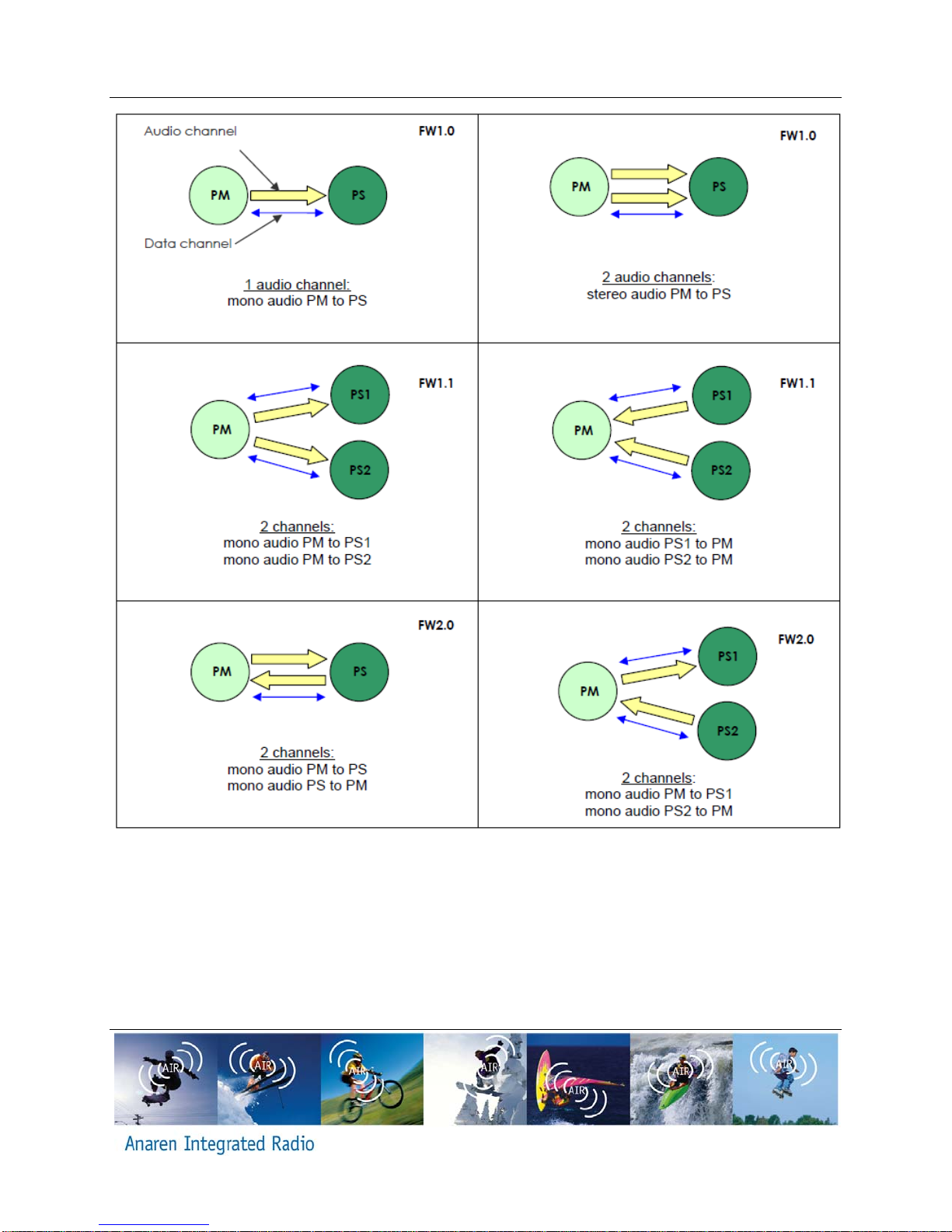
2.1. Network Topology and Nomenclature
A A8520E24A91 network consists of one Protocol Master (PM) and one or two Protocol
Slave(s) (PS). The PM provides the audio reference clock and controls network association.
The PS regenerate the audio reference clock based on the packets received. Audio can be
transmitted from the PM to a PS. The device receiving the audio is called an Audio Sink, the
device sending the audio is called an Audio Source. A device can be both Audio Sink and Audio
Source at the same time (bidirectional audio will be supported in future revisions of the
firmware). The CC8520 network also includes a Data Side-Channel which is a bi-directional
data link between the PM and all PS in the network. This is further described in chapter 8.
Error! Reference source not found. Illustrates the different network topologies that can be
formed with CC8520 using the different firmware versions.
Page 10 of 28 A8520E24A91 – Users Manual
Release Date: Dec 27th 2010
Figure 2 A8520E24A91 topologies supported for different A8520E24A91 FW revisions
2.2. Adaptive Frequency Hopping
The purpose of using frequency hopping in a radio system is to provide diversity that allows
data throughput to be maintained even if interfering radio systems or the physical environment
(e.g. multipath fading) renders some RF channels unusable. In the 2.4 GHz ISM band, the
sheer amount of radio systems and the severity and dynamic nature of indoor fading
phenomena in typical operating environments require the use of this kind of diversity if a
Other manuals for A8520E24A91
1
Table of contents
Other Anaren Radio manuals

Anaren
Anaren A1101R09x User manual

Anaren
Anaren A110LR09x User manual

Anaren
Anaren A2500R24x User manual

Anaren
Anaren A8520E24A91 User manual

Anaren
Anaren A1101R04C User manual

Anaren
Anaren A1101R04C00GM User manual

Anaren
Anaren A2541R24x User manual

Anaren
Anaren A1101R09 Series User manual

Anaren
Anaren A2530E24x User manual


