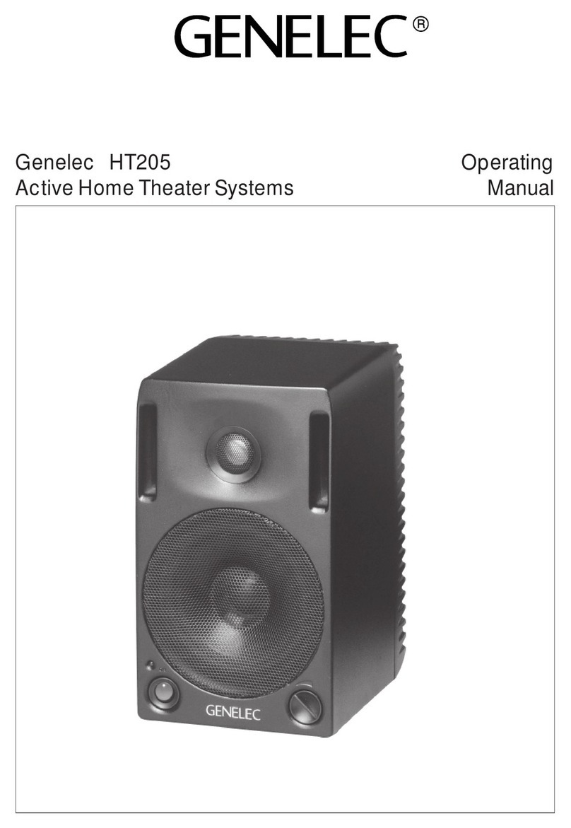
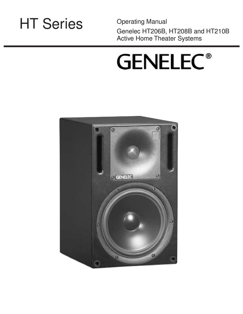
Genelec HT208 User manual

Genelec HT208 and HT206
Active Home Theater Systems Operating
Manual

1. General description1. General description
1. General description1. General description
1. General description
SystemSystem
SystemSystem
System
Thebi-amplifiedGENELECHT206and
HT208 are two way active speakers
designedforhighqualityHomeTheater
systems.
Designedasanactivespeakers,these
unitscontaindrivers,poweramplifiers,
activecrossoverfilteringandprotection
circuitry. The Directivity Control
Waveguide (DCW) technology used
provides excellent frequency balance
evenindifficultacousticenvironments.
DriversDrivers
DriversDrivers
Drivers
The HT208 has a 210 mm (8") bass
driverandthelowfrequencyresponse
extends down to 43 Hz (-6dB). The
HT206 has a 170 mm (61/2")driverwith
-6dB point at 47 Hz.
The high frequency driver is a 25 mm
(1") (HT208) or a 19 mm (3/4") (HT206)
metal dome. The uniform dispersion
control is achieved with the
revolutionary DCW technology
pioneered by Genelec. This has also
resulted in perfect phase and delay
uniformity at the crossover frequency.
The bass and treble drivers are
magneticallyshieldedonbothmodels.
CrossoverCrossover
CrossoverCrossover
Crossover
The amplifier unit contains an active
crossover. This is the ideal method for
dividing the input signal between the
driver units, allowing the overall
responseofthesystemtobeoptimized
to an extent impossible with a passive
system.
Tomaintainuniformfrequencybalance
in differing acoustic environments,
three special calibrated controls are
included in the active crossover
network:trebleandbass'tilt' andbass
'roll-off' switches, which make
adjustmentsin2 dBsteps(seeFig.1).
AmplifiersAmplifiers
AmplifiersAmplifiers
Amplifiers
The amplifier unit is mounted to the
rearofthespeakerenclosure.Boththe
bassandtrebleamplifiersontheHT208
produce 120 W of short term power.
TheHT206hasa80 Wamplifierforthe
bass and 50 W amplifier for the treble
driver.Bothunitsincorporateprotection
circuitry for driver overload protection
and amplifier thermal overload
protection. Variable input sensitivity
allows for accurate level matching to
the decoder or preamplifier.
Figure 2. Speaker acoustic axis in horizontal and vertical mounting positions.
Figure 1. Suggested tone control setting for differing acoustic environments
noitisoPgnitnuoMrekaepS elberT
tliT
ssaB
tliT
ssaB
ffo-lloR
esnopserciohcenatalFenoNenoNenoN
moordepmadanignidnatseerFenoNBd2-enoN
moortnarebreveranignidnatseerFenoNBd4-Bd2-
renrocanIenoNBd4-Bd4-
tenibacanIenoNBd2-Bd2-
HT208 also features an "autostart"
function. "Autostart" turns off the
amplifierifthereisnosignalpresentfor
about 5 minutes. When the signal
returns the amplifier switches on
immediatelyandthespeakerfunctions
normally. This function should be
enabledwhenthespeakerisleftturned
on even when not in use; power is
saved when the amplifier is switched
off.AnindicatorLEDontheDCWplate
shows the system status.
"Autostart"canbeenabledordisabled
as required by using the dip switch on
the speaker back panel (see fig.4).
2. Installation2. Installation
2. Installation2. Installation
2. Installation
Place the loudspeaker in its required
position, taking note of the line of the
listening axis (see figures 2 and 3). To
ensure cooling, there should be a
clearance of more than 4" (10 cm)
between speaker backplate and any
solid surface. Before connecting up,
ensurethat themains switchis off(see
figure4).Checkthatthemainsvoltage
selector is correctly set and that the
appropriate fuse is fitted.
Figure 3. Recommended speaker
alignment in a 5.1-channel Surround
Sound System.
Audio input is made via a 10 kOhm
balanced(XLR)ORunbalanced(RCA)
connector (see fig. 4). If the signal
sourcehassuitablebalancedoutputs,
we recommend the use the XLR
connector and balanced interconnect
cablesduetotheirbetterresistanceto
interference. Once connection has
beenmade,thespeakers are ready to
be powered-up.

Setting the input sensitivitySetting the input sensitivity
Setting the input sensitivitySetting the input sensitivity
Setting the input sensitivity
Adjustment of the input sensitivity of
each speaker can be made to match
thatof the decoderorother source,by
use of the input sensitivity control on
the rear panel (see figure 4). A small
screwdriver is needed for the
adjustment. The manufacturer default
setting for this control is -6 dBu (fully
clockwise) which gives SPL of 100 dB
@1m with -6 dBu input level. Note that
to get the full output level of 110 dB
SPL,aninputlevelof+4dBuisneeded
in this setting.
Setting the tone controlsSetting the tone controls
Setting the tone controlsSetting the tone controls
Setting the tone controls
The acoustic response of the system
mayalsohavetobeadjustedtomatch
the acoustic environment. The
adjustmentisdonebysettingthethree
tone control switches 'treble tilt', 'bass
tilt' and 'bass roll-off' on the rear panel
of the amplifier. The manufacturers
default settings for these controls are
'AllOff'togiveaflatanechoicresponse.
SeeFigure1forsuggestedtonecontrol
settings in differing acoustic
environments. Figures 5 and 6 show
the effect of the controls on the
anechoic response. Always start
adjustment by setting all switches to
the 'OFF' position. Then set only one
switch to the 'ON' position to select
response curve needed. If more than
one switch is set to 'ON' (within one
switch group) the attenuation value is
not accurate.
Vertical / horizontal mountingVertical / horizontal mounting
Vertical / horizontal mountingVertical / horizontal mounting
Vertical / horizontal mounting
The speakers are normally delivered
for vertical mounting. If horizontal
mounting is needed the DCW plate
can be rotated so that the GENELEC
logoislocatedatthebottomleftcorner
of the DCW. Remove the four corner
screws of the DCW and pull the plate
carefullyoutwithoutstressingthewires
and the gasket. Rotate the plate 90
degrees to the appropriate direction
and remount the screws. Note that to
obtain a mirror image pair the DCW's
must be rotated 90° in opposite
directions on both speakers. In
horizontal mounting position the bass
drivers should point inwards to get
better low frequency summing.
Figure 4. HT208 rear panel layout.
Status indicator LEDStatus indicator LED
Status indicator LEDStatus indicator LED
Status indicator LED
Thestatusindicator LEDonthe HT208
changes colour to indicate amplifier
status. If the LED is yellow, it indicates
that the "autostart" function has turned
the amplifier off. The amplifier returns
to "ON" mode and the LED changes to
green colour automatically when the
signal returns. If the LED turns red, it
indicates that the amplifier thermal
protection circuit has been activated.
Let the amplifier cool down and check
thatthereissufficientclearancearound
the amplifier for cooling.
TheHT206doesnothavetheautostart
function, so it has only a green "ON"-
LED to indicate that the power has
been switched on.
3. Maintenance3. Maintenance
3. Maintenance3. Maintenance
3. Maintenance
There are no user serviceable parts
within the loudspeaker. Any
maintenance or repair should only be
undertaken by qualified service
personnel. Ensure that if fuse
replacement is required, only fuses of
the appropriate voltage and current
ratings are used. REMEMBER to
disconnect the power supply by
removalofthemainscablebeforefuse
replacement.
4. Safety Considerations4. Safety Considerations
4. Safety Considerations4. Safety Considerations
4. Safety Considerations
1. Servicing and adjustment must
only be performed by qualified
service personnel. Opening the
amplifier's rear panel is strictly
prohibited.
2. It is forbidden to use this product
with an unearthed mains cable,
whichmayleadtopersonalinjury.
3. To prevent fire or electric shock,
donot expose theunitto water or
moisture.
WARNING!WARNING!
WARNING!WARNING!
WARNING!
This equipment is capable ofThis equipment is capable of
This equipment is capable ofThis equipment is capable of
This equipment is capable of
delivering Sound Pressure Levels indelivering Sound Pressure Levels in
delivering Sound Pressure Levels indelivering Sound Pressure Levels in
delivering Sound Pressure Levels in
excess of 85 dB, which may causeexcess of 85 dB, which may cause
excess of 85 dB, which may causeexcess of 85 dB, which may cause
excess of 85 dB, which may cause
permanent hearing damage.permanent hearing damage.
permanent hearing damage.permanent hearing damage.
permanent hearing damage.
5. Guarantee5. Guarantee
5. Guarantee5. Guarantee
5. Guarantee
This product is supplied with a two
yearguaranteeagainstmanufacturing
faults or defects that might alter the
performance of the unit. Refer to
supplier for full sales and guarantee
terms.

Figure 5. The effect of the 'treble tilt', 'bass tilt' and 'bass roll-off'
controls on the free field response of the HT208.
SYSTEM SPECIFICATIONSSYSTEM SPECIFICATIONS
SYSTEM SPECIFICATIONSSYSTEM SPECIFICATIONS
SYSTEM SPECIFICATIONS
Figure 6. The effect of the 'treble tilt', 'bass tilt' and 'bass roll-off'
controls on the free field response of the HT206.
HT206HT206
HT206HT206
HT206 HT208HT208
HT208HT208
HT208
Free field frequency response of system: 55 Hz - 18 kHz (±2,5 dB) 48 Hz - 22 kHz (±2 dB)
Maximum peak acoustic output per pair
@ 1m measuring distance with music material: >115 dB SPL >120 dB SPL
Self generated noise level in free field @ 1m on axis: <10 dB (A-weighted) <10 dB (A-weighted)
Drivers Bass: 170 mm (61/2") 210 mm (8")
Treble: 19 mm (3/4") metal dome 25 mm (1") metal dome
Magnetic shielding: Standard Standard
Bass amplifier output power: Short term 80 W Short term 120 W
Treble amplifier output power: Short term 50 W Short term 120 W
Amplifier system distortion at nominal output
THD: <0.08% <0.05%
SMPTE-IM: <0.08% <0.05%
CCIF-IM: <0.08% <0.05%
DIM 100: <0.08% <0.05%
Harmonic distortion at 90 dB SPL @ 1 m on axis: < 3% (60...150 Hz) < 1% (50...100 Hz)
< 0,5% (> 150 Hz) < 0,5% (>100 Hz)
Input impedance: 10 kOhm 10 kOhm
Crossover frequency: 3.5 kHz 2.2 kHz
Treble tilt control in 2dB steps from +2 to -4dB & MUTE: @15 kHz @15 kHz
Bass roll-off control in 2 dB steps from 0 to -8 dB: @50 Hz @40 Hz
Bass tilt control in 2 dB steps from 0 to -6 dB & MUTE: @100 Hz @80 Hz
Mains voltage: 100/200V or 115/230V 100/200V or 115/230V
Power consumption (Idle / Full output): 20 / 100 W 30 / 160 W
Weight: 7,6 kg (17 Ib.) 12,7 kg (28 Ib.)
Dimensions Height: 312 mm (12 1/4") 395 mm (15 9/16")
Width: 200 mm (7 7/8") 250 mm (9 7/8")
Depth: 240 mm (9 7/16") 290 mm (11 7/16")
Genelec Document DRHT208001Genelec Document DRHT208001
Genelec Document DRHT208001Genelec Document DRHT208001
Genelec Document DRHT208001
COPYRIGHT GENELEC OY 1999COPYRIGHT GENELEC OY 1999
COPYRIGHT GENELEC OY 1999COPYRIGHT GENELEC OY 1999
COPYRIGHT GENELEC OY 1999
All data subject to change without prior noticeAll data subject to change without prior notice
All data subject to change without prior noticeAll data subject to change without prior notice
All data subject to change without prior notice
Note! All frequency response curves were measured in a
calibrated,12 mcube, anechoicchamber at1 musing grade
1 measuring equipment. Input signal levels were set at -20
dBu. The anechoic chamber error in the free field response
is less than 0.5 dB down to 60 Hz.
Genelec Oy, Olvitie 5
FIN - 74100 IISALMI, FINLAND
Phone: + 358 17 83 881
Fax: +358 17 812267
Email: [email protected]
Web: www.genelec.com
Genelec Inc., 7 Tech Circle
NATICK, MA 01760, U.S.A.
Phone: +1 508 652 0900
Fax: +1 508 652 0909
Email: genelec.usa@genelec.com
This manual suits for next models
1
Other Genelec Home Theater System manuals
