Genelec HT205 User manual

Genelec HT205
ActiveHomeTheaterSystems Operating
Manual
1. General description1. General description
1. General description1. General description
1. General description
SystemSystem
SystemSystem
System
The bi-amplified GENELEC HT205 is
atwowayactivespeakerdesignedfor
high quality Home Theater systems.
Designed as an active speaker, this
unitcontainsdrivers,poweramplifiers,
active crossover filters and protection
circuitry. The Directivity Control
Waveguide (DCW) technology used
provides excellent frequency balance
evenindifficultacousticenvironments.
Integrated ConstructionIntegrated Construction
Integrated ConstructionIntegrated Construction
Integrated Construction
As the amplifiers are built into the
speaker enclosure, the only
connections required are the mains
supply and the line level input signal,
making the HT205 very easy to set up
anduse. Theintegrateddesignallows
the amplifiers and the drivers to be
calibratedasasingleunitinthefactory.
This eliminates the effects of
component tolerances and ensures
consistentquality. Thecastaluminium
cabinet has rounded corners and a
hard-wearing painted outer surface.
DriversDrivers
DriversDrivers
Drivers
Thebass frequenciesare reproduced
by a 130 mm (5") bass driver mounted
ina4.5litre ventedcabinet. The-3 dB
point lies at 68 Hz and the frequency
response extends down to 65 Hz
(-6 dB).
The high frequency driver is a 19 mm
(3/4") metal dome. Uniform dispersion
control is achieved with the
revolutionary DCW Technology
pioneeredbyGenelec,whichhasalso
resulted in perfect phase and delay
uniformity at the crossover frequency.
Both drivers are magnetically
shielded.
CrossoverCrossover
CrossoverCrossover
Crossover
The amplifier unit contains an active
crossover. This is the ideal method for
dividing the input signal between the
driver units, allowing the overall
responseofthesystemtobeoptimized
to an extent impossible with a passive
system. Theactivecrossovercontrols
('treble tilt', 'bass tilt' and 'bass roll-
off') allow the HT205 to be exactly
matched to any application.
AmplifiersAmplifiers
AmplifiersAmplifiers
Amplifiers
The amplifier unit is built into the
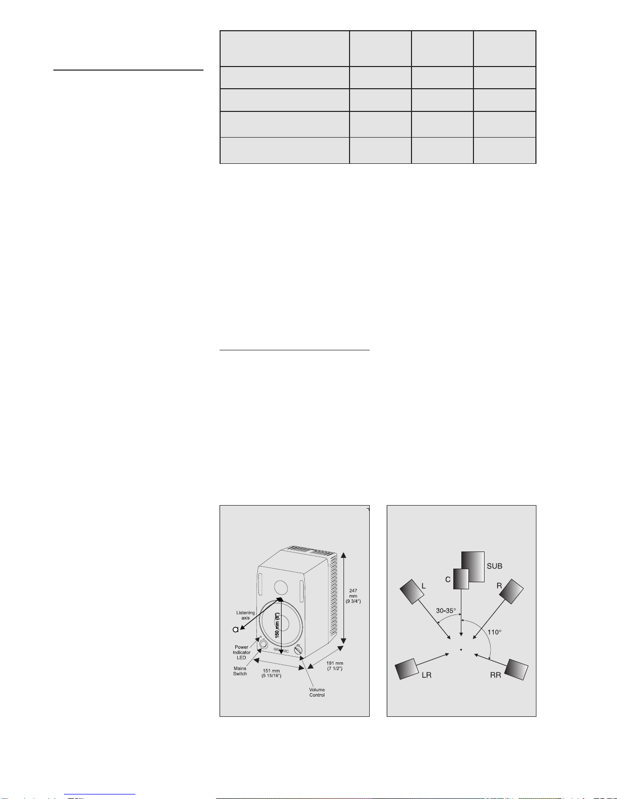
Figure 1. Suggested tone control settings for differing acoustic environments
Figure 2: HT205 outer dimensions, with the
reference axis between the bass and the
trebledrivers.
speaker enclosure. The bass and
trebleamplifiersbothproduce40 Wof
output power. The fast, low distortion
amplifiers are capable of driving a
stereo pair to peak output sound
pressure levels in excess of 110 dB at
1 m. The unit incorporates special
circuitryfordriveroverloadprotection.
Variable input sensitivity allows for
accuratelevelmatchingtothedecoder
or preamplifier.
2. Installation2. Installation
2. Installation2. Installation
2. Installation
Place the loudspeakers in their
required positions, taking note of the
lineof thelistening axis(see figure 2).
Point the speakers to the center of the
listening area. See chapter "Speaker
placement" for further details.
Before connecting, ensure that the
mains switch is off and the volume
control (see figure 2) fully counter-
clockwise. Check that the mains
voltageselectoriscorrectlyset. Audio
inputis made viaa10 kOhmbalanced
(XLR)orunbalanced (RCA)connector
(see fig. 4). If the signal source has
suitable balanced outputs, we
recommendtheusetheXLRconnector
andbalancedinterconnectcablesdue
totheirbetterresistancetointerference.
Once the connection has been made,
thespeakers areready to beswitched
on.
Setting the volume control.Setting the volume control.
Setting the volume control.Setting the volume control.
Setting the volume control.
The input sensitivity of the speakers
can be matched to the output of the
signalsource byadjusting thevolume
controlonthefrontpanel(seefigure2).
Setting the tone controlsSetting the tone controls
Setting the tone controlsSetting the tone controls
Setting the tone controls
The response of the system usually
has to be adjusted to match the
acousticenvironment. Theadjustment
is done by setting the tone control
switches on the rear panel. The tone
control has four switches, 'treble tilt'
(sw.1),'bassroll-off.'(sw.2) and'bass
Figure3: Suggestedspeaker placement
andalignmentina5.1-channelSurround
system.
noitisoPgnitnuoMrekaepS elberT
)1hctiwS(tliT
ssaB
sehctiwS(tliT
)4&3
ssaB
ffo-lloR
)2hctiwS(
esnopserciohcenatalFffOffOffO
moordepmadanignidnatseerFffOffOffO
moortnarebreveranignidnatseerFffO 3.wS(Bd2-
)FFO4.wS,NO ffO
tenibacanirorenrocanIffO 3.wS(Bd6-
)NO4dna ffO
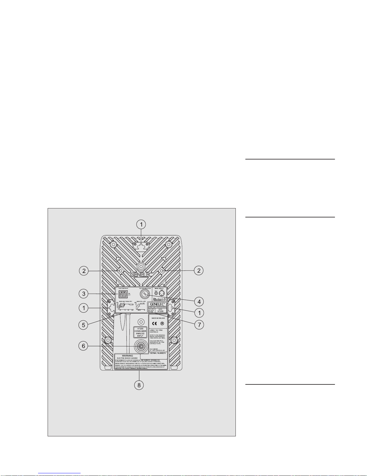
Figure4: HT205 rearpanel
tilt' (sw. 3 & 4).
"Treble tilt" attenuates the high
frequency response above 15 kHz by
two decibels. The "bass tilt" switches
provide three alternative attenuation
levels(-2,-4or-6dB)forlowfrequency
responsebelow150Hz. "Bassroll-off"
switch changes the bass roll-off
frequencyfrom65Hz to85Hz(-6dB).
Thefactorysetting is'ALLOFF'to give
a flat anechoic response. See Figure
1 for suggested tone control settings
in differing acoustic environments.
Figure5showstheeffectofthecontrols
ontheanechoicresponse.Alwaysstart
adjustment by setting all switches to
'OFF' position. Then set the switch if
needed to the 'ON' position to select
the response curve needed.
Speaker placement.Speaker placement.
Speaker placement.Speaker placement.
Speaker placement.
It is vital that the loudspeakers are
correctlypositionedintheroomasthis
greatly affects their performance. To
produce a true and accurate
soundstage the speakers must have
exactly similar frequency responses,
which is true in free field conditions.
In a room the frequency responses
change because the sound reflects
from the room’s boundaries. We
recommend that the speakers are
positioned at the same height and
also at the same distance from the
front and side walls. Then the
reflections,andthereforethechanges
to the frequency response, are as
similar as possible.
The DCW increases the directivity of
the loudspeaker; more sound is
directed on-axis and less to the sides.
Aim the loudspeakers towards the
center of the listening area to reduce
the effect of the room on the sound.
This is because more direct sound is
heardandreflectionsfromwallswhich
degrade the sound are minimised.
Mounting OptionsMounting Options
Mounting OptionsMounting Options
Mounting Options
Figure 4 shows the three possibilities
for mounting the HT205. On the base
of the speaker cabinet is a 3/8" UNC
threaded hole which can
accommodateastandardmicrophone
stand.
There is a provision for Omnimount®
size50bracket,whichcanbeattached
totwothreadedholesatthebackofthe
loudspeaker with two M6x10 mm
screws. There are also three keyhole
slots for hanging the speaker on the
wall horizontally or vertically on a 4
mm screw with a suitable wide head.
Enclosedisabagcontainingfourlarge,
and four small friction pads. It is
suggested that the larger pads are
used on the base of the HT205, and if
mountedhorizontally,thesmallerpads
should be used on the side. There are
recesses where the pads should be
stuck.
3. Maintenance3. Maintenance
3. Maintenance3. Maintenance
3. Maintenance
No user serviceable parts are to be
found within the amplifier unit. Any
maintenance or repair of the HT205
unit should only be undertaken by
qualified service personnel.
4. Safety Considerations4. Safety Considerations
4. Safety Considerations4. Safety Considerations
4. Safety Considerations
Servicing and adjustment should only
be performed by qualified service
personnel. The amplifier's rear panel
must not be opened, except by
qualified service personnel.
The speaker should not be placed in
an enclosed position as there will be
insufficientairflowtocooltheamplifier.
Do not use this product with an
unearthed mains cable as this may
compromise electrical safety.
Topreventfireorelectricshock,donot
expose the unit to water or moisture.
WARNING!WARNING!
WARNING!WARNING!
WARNING!
This equipment is capable of
producing sound pressure levels in
excess of 85 dB, which may cause
permanent hearing damage.
5. Guarantee5. Guarantee
5. Guarantee5. Guarantee
5. Guarantee
Thisproductisguaranteedforaperiod
oftwo years against faultsinmaterials
or workmanship. Refer to supplier for
full sales and guarantee terms.
1) Wallhangingpoints
2) ThreadedholesforOmnimount®
size 50 bracket
3) Tonecontrolswitches
4) Voltageselector
5) XLRsignalinput(balanced)
6) RCAsignalinput(unbalanced)
7) Mainsinput
8) 3/8" UNC thread at the base
of the speaker
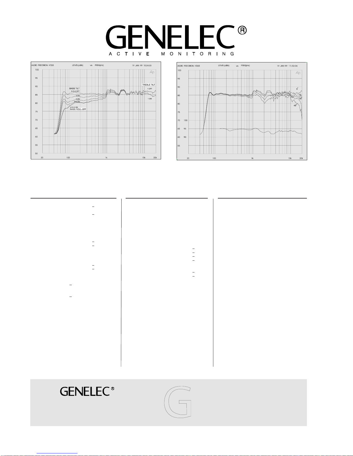
Figure 5: The curve above shows the effect of the 'treble tilt', 'bass tilt' and 'bass roll-
off' controls on the free field response. Figure 6: The curve group shows the horizontal directivity characteristics of HT205 in
its vertical configuration measured at 1m. The lower curve shows the systems power
response.
AMPLIFIERAMPLIFIER
AMPLIFIERAMPLIFIER
AMPLIFIER
SECTIONSECTION
SECTIONSECTION
SECTION
Bass amplifier output power with an 8 Ohm load:
40 W
Treble amplifier output power with an 8 Ohm load:
40 W
Long term output power is limited by driver unit
protection circuitry.
Amplifier system distortion at
nominal output: THD < 0.08%
SMPTE-IM < 0.08%
CCIF-IM < 0.08%
DIM 100 < 0.08%
Signal to Noise ratio, referred to full output:
Bass > 90 dB
Treble > 90 dB
Mains voltage: 100/200 or 115/230 V
Voltage operating range: ±10%
Power consumption: Idle 9 VA
Full output 80 VA
CROSSOVERCROSSOVER
CROSSOVERCROSSOVER
CROSSOVER
SECTIONSECTION
SECTIONSECTION
SECTION
Inputs: Input 1: XLR female, balanced 10 kOhm
Input 2: RCA female, unbalanced 10 kOhm
Volume control: Variable from Mute to -6 dBu for 100 dB
SPL output @ 1 m
Subsonic filter below 68 Hz :
18 dB/octave
Ultrasonic filter above 25 kHz:
12 dB/octave
Crossover frequency, Bass/Treble:
3.3 kHz
Crossover acoustical slopes:
24 - 32 dB/octave
Treble tilt control operating range:
0 to -2 dB @ 15 kHz
Bass roll-off control operating in a -6 dB step @ 85 Hz
Bass tilt control operating range in -2 dB steps:
0 to -6 dB @ 150 Hz
The 'CAL' position is with all tone controls set to 'off' and
the input sensitivity control to maximum (fully clockwise).
HT205SYSTEMHT205SYSTEM
HT205SYSTEMHT205SYSTEM
HT205SYSTEM
SPECIFICATIONSSPECIFICATIONS
SPECIFICATIONSSPECIFICATIONS
SPECIFICATIONS
Lower cutoff frequency, -3 dB: < 68 Hz
Upper cutoff frequency, -3 dB: > 20 kHz
Free field frequency response of system:70 Hz - 18 kHz
(± 2.5 dB)
Maximum short term sine wave acoustic output on axis
in half space, averaged from 100 Hz to 3 kHz:
@ 1 m > 100 dB SPL
@ 0.5 m > 106 dB SPL
Maximum long term RMS acoustic output in same
conditions with IEC weighted noise (limited by driver unit
protection circuit): @ 1m > 98 dB SPL
@ 0.5 m > 104 dB SPL
Maximum peak acoustic output per pair on top of
console, @ 1 m from the engineer with music material:
> 110 dB
Self generated noise level in free field @ 1m on axis:
< 10 dB (A-weighted)
Harmonic distortion at 85 dB SPL @ 1m on axis:
Freq: 75...150 Hz < 3%
> 150 Hz < 1%
Drivers: Bass 130 mm (5") cone
Treble 19 mm (3/4") metal dome
Both drivers are magnetically shielded
Weight: 5.7 kg (12.5 lb)
Dimensions: Height 247 mm (9 3/4")
Width 151 mm ( 5 15/16")
Depth 191 mm (7 1/2")
Genelec Document DRHT205001Genelec Document DRHT205001
Genelec Document DRHT205001Genelec Document DRHT205001
Genelec Document DRHT205001
COPYRIGHT GENELEC OY 1999COPYRIGHT GENELEC OY 1999
COPYRIGHT GENELEC OY 1999COPYRIGHT GENELEC OY 1999
COPYRIGHT GENELEC OY 1999
All data subject to change without prior noticeAll data subject to change without prior notice
All data subject to change without prior noticeAll data subject to change without prior notice
All data subject to change without prior notice
Note! All frequency response curves were measured in a
calibrated, 12 m cube, anechoic chamber at 1 m using
grade 1 measuring equipment. Input signal levels were set
at -20 dBu. The anechoic chamber error in the free field
response is less than 0.5 dB down to 60 Hz.
Genelec Oy, Olvitie 5
FIN - 74100 IISALMI, FINLAND
Phone: +358-17-83 881
Fax: + 358-17-812267
Email: [email protected]
Web: www.genelec.com
Genelec Inc., 7 Tech Circle
NATICK, MA 01760, U.S.A.
Phone: +1 508 652 0900
Fax: +1 508 652 0909
Email: [email protected]
Other Genelec Home Theater System manuals


