Genelec HT312A User manual
Genelec HT312A and HT315AHT312A and HT315A
Active Home Theater Systems
Operating Manual
HT312A and
HT315A
System
The Genelec HT312A and HT315A are
three-way active home theater loudspeaker
systems including drivers, multiple power
amplifiers and active crossovers. The sys-
tems are designed for room volumes up
to 175 m3 /6200 ft3(HT312A) or 250 m3 /
8800 ft3(HT315A) with maximum listening
distances up to 6.1 - 7.6 meters (20-25 ft).
They are designed to perform well both as
free-standing or flush mounted into the wall
structure.
The unique Directivity Control Waveguide™
(DCW™) Technology developed by Genelec
provides stable and extremely accurate imag-
ing and frequency balance even in difficult
acoustic environments. The fast, low distor-
tion amplifiers are capable of driving a stereo
system to peak output levels in excess of 124
dB SPL at 2 m (HT315A) or 123 dB SPL at
2 m (HT312A) with music material. Versatile
crossover controls allow for precise matching
of the loudspeaker system to different acous-
tic conditions.
Drivers and cabinet
construction
On the HT315A the low frequencies are
reproduced by an 385 mm (15”) bass driver
loaded with a 110 liter vented box. The
-3dB point is 33 Hz and the low frequency
response extends down to 29 Hz (-6 dB).The
HT312A features a 305 mm (12”) bass driver
in a 65 liter vented box with the -3 dB point at
35 Hz and -6 dB at 32 Hz.
Both models share the same midrange
and high frequency driver layout with a pro-
prietary 130 mm (5”) direct radiating cone
for the MF and a 25 mm (1”) metal dome for
the HF loaded by proprietary Directivity Con-
trol Waveguide. All drivers are magnetically
shielded.
Crossover filters
The active crossover network consists of
three parallel bandpass filters. The crosso-
ver frequencies are 410 Hz and 3.0 kHz on
the HT315A and 420 Hz and 3.2 kHz on the
HT312A. Bass, midrange and treble level
controls with 1 dB steps are included in the
crossover to obtain uniform frequency bal-
ance in different acoustic conditions. The low
frequency Tilt and Roll-Off controls both have
four 2 dB steps to allow refined low frequency
response tailoring. The crossover network is
driven by an active balanced input stage, fed
by a 3 pin XLR connector. Variable input sen-
sitivity allows for accurate level matching to
the signal source output.
Amplifiers
The bass, midrange and treble amplifiers
on the HT315A produce 400 W, 120 W and
120 W of short term power. The HT312A has
a 180 W amplifier for the low frequency driver
and 120 W amplifiers each for midrange and
treble drivers. The amplifiers are designed to
operate at very low THD and IM distortion
values and incorporate special circuitry for
driver overload protection and amplifier ther-
mal protection.
Installation
Each loudspeaker is supplied with an inte-
grated amplifier unit, a mains cable and an
operating manual. Once unpacked place the
loudspeaker in its required listening position,
taking note of the line of the acoustical axis
(see Figure 1).
Sufficient cooling for the amplifier must
be ensured. The minimum clearance for the
amplifier is 10 centimeters (4”) to any object.
The space adjacent to the amplifier must
either be ventilated or sufficiently large to
dissipate heat so that the ambient tempera-
ture does not rise above 35 degrees Celsius
(95°F). If the loudspeaker is flush mounted
into the wall structure, the amplifier can be
placed separately into an equipment rack
using an optional rack mount kit (see sec-
tions ‘Flush mounting’ and ‘Accessories’).
Before connecting up, ensure that the
mains switch is off (see Figure 2). Check that
the mains voltage selector is correctly set to
your local voltage. Audio input is made via a
Genelec HT312A and HT315A Active Home Theater Systems
EC Declaration of Conformity
This is to certify that the Genelec HT312A and HT315A
Active Home Theater Systems conform to the following
standards:
Safety:
EN / IEC 60065:1998 6th Edition
EMC:
EN 55020 : 2002 + A1 : 2003
EN 55013: (2001)
EN 61000-3-2 (2000)
EN 61000-3-3 (1995)
The product herewith complies with the requirements of The
Low Voltage Directive73/23/EEC, EMC Directive 89/336/
EEC and 93/68/EEC
Signed:
Ilpo Martikainen
Position: Managing Director
Date: 3-October-2005
10kOhm balanced XLR connector, but unbal-
anced leads may be used as long as pin 3 is
grounded to pin 1 of the XLR. Once connec-
tion has been made, the loudspeakers are
ready to be powered-up.
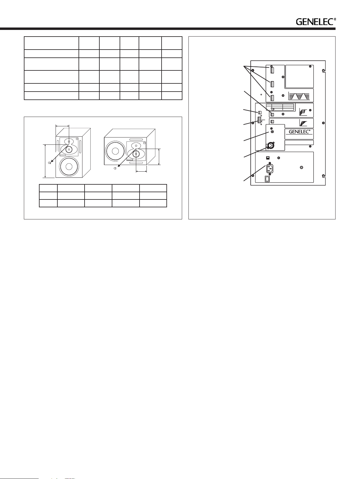
Setting the input sensitivity
Adjustment of the input sensitivity of each
loudspeaker can be made to match the output
of the mixing console or other source, by use
of the input sensitivity control on the rear
panel (see Figure 2). A small screwdriver is
needed for the adjustment. The manufacturer
default setting for this control is -6 dBu (fully
clockwise) which gives an SPL of 100 dB
@1m with -6 dBu input level. To get the full
output level of 120 dB SPL from the HT315A
an input level of +14 dBu is needed at this
setting. Respectively, the full output level of
the HT312A is reached at an input level of
+10 dBu.
Autostart and remote control
The HT312A and HT315A are equipped with
an “Autostart” function, which automatically
turns the amplifier to “standby” mode if an
input signal has not been detected for approx-
imately thirty minutes, and back to “on” mode
when the signal returns. The function can be
deactivated by turning the “AUTOSTART” dip
switch to “OFF”. A two-colour LED on the
amplifier panel indicates the amplifier status:
green for “on” and yellow for “standby”.
The amplifier mode can also be switched
by a remote control unit connected to the
respective inputs on the amplifier. Two pairs
of connectors are provided, 1 and 2 for a 12
V DC type remote control, and 3 and 4 for
an external switch or relay type control. Do
not connect two remote controls to the loud-
speakerat the same time. Activate the func-
tion by turning the "REMOTE CONTROL" dip
switch on the amplifier panel to "ON". Note
that the remote control function overrides the
“autostart” dip switch function.
Setting the tone controls
The acoustic response of the system may
also have to be adjusted to match the acoustic
environment. The adjustment is done by set-
ting the five tone control switch groups ‘bass
tilt’, ‘bass roll-off’, ‘bass level’, ‘mid level’ and
‘treble level’ on the rear panel of the amplifier.
The manufacturer’s default settings for these
controls are ‘All Off’ to give a flat anechoic
response. See Table 1 for suggested tone
control settings in differing acoustic environ-
ments. Figures 7 and 8 show the effect of the
controls on the anechoic response. Always
start adjustment by setting all switches to
the ‘OFF’ position. Then set only one switch
per group to the ‘ON’ position to select the
response curve required. If more than one
switch is set to ‘ON’ (within one switch group)
the attenuation value is no longer accurate.
Vertical / horizontal mounting
The loudspeakers are delivered either for
vertical or horizontal mounting. In the hori-
zontal mounting position the bass drivers
should point inwards to obtain better low
frequency coupling. If the loudspeaker posi-
tioning needs to be changed, the DCW plate
can be rotated so that the midrange driver
remains always located at the bottom of the
DCW. Remove the four corner screws of the
DCW and pull the plate carefully out without
stressing the wires and the gasket. Rotate
the plate 90 degrees in the appropriate direc-
tion and remount the screws.
Flush mounting
The HT312A and HT315A can be used flush
mounted into the wall structure, which offers
some acoustical benefits. No cabinet edge
diffraction will occur, resulting in an improved
response, especially at midrange frequen-
cies. Low frequency reflections from the wall
behind the loudspeaker can be avoided,
which improves the low frequency response
and efficiency and allows the loudspeaker
to work in half space conditions. In terms of
installation and orientation, the loudspeaker’s
acoustical axis (See Figure 1.) should also
point directly to the the reference listening
position. The loudspeakers should be verti-
Loudspeaker mounting
position
Bass
roll-off
Bass
tilt
Bass
level
Midrange
level
Treble
level
Free anechoic response None None None None None
Free standing in a
damped room
None -2 dB None None None
Free standing in a
reverberant room
None -2 dB -2 dB None None
In a corner -2 dB -2 dB -2 dB None None
Flush mounted None None -4 dB None None
Table 1. Suggested tone control settings for different acoustic environments
H1 mm (in) W1 mm (in) H2 mm (in) W2 mm (in)
HT312A 540 (21 1/4") 200 (7 7/8") 230 (9 1/16") 170 (6 11/16")
HT315A 650 (25 5/8") 240 (9 1/2") 282 (11 1/8") 202 (7 15/16")
W1
H1
> 1m
W2
H2
ACOUSTICAL
AXIS
> 1m
Figure 1. Location of the acoustic axis Figure 2. Amplifier panel layout of the HT312A.
-1
-2
-3
-4 dB
-5
-6
MUTE
SERIAL
NUMBER
WARNING
NEVER OPERATE THIS EQUIPMENT WITHOUT A PROPER
EARTHED MAINS CONNECTION.
IT IS FORBIDDEN TO UNDO ANY SCREWS ON THIS EQUIPMENT.
SERVICING AND ADJUSTMENT MUST ONLY BE CARRIED OUT
BY QUALIFIED SERVICE PERSONNEL.
DO NOT EXPOSE TO WATER OR MOISTURE.
THIS EQUIPMENT IS CAPABLE OF PRODUCING SOUND
PRESSURE LEVELS IN EXCESS OF 85dB WHICH MAY CAUSE
PERMANENT HEARING DAMAGE.
ENSURE THAT THE CORRECT VOLTAGEIS SELECTED BEFORE
CONNECTING TO THE MAINS SUPPLY.
ELECTRIC SHOCK HAZARD!
MAINS INPUT
50 / 60 Hz
300 Watts
115 / 230 V
ON
˜
PIN 1 = GROUND
PIN 2 = + INPUT
PIN 3 = - INPUT
MAINS
VOLTAGE
SELECTOR
2
3
20Hz 100Hz
20Hz 250Hz
-8
INPUT SENSITIVITY
REQUIRED FOR
100dB SPL@1m.
REFER TO
OPERATING MANUAL
FOR MAXIMUM SPL.
SIGNAL INPUT
INPUT SENSITIVITY
-6
1
dBu
+6
+2
+4 -4
-2
0
BASS
TILT
BASS
ROLL-OFF
-2
-4 dB
-6
-8
OFF ON
-2
-4 dB
-6
-8
OFF ON
-2
0
-6
-4
ALLOFF
dB
-2
-8
-6
-4
0
dB
ALLOFF
CAL POSITION
ALL TONE CONTROLS : OFF
INPUT SENSITIVITY : -6dBu
20Hz 400Hz 3kHz 20kHz
FOR A FLAT FREE FIELD RESPONSE SET ALL
TONE CONTROLS TO OFF.
FOR ACCURATE OPERATION ONLY ONE
SWITCH IN EACH TONE CONTROL GROUP
SHOULD BE ON AT A TIME.
REFER TO THE OPERATING MANUAL FOR
SUGGESTED TONE CONTROL SETTINGS.
BASS
LEVEL
-1
-2
-3
-4 dB
-5
-6
MUTE
OFF ON
0
-1
-2
-3
-4
-5
-6
dB
BASS
TREBLE
LEVEL
MID
LEVEL
OFF ON
-1
-2
-3
-4 dB
-5
-6
MUTE
OFF ON
TREBLEMID
LEVEL CONTROLS
USING THE TONE CONTROLS
MADE IN FINLAND
www.genelec.com
MAGNETICALLYSHIELDED
GND
EXTERNAL
SWITCH
OR RELAY
12 V DC
REMOTE
2
3
4
1+
REMOTECTRL
AUTOSTART
POWER LED
STANDBYLED
REMOTE
CONTROL
OFF ON
DO NOT USE BOTH
REMOTE CONTROL
TYPES ATTHE
SAME TIME.
SWITCH THE REMOTE
CONTROL DIP SWITCH
ON WHEN USING
REMOTE CONTROL.
REMOTE CONTROL
OVERRIDES
AUTOSTARTFUNCTION.
AUTOSTARTSETS
THE AMPLIFIER TO
STANDBYMODE
WHEN THERE
IS NO SIGNAL.
CONNECTOR
PIN NO.
3 EXTERNAL SWITCH
4 OR RELAY
REMOTE CONTROL
TYPE
1 +
2 GND 12 V DC REMOTE PIN 1 HIGH: ON
PIN 1 LOW: STANDBY
AMPLIFIER MODE
CONTACTCLOSED: ON
CONTACTOPEN: STANDBY
HT312A ACTIVE HOME THEATER SYSTEM
ON
TREBLE,MIDRANGE
AND BASS LEVEL
SWITCHES
BASS TILT AND
ROLL-OFF
SWITCHES
INPUT
SENSITIVITY
ADJUSTMENT
SIGNAL INPUT
CONNECTOR
MAINS VOLTAGE
SELECTOR, MAINS
CONNECTOR
AND SWITCH
REMOTE CONTROL
AND INDICATOR LED
SWITCHES
REMOTE CONTROL
CONNECTORS
cally aimed so that the acoustical axis of the
loudspeakers meet around ear height at the
reference listening position. In the horizontal
plane the loudspeaker should be positioned
according to the standard stereophonic (60
degrees between left-right channels) or mul-
tichannel (ITU-R BS.775-1) placement rec-
ommendation.
The ceiling, side walls and especially the
rear wall should be acoustically absorbent at
low frequencies. The wall in which the loud-
speakers are mounted should have a high
acoustical mass to properly implement a low
frequency radiation condition into half space
and be angled so that the loudspeakers are
correctly aimed. However, the loudspeak-
ers should not be mounted too high as this
increases the required vertical tilt of the loud-
speaker (maximum tilt angle < 20 degrees)
and reduces the optimum listening area. Great
care should be taken over how the loudspeaker
is mounted into the wall. Note the following:
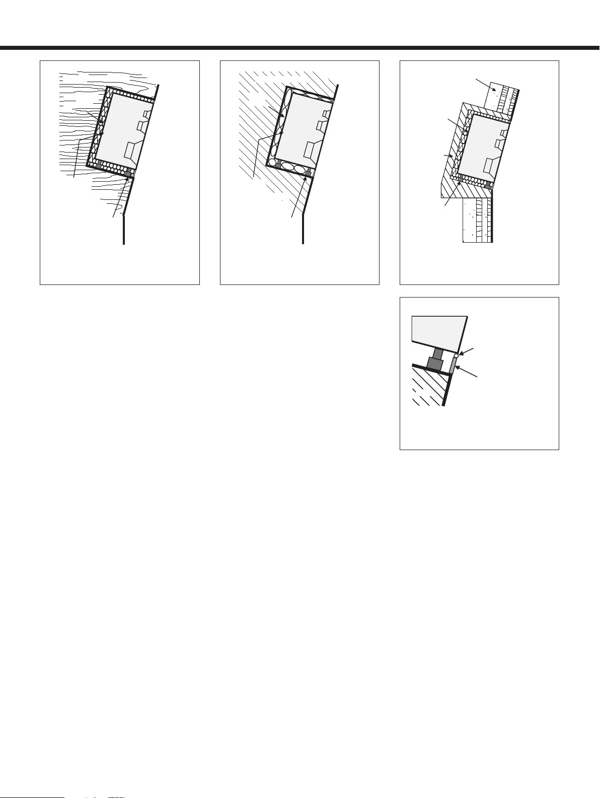
A space 50 to 100 mm (2 to 4”) wide can
be left around the loudspeaker. Cover the
space around the loudspeaker with a facing
panel that should be fixed to the wall. Leave
a gap of about 5 to 10 mm (¼ to ½”) between
the loudspeaker and the panel. Fill this gap
with a soft rubber gasket to allow for possible
cabinet movement (see Figure 6).
Ensure that the loudspeaker cables can
reach the rear of the loudspeaker cabinets.
Regardless of the type of front wall con-
struction the loudspeaker cabinet should be
mounted on vibration isolators, with a resonant
frequency between 2 to 8 Hz, to prevent vibra-
tions from being transmitted to the wall and
impairing the low frequency performance.
If a heavy wooden front wall construction
is used, the space around the cabinet should
be filled with absorbent mineral wool or foam
plastic. The wooden wall structure must be
heavily braced to achieve sufficiently high
mass and rigidity (see Figure 3).
In a solid wall (e.g. concrete) structure, the
space around the cabinet should be filled
with either absorbent mineral wool or sand
bags (see Figure 4).
The wall can also be constructed of a com-
bination of materials to achieve high acousti-
cal structural mass that will disable low fre-
quency sound propagation and provide high
LF sound isolation (see Figure 5). Acoustic
consultants will be able to provide details and
design these structures.
Ensure that the cabinet is flush with the
surface of the wall. Discontinuities in the loud-
speaker mounting wall will cause diffraction,
which leads to inferior frequency response
and imaging. So, if a decorative cloth frame
is used to cover the wall, make sure that the
edges adjacent to the loudspeaker are less
than 20 mm (3/4”) deep. The cloth must be very
thin Tricot or an acoustically transparent mate-
rial otherwise the high frequency response of
the system will be adversely affected. Genelec
approved cloth grilles are available.
Mode indicator LED
The loudspeaker is provided with a three-
colour indicator LED on the DCW™ panel.
When the LED is green, it indicates that the
loudspeaker is ready for use. Standby mode
is indicated by yellow colour. Amplifier clip-
ping is indicated by a blinking red light and
thermal protection mode by a constant red
light. If clipping is indicated reduce the signal
level so that the LED stops blinking. If the
red LED stays on constantly, switch off the
loudspeaker and the audio source and let the
amplifier cool down. Check that the ventila-
tion around the amplifier is not blocked. There
should be a clearance of more than 100 mm
(4”) between the amplifier face panel and any
solid surface at the back. If the red light does
not come off, contact authorised Genelec
service.
The LED can be deactivated if you find it
disturbing in a darkened room by turning both
the "POWER LED" and "STANDBY LED"
switches on the amplifier panel to "OFF".
Maintenance
No user serviceable parts are to be found
within the amplifier unit. Any maintenance or
repair should only be undertaken by quali-
fied service personnel. Ensure that if fuse
replacement is required, only fuses of the
same voltage and current rating are used.
Remember to disconnect the power supply
by removal of the mains cable, before fuse
replacement.
Figure 3: Flush mounting the loudspeaker in
a wall constructed of wood
Figure 4: Flush mounting the loudspeaker in
a wall constructed of concrete
Figure 5: Flush mounting the loudspeaker
in a wall constructed of a combination of
materials.
HEAVY WOODEN WALL
ABSORBING
MATERIAL
VIBRATION
ISOLATORS
f ~ 2-8 Hz
AMPLIFIER
REMOVED
FROM ENCLOSURE
CONCRETE WALL
SAND
BAGS
VIBRATION
ISOLATORS
f ~ 2-8 Hz
AMPLIFIER
REMOVED
FROM ENCLOSURE
CONCRETE
STRUCTURE
MULTI-LAYERED WALL
(WOOD, CONCRETE,
BRICKS)
VIBRATION
ISOLATORS
f ~ 2-8 Hz
AMPLIFIER
REMOVED
FROM
ENCLOSURE
FACING PANEL
FIXED TO THE WALL
(50-100 mm / 2-4")
RUBBER GASKET
(5-10 mm / ¼-½")
SPEAKER
WALL
Figure 6: Covering the gap between the
wall and the loudspeaker cabinet.

Figure 7: The curves above show the effect of the ‘bass’, ‘mid’ and
‘treble’ level controls, and the ‘bass tilt’ and ‘bass roll-off’ controls
on the free field response of the HT312A, measured at 2 m.
Safety considerations
Although the HT312A and HT315A loud-
speakers have been designed in accordance
with international safety standards, to ensure
safe operation and to maintain the instrument
under safe operating conditions, the following
warnings and cautions must be observed:
1. Servicing and adjustment must only
be performed by qualified service
personnel. The amplifier must not be
opened.
2. Do not use the loudspeakers with an
unearthed mains cable or unearthed
mains connection as this may lead to
personal injury.
3. These loudspeakers are capable of
producing sound pressure levels in
excess of 85 dB, which may cause
permanent hearing damage.
4. Free flow of air around the amplifier is
necessary to maintain sufficient cooling.
Do not obstruct airflow around the
amplifier
5. To prevent fire or electric shock, do not
expose the unit to water or moisture. Do
not place any objects filled with liquid,
such as vases on or near the
loudspeaker or the amplifier.
6. Note that the amplifier is not completely
disconnected from the AC mains
service unless the mains cable
is removed from the amplifier or the
mains outlet.
Guarantee
This product is supplied with one year guar-
antee against manufacturing faults or defects
80
85
90
20
20k
50
100 200 500
1k 2k
5k
10k
dBr
Hz
80
85
90
80
85
90
BASS LEVEL
BASS ROLL-OFF MIDRANGE LEVEL
BASS TILT
TREBLE LEVEL
AUDIO PRECISION 1038BANEC vs 16 APR 02LEVEL(dBr) FREQ(Hz)
BASS TILT
BASS LEVEL TREBLE LEVEL
BASS ROLL-OFF MIDRANGE LEVEL
80
85
90
20
20k
50
100 200 500
1k 2k
5k
10k
dBr
Hz
80
85
90
80
85
90
AUDIO PRECISION 1037CANEC vs 04 OCT 02LEVEL(dBr) FREQ(Hz)
0
15
30
45
65
70
75
80
85
90
95
20
20k
50
100 200 500
1k 2k
5k
10k
dBr
Hz
85
90
95
100
AUDIO PRECISION 1037CANEC vs 04 0CT 02LEVEL(dBr) FREQ(Hz)
65
70
75
80
85
90
95
20
20k
50
100 200 500
1k 2k
5k
10k
0°
30°
15°
45°
dBr
Hz
85
90
95
100
AUDIO PRECISION 1038BANEC vs 16 APR 02LEVEL(dBr) FREQ(Hz)
Figure 9: The upper curve group shows the horizontal directivity
characteristics of the HT312A in its vertical configuration
measured at 2 m. The lower curve is a 1/6 octave power
response measurement, derived from 144 individual directivity
measurements.
that might alter its performance. Refer to sup-
plier for full sales and guarantee terms.
HT312A Accessories
Order code
Handles 1001-406*
Protective grille 1037-409
Rack adapter 1037-412
* Factory installed option only
HT315A Accessories
Order code
Handles 1001-406*
Protective grille 1038-409
Rack adapter HT315-400
* Factory installed option only
Figure 8: The curves above show the effect of the ‘bass’, ‘mid’ and
‘treble’ level controls, and the ‘bass tilt’ and ‘bass roll-off’ controls
on the free field response of the HT315A, measured at 2 m.
Figure 10: The upper curve group shows the horizontal directivity
characteristics of the HT315A in its vertical configuration
measured at 2 m. The lower curve is a 1/6 octave power
response measurement, derived from 144 individual directivity
measurements.
HT312A and HT315A Operating Manual
Genelec Document D0067R001 Copyright Genelec Oy 10.2005. All data subject to change without prior notice www.genelec.com
International enquiries:
Genelec, Olvitie 5
FIN-74100, Iisalmi, Finland
Phone +358 17 83881
Fax +358 17 812 267
Email [email protected]
In the U.S. please contact:
Genelec, Inc., 7 Tech Circle
Natick, MA 01760, USA
Phone +1 508 652 0900
Fax +1 508 652 0909
Email [email protected]
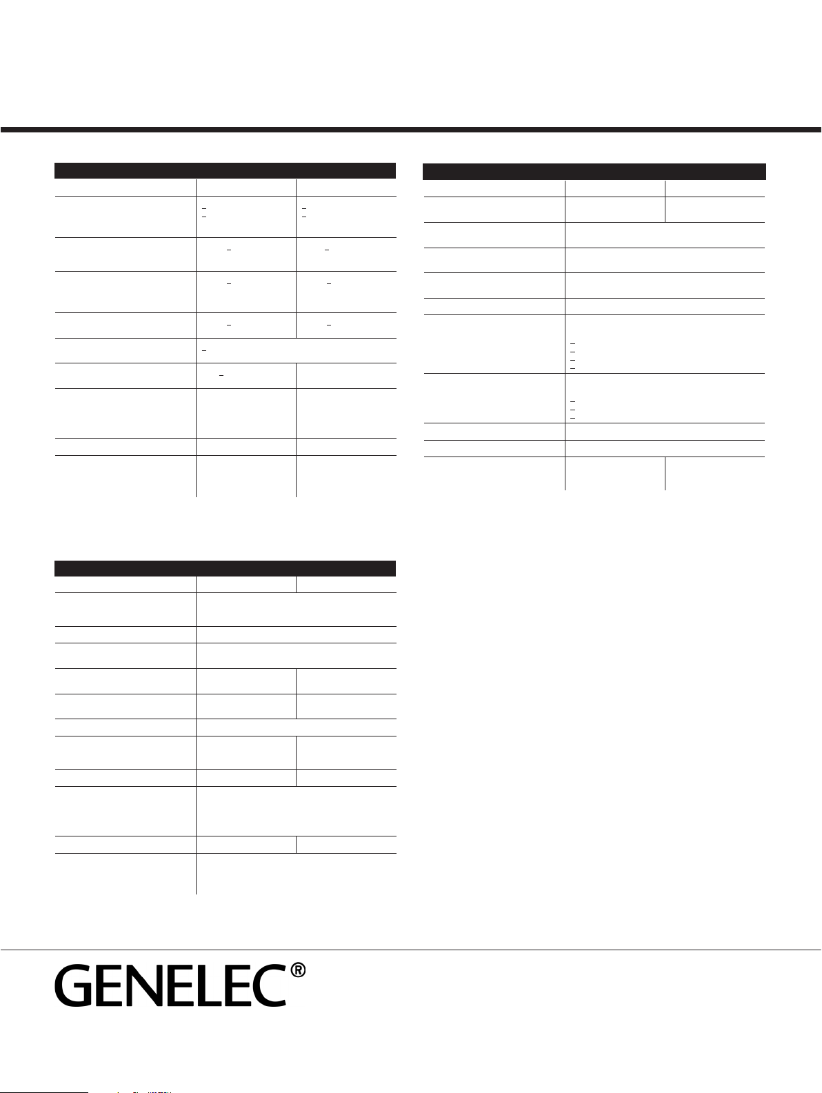
system specifications
Ht312a Ht315a
Lower cut-off frequency, -3 dB
Upper cut-off frequency, -3 dB
Free field frequency response
of system
<35 Hz
>22 kHz
37 Hz - 21 kHz (±2.5 dB)
<33 Hz
>20 kHz
35 Hz - 20 kHz (±2.5 dB)
Maximum short term sine wave
acoustic output on axis in half space,
averaged from 100 Hz to 3 kHz
@ 1 m >116 dB SPL @1 m >120 dB SPL
Maximum long term RMS acoustic
output in same conditions with IEC-
weighted noise (limited by driver unit
protection circuit)
@ 1 m >107 dB SPL @ 1 m >116 dB SPL
Maximum peak acoustic output per
pair above console with music materia
@ 2 m >123 dB @ 2 m >124 dB
Self generated noise level in free field
@ 2 m on axis
<15 dB (A weighted)
Harmonic distortion at 95 dB SPL at
1m on axis:
freq. <100 Hz <1%
freq. >100 Hz <0.5%
freq. 50...100 Hz <1%
freq. >100 Hz <0.5%
Drivers
Bass
Midrange
Treble
All drivers are magnetically shielded
305 mm (12") cone
130 mm (5") cone
25 mm (1") metal dome
385 mm (15") cone
130 mm (5") cone
25 mm (1") metal dome
Weight 37 kg (82 lb) 60 kg (130 lb)
Dimensions
Height
Width
Depth
680 mm (26 3/4")
400 mm (15 3/4")
380 mm (14 15/16")
810 mm (31 7/8")
480 mm (18 7/8")
420 mm (16 9/16")
Ht312a Ht315a
Input connector XLR female pin 1 gnd
pin 2 +
pin 3 -
Input impedance 10 kOhm
Input level for 100 dB SPL
output @1m
variable from +6 to -6 dBu
Input level for maximum short term
output
variable from +22 to +10
dBu for 116 dB SPL @1m
variable from +26 to +14
dBu for 120 dB SPL @1m
Subsonic filter 18 dB/octave
below 35 Hz
18 dB/octave
below 33 Hz
Ultrasonic filter 12 dB/octave above 25 kHz
Crossover frequency
Bass/Mid
Mid/Treble
420 Hz
3.2 kHz
410 Hz
3 kHz
Crossover acoustical slopes 18 - 24 dB/octave 24 - 32 dB/octave
Crossover level control operating
range in 1 dB steps
Bass
Mid
Treble
from 0 to -6 dB
from 0 to -6 dB
from 0 to -6 dB
Bass roll-off control in 2 dB steps from 0 to -8 dB @35 Hz from 0 to -8 dB @33 Hz
Bass tilt control in 2 dB steps from 0 to -8 dB @80 Hz
The 'CAL' position is with all tone controls set to 'off'
and input sensitivity control to maximum.
Ht312a Ht315a
Bass amplifier short term output
power
180 W (4 Ohm load) 400 W (8 Ohm load)
Midrange amplifier short term output
power with an 8 Ohm load
120 W
Treble amplifier short term output
power with an 8 Ohm load
120 W
Long term output power is limited by driver unit protec-
tion circuitry.
Slew rate 80V/µs
Amplifier system distortion at nominal
output
THD
SMPTE-IM
CCIF-IM
DIM 100
<0.05%
<0.05%
<0.05%
<0.05%
Signal to Noise ratio, referred to full
output
Bass
Midrange
Treble
>100 dB
>100 dB
>100 dB
Mains voltage 100/200V or 115/230V
Voltage operating range nominal ±10%
Power consumption
Idle
Full output
50 W
300 W
60 W
500 W
amplifier section
crossover section
In Sweden please contact
Genelec Sverige
Ellipsvägen 10B
P.O. Box 5521, S-141 05 Huddinge
Phone +46 8 449 5220
Fax +46 8 708 7071
Email [email protected]
In China please contact:
Beijing Genelec Audio Co. Ltd.
Jianwai SOHO, Tower 12, Room 2306
39 East 3rd Ring Road
Chaoyang District
Beijing 100022, China
Phone +86 0 5869 7915, Fax +86 10 5869 7914
This manual suits for next models
1
Table of contents
Other Genelec Home Theater System manuals


