Gentex SSPKCLP series User manual

SSPKCLP & SSPK24CLP SERIES
ANSI/UL 1480 AND/ R ANSI/UL 1971 C MPLIANT
SSPKR24 SERIES
ANSI/UL 1480 AND ANSI/UL 1638 C MPLIANT
UNIVERSAL M UNT L W PR FILE SPEAKER AND
CEILING M UNT L W PR FILE SPEAKER/STR BE
CAU ION: Strobe light
must be installed within
16 feet of the pillow when
used in a sleeping area.
550-0490
Page 1
MODELS
SSPKCLP*................ LOW PROFILE CEILING OR WALL MOUNT SPEAKER WIT OUT STROBE
SSPK24CLP*............ LOW PROFILE CEILING MOUNT SPEAKER WIT SELECTABLE STROBE
SSPKR24C*.............. LOW PROFILE CEILING MOUNT SPEAKER WIT SELECTABLE STROBE AND RED LENS
*Includes one or more of the following designators, P (plain), R (red) or W (white).
I. IN RODUC ION
The Gentex SSPKCLP/SSPK24CLP/SSPKR24C is a high quality speaker and speaker/strobe ANSI/UL Listed for fire protective signaling systems. The high intensity strobe
utilizes a Xenon flash tube which generates a high-intensity light visible from all sides. The SSPK24CLP strobe is ANSI/UL Listed in compliance with ANSI/UL 1971, Signaling
Appliances for the earing Impaired. The SSPKR24 strobe is ANSI/UL Listed in compliance with ANSI/UL 1638, Visual Signaling Appliances - Private Mode Emergency and
General Signaling.
II. PRODUC INFORMA ION
The SSPKCLP/SSPK24CLP/SSPKR24 Series speaker and speaker/strobe offer a choice of field selectable power taps, 1/8, 1/4, 1/2, 1, 2 and 4 Watts for either 25v or 70.7v
audio amplifiers. The SSPK24CLP speaker/strobe offers the option of a high intensity strobe which complies with ANSI/UL 1971. The SSPKR24 speaker/strobe offers the
option of a high intensity strobe which complies with ANSI/UL 1638.The frequency range of the speakers is 400-4000 z. All devices are suitable for line supervision.
Speaker includes DC blocking capacitor which allows for supervision voltage of either polarity.
III. LOCA ION
This appliance is intended for use in Fire Alarm Systems and is to be installed in accordance with this installation manual, the recommendation of the local authorities having
jurisdiction, and other NFPA Standards that provide standards on notification appliances for protective signaling systems. The Gentex SSPKCLP/SSPK24CLP/SSPKR24
Series is intended for indoor installation only. This appliance is not listed for outdoor or drip proof applications.
**Effective Intensity Requirements for Sleeping Area
Visible Notification Appliance
Distance from Ceiling to op of Lens Intensity
greater than or equal to 24" (610mm) 110 Cd
less than 24" (610mm) 177 Cd
SSPK24CLP PRODUCT INFORMATION
Room Spacing for Ceiling-Mounted Visible Appliances per NFPA 72, 2010 Edition
Minimum Required Light Output (Effective Intensity, Cd; One Light)
Maximum Room Size Maximum Ceiling eight
Meters Feet 10 Foot Ceiling 20 Foot Ceiling 30 Foot Ceiling
6.10 x 6.10 20 x 20 15 30 55
9.14 x 9.14 30 x 30 30 45 75
13.4 x 13.4 44 x 44 75 75 NA
15.2 x 15.2 50 x 50 95 95 95

550-0490
Page 2
SSPKR24C PRODUCT INFORMATION
Model Color Lens
SSPKR24C Red
SYS EM CONSIDERA IONS
1. To select the proper wattage input for the speaker, move the jumper to the appropriate pin.
2. Always maintain electrical isolation between speaker and strobe wiring on combination units.
3. Do not exceed 130% of rated speaker voltage. If excessive distortion is heard, check amplifier for signal clipping. If clipping exists, reduce either amplifier input or gain.
4. Four screws are provided, two for securing speaker to the back box and two for aesthetics. The two non-functional screws will be held in place by the pressure fit of the
faceplate.
IV. ELEC RICAL SPECIFICA IONS
NOTICE: DC VOLTAGE RANGE LIMITS: 16-33V. FWR VOLTAGE RANGE LIMITS: 16-33V. T IS PRODUCT WAS ONLY TESTED TO T E STATED VOLTAGE RANGE(S);
DO NOT APPLY 80% AND 110% OF T IS RANGE FOR SYSTEM OPERATION.
CLEAR Lens Strobe Current Ratings
Use with SSPK24CLP Products
Candela
Regulated 24VDC
Max. Operating
Current (mA)
Regulated 24VFWR
Max. Operating
Current (mA)
15 120 190
30 120 191
75 200 277
95 220 298
115 290 418
Field Selectable Power ap Selection
Voltage 1/8 Watt 1/4 Watt 1/2 Watt 1 Watt 2 Watt 4 Watt
25 Volts 74.6 dBA @ 10ft. 77.7 dBA @ 10ft. 80.5 dBA @ 10ft. 83.1 dBA @ 10ft. 85.6 dBA @ 10ft. 87.9 dBA @ 10ft.
70.7 Volts 73.7 dBA @ 10ft. 76.7 dBA @ 10ft. 79.6 dBA @ 10ft. 82.5 dBA @ 10ft. 85.4 dBA @ 10ft. 87.9 dBA @ 10ft.
RED Lens Strobe Current Ratings
Use with SSPKR24C Products
Candela
Regulated 24VDC
Max. Operating
Current (mA)
Regulated 24VFWR
Max. Operating
Current (mA)
15 128 220
30 128 220
75 225 306
95 235 402
115 341 444
he visual signal must be in the direct viewing area of the occupant in order to be seen.
Strobe light can not be seen when objects such as doors, furniture or walls block strobe light.
NOTICE: VISUAL SIGNALS FOR T E EARING IMPAIRED ARE ONLY ONE MET OD OF ALERTING T E EARING IMPAIRED. VISUAL SIGNALS MAY NOT BE T E
PREFERRED MET OD FOR NOTIFYING ALL EARING IMPAIRED INDIVIDUALS.
NOTICE: T E STROBE LIG T MUST BE SEEN BY T E SLEEPING PERSON. IF T E PERSON AS EAD TURNED OR OT ERWISE UNABLE TO BE ALERTED BY
VISUAL, T E STROBE WILL NOT BE EFFECTIVE.
Visual signal should NEVER be relied upon as the primary fire alert for the hearing impaired under these common sense conditions:
a. Sleeping face down on the bedding or pillow
b. Use of sleep medications of any kind
c. Use of alcoholic beverages or recreational drugs
d. Use of eye shades
e. If there are tendencies of deep sleep conditions
f. If a fire cuts power to AC circuits, the visual signal will not operate
g. If person is not within line of sight of visual signals
Under these and other similar common situations an alternate fire alert method such as a non-hearing impaired attendant is needed. he visual signal only
increases the chance of being alerted to the presence of fire. No system of this type can fully protect the hearing impaired in case of fire.
CAU ION
W EN INSTALLING, ROUTE FIELD WIRING AWAY FROM S ARP
PROJECTIONS, CORNERS AND INTERNAL COMPONENTS.

550-0490
Page 3
V. MOUN ING ROUGH-IN BOX AND RUN WIRING
MOUN ING - SPEAKER
O GBLP BACK BOX
WALL OR CEILING MOUN
MOUN ING - SPEAKER/S ROBE
o 4” Square x 2 1/8” Deep
ME ALLIC BACK BOX - CEILING MOUN
SSPKCLP FIELD SELEC ABLE CANDELA SELEC OR
Adjust intensity by inserting small flat blade
screwdriver to turn dial. Displayed number will
indicate selected candela.
NOTICE: FIELD SELECTABLE OPTIONS OF 15, 30,
75, 95 AND 115 CANDELA.
Adjust power taps using
needle nose pliers.
NOTICE: DO NOT USE LOOPED
WIRE UNDER TER INALS.
BREAK WIRE RUN TO PROVIDE
SUPERVISION OF CONNECTION.
PANEL VOLTAGE - DEVICE INI U VOLTAGE
TOTAL CURRENT DRAW
* INCLUDES WIRE TO AND FRO APPLIANCE.
ASSU ES ALL APPLIANCES ARE AT THE END OF WIRE RUN (WORST CASE).
CAUTI N: APPLIES ONLY TO REGULATED SUPPLIES.
*MAX. WIRE DISTANCE (IN FEET) = X WIRE CONDUCTIVITY (STR BE NLY)
NOTICE: ALL STROBES ARE DESIGNED TO FLAS AS SPECIFIED WIT CONTINUOUS APPLIED VOLTAGE. T IS APPLIANCE IS NOT RECOMMENDED FOR USE ON CODED OR
PULSING SIGNALING CIRCUITS. OWEVER, USE OF T E AVSM CONTROL MODULE IS PERMITTED TO SYNC RONIZE T E STROBE.
NOTICE: REFERENCE AVSM CONTROL MODULE MANUAL (550-0284, DATED 2-1-03) FOR SYNC RONIZATION MODULE WIRING DIAGRAMS. AVSM MANUAL CAN BE OBTAINED AT
TTP://WWW.GENTEX.COM OR CALL GENTEX CORPORATION AT 1-800-436-8391.

T IS APPLIANCE WILL NOT OPERATE WIT OUT ELECTRICAL POWER. AS FIRES FREQUENTLY CAUSE POWER INTERRUPTIONS,
GENTEX SUGGESTS YOU DISCUSS FURT ER SAFEGUARDS WIT YOUR LOCAL FIRE PROTECTION SPECIALIST.
VI. O RE URN AN APPLIANCE
Should you experience problems with your appliance, proceed as follows:
1. Turn off electrical power to the auxiliary alarm circuit.
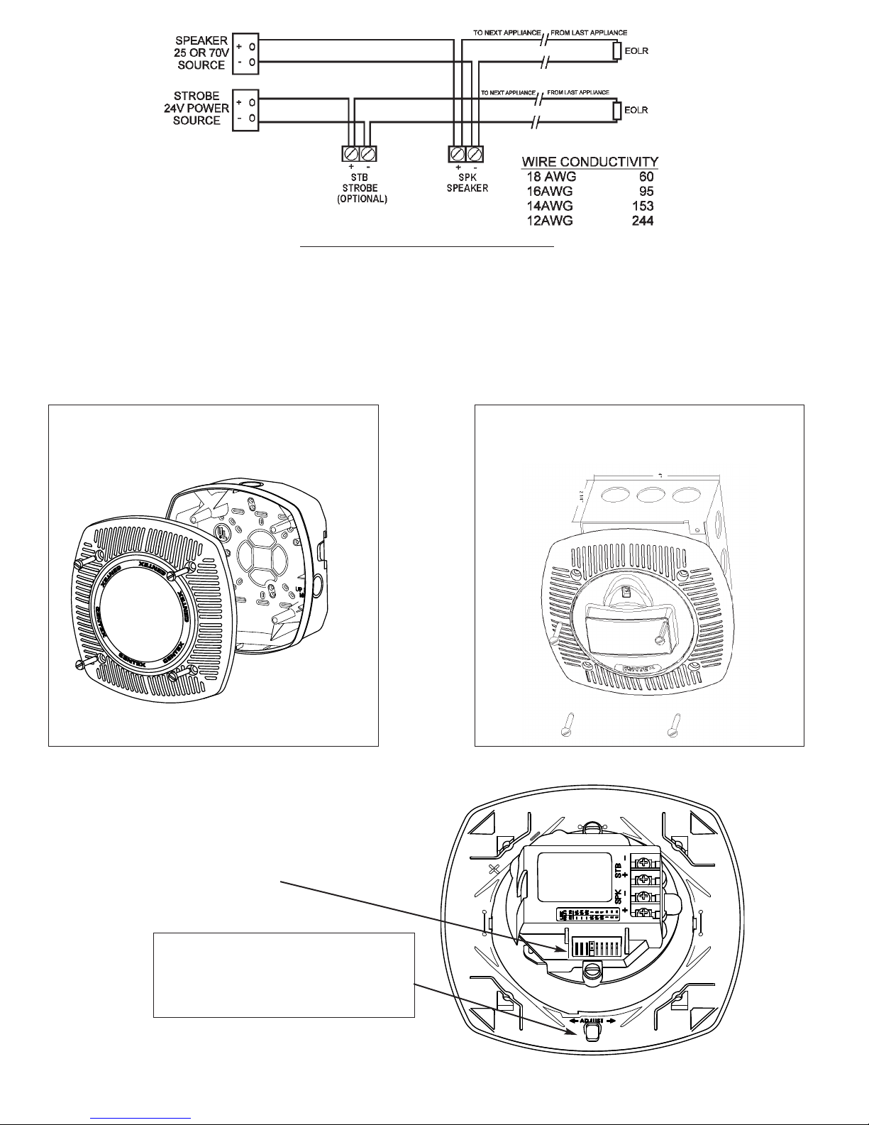
2. Remove mounting screw and slide signal off from bracket.
3. Replace unit that was removed to restore wiring supervision and to eliminate system trouble alert.
4. Carefully pack the defective unit (the manufacturer cannot be responsible for consequential damage due to shipping or mis-handling). Include your return address
and complete details as to the nature of the difficulties being experienced and date of installation.
5. Return to: Gentex Corporation, 10985 Chicago Dr., Zeeland MI 49464. Prior to returning, call the Gentex field service department at 1-800-436-8391 or e-mail
LIMITED WARRANTY
For a period of 36 months from the date of purchase or a maximum of 42 months from the date of manufacture, Gentex warrants to you the original purchaser that your appliance will be free from defects
in workmanship, materials and construction under normal use and service. If a defect in workmanship, materials and construction should cause your appliance to become inoperative within the warranty
period, Gentex will repair your appliance or furnish you with a new or rebuilt appliance without charge to you except for postage required to return the appliance to us. Gentex will not reimburse you for repairs
or replacement parts provided by other parties. Your repaired or replacement appliance will be returned to you free of charge and it will be covered under the warranty for the balance of the warranty period.
The warranty is void if our inspection of your appliance shows that the damage or failure was caused by abuse, misuse, abnormal usage, faulty installation, improper maintenance or repairs other than those
performed by us.
ANY WARRANTIES IMPLIED UNDER ANY STATE LAW INCLUDING IMPLIED WARRANTIES F MERCHANTABILITY R FITNESS F R A PARTICULAR PURP SE APPLY NLY F R THE WAR-
RANTY PERI D SPECIFIED AB VE. PLEASE N TE THAT S ME STATES D N T ALL W LIMITATI N N H W L NG AN IMPLIED WARRANTY LASTS. S THE AB VE LIMITATI N MAY N T
APPLY T Y U. GENTEX WILL N T BE LIABLE F R ANY L SS, DAMAGE, INCIDENTAL R C NSEQUENTIAL DAMAGES F ANY KIND ARISING IN C NNECTI N WITH THE SALE, USE R
REPAIR F THIS APPLIANCE. THE MAXIMUM LIABILITY F GENTEX SHALL N T IN ANY CASE EXCEED THE PURCHASE PRICE PAID BY Y U F R THE APPLIANCE. PLEASE N TE THAT
S ME STATES D N T ALL W THE EXCLUSI N R LIMITATI N F INCIDENTAL R C NSEQUENTIAL DAMAGES, S THE AB VE LIMITATI N R EXCLUSI N MAY N T APPLY T Y U.
If a defect in workmanship, materials or construction should cause your appliance to become inoperable within the warranty period, you must return the appliance to Gentex postage prepaid. You must prove
to the satisfaction of Gentex the date of purchase of your appliance. Warranty service may only be performed by Gentex personnel at Gentex's facilities in Zeeland, ichigan. You must also pack the
appliance to minimize the risk of it being damaged in transit. You must also enclose a return address. Appliances returned for warranty service should be sent to: Gentex Corporation, 10985 Chicago Dr.,
Zeeland I 49464. If we receive an appliance in a damaged condition as the result of shipping, we will notify you and you must seek a claim with the shipper.
THIS WARRANTY GIVES Y U SPECIFIC LEGAL RIGHTS AND Y U MAY ALS HAVE THER RIGHTS WHICH VARY FR M STATE T STATE.
Gentex Corporation
10985 Chicago Drive, Zeeland I 49464
Phone: 800-436-8391
www.gentex.com
550-0490-AAB 09/01/09
Important Notice:
These materials have been prepared by Gentex Corporation ("Gentex") for informational purposes only, are necessarily summary, and are not purported to serve as legal advice and should not be used as such. Gentex makes no representations and warranties, express or implied, that these materials are
complete and accurate, up-to-date, or in compliance with all relevant local, state and federal laws, regulations and rules. The materials do not address all legal considerations as there is inevitable uncertainty regarding interpretation of laws, regulations and rules and the application of such laws, regulations and
rules to particular fact patterns. Each person's activities can differently affect the obligations that exist under applicable laws, regulations or rules. Therefore, these materials should be used only for informational purposes and should not be used as a substitute for seeking professional legal advice. Gentex will
not be responsible for any action or failure to act in reliance upon the information contained in this material.
Page 4
VI. CHECKOU AND ROUBLESHOO ING
1. Supply power to the system control panel. The auxiliary signaling device should not be activated.
2. If the signal is activated:
a. Check all smoke and fire detectors in the system to make sure they have not been activated.
b. Check all wiring connections to make sure the signal detection circuits are not reversed or shorted together. Check wire color codes and traces.
3. To test the SSPKCLP Series and other signaling appliances, trip the auxiliary panel, activate alarm circuit at the main control panel or activate one of the fire
detection units in the system. All auxiliary signals should be activated.
4. An operational test on this product should be conducted in accordance with National Standards or at a minimum annually and more often if dictated by local and state
codes or authorities having jurisdiction.
SIGNALING APPLIANCE LIMI A IONS:
Your speaker meets or exceeds current audibility requirements of Underwriters Laboratories. owever, if the appliance is located outside a bedroom it may not wake
up a sound sleeper, especially if the room door is closed or only partially open.
This manual suits for next models
2
Table of contents
Other Gentex Speakers manuals